Speed Control of Brushless DC Motor Using
Model Reference Adaptive Control
Thasneem.M.S.1, Shalu George K.2
PG Student, Dept. of EEE, Mar Baselios College of Engineering and Technology, Thiruvananthapuram, Kerala, India1 Assistant Professor, Dept. of EEE, Mar Baselios College of Engineering and Technology, Thiruvananthapuram,
Kerala, India 2
ABSTRACT: Brushless DC motor drives are widely used in various industrial systems, such as servomotor drives, medical, automobile and aerospace industry. These are electronically commutated motor and offer many advantages over brushed DC motors which include increased efficiency, longer life, low volume and high torque. The main objective of the thesis is to design a controller to keep the output speed of the BLDC motor constant, under different operating conditions such as parameter variations, load disturbances etc. In model reference adaptive control, the plant output is varied with respect to the output of the reference model with some adjusting mechanism in order to obtain the speed control. The platform for modelling of BLDC motor and simulation of the control is MATLAB/Simulink
KEYWORDS: Brushless DC motors, PID Controller, Model Reference Adaptive Control, Lyapunov Stability Method.
I.INTRODUCTION
BRUSHLESS DC motors have wide industrial applications. These are used generally in servo, actuation, positioning and variablespeed applications where precise motion control is needed. They have been applied in the automotive, HVAC, electronics, computer, semiconductor and medical industries, BLDC motors have long been used in industrial applications such as actuators, feed drives for CNC machines, industrial robots, extruder drives. They are constructed in an inside out configuration with rotor having a set of permanent magnets and a stationary armature winding excited by an electronic commutation controller. The simple construction of BLDC motor has the advantage of high torque, low inertia and wide speed range. These motors exhibit better heat dissipation, improved efficiency, long life and greater power range. Due to lack of commutator and brushes their weight and size is reduced. The disadvantage of BLDC motor is of higher cost which occurs due to the need of complex electronic speed controllers.For BLDC motors, brushes and commutators are absent. The commutation is done electronically by controlling the power switches that are used in the inverters of BLDC motors. Trapezoidal back emf and rectangular stator current are needed to produce a constant electric torque for such type of motors. The commutation region of back emf should be as small as possible so as to make it difficult to commutate a phase of that motor when driven by current source inverter. The flat portion of back emf should be 120o for constant torque production.
controllers using Fuzzy based PID controllers came into existence[5].A single set of Fuzzy rules were used for controlling kp,ki and kd values in the controller. It failed to adapt with change in parameters
In this paper a controller is designed to regulate the speed of BLDC motor using a conventional PID control technique and also a control technique with model reference adaptive control is used. A comparison of both these techniques are done based on the performance parameters like settling time and maximum overshoot.
The outline of this paper is as follows. Section II is the model description of BLDC motor; Section III involves the complete drive system for BLDC motor and Section IV is the design of controller to regulate the speed. The simulation results followed by its analysis is described in Section V Concluding remarks are given in Section VI.
II.SYSTEM MODEL
BLDC motor drive system consisting of BLDC motor and IGBT inverter is designed based on the assumptions that all stator phase windings are having same resistance per phase for stator windings; constant self and mutual inductances; ideal power semiconductor devices; negligible iron losses and motor is unsaturated.
The line to line voltages of BLDC motors in matrix form neglecting mutual inductances is given in (1)
a c c b b a c b a c b a ca bc ab e e e e e e i i i dt d L L L L L L i i i R R R R R R V V V 0 0 0 0 0 0 (1)
where L is the mutual inductance ,R is the stator resistance per phase ,ea ,eb and ec are back EMFs of phases a ,b and c respectively and ia ,ib and ic are the phase currents of phases a,b and c.
The electromagnetic torque developed by the motor is given by
I
k
i
e
i
e
i
e
T
e
a a
b b
c c
t
1
)
(
(2)where
i
a
i
b
i
c
I
,ω is the angular velocity in radians per second and kt is the torque constant.Since this electromagnetic torque is used to overcome the opposing torques of inertia and load,it can be utilized to overcome the inertial and opposing torques of inertia,it can be written as
M M l eB
dt
d
J
T
T
(3)The transfer function model of BLDC motor is given by
e tt
k
k
sRJ
JL
s
k
s
V
s
s
G
2
(4)
Multiplying and dividing throughout the equation by
R
k
k
R
t e
1
.Then Transfer function becomes,
1
1
2
s
s
k
s
V
s
s
G
m e
m e
(5)
Where
t e m
k
k
RJ
is the mechanical time constant and
R
L
e
is the electrical time constant.III.COMPLETE DRIVE SYSTEM
The fig:2 shows the complete block diagram showing the drive system of BLDC motor. Drive system includes the BLDC motor, inverter, controller and three Hall Effect sensors. Reference speed to which the motor is to be regulated is given as input to the controller. The rotor position is detected by using the three Hall Effect sensor signals and is fed back to the controller along with actual speed of BLDC motor. The controller generates the control signal based on the model reference adaptive control law which is used for speed regulation. These control signals are then converted to Pulse Width Modulated signal which are given to drive the inverter switches. The control signal varies the duty cycle of the pulses which are applied across the inverter switches. This controls the average voltage across the winding so that speed of the motor is varied.
IV.CONTROLLER DESIGN
A. PID Controller
It has wide industrial applications as it need only less parameters to be tuned. It eliminates the steady state error by integral action and anticipates the change in output by derivative action. For tuning of parameters in PID controller a lot of techniques are available. Zeigler Nicholas Tuning method is the most popular method for tuning of PID controller. It depends mainly on step response of the system.
The continuous control signal u (t) of the system is given by,
dt
t
de
T
t
e
T
t
e
k
t
u
di p
)
(
)
(
1
)
(
)
(
(4)Using Zeigler Nicholas method of tuning the parameters of the PID controller is given by kp=5.7748 ,ki=1605.29 and kd=0.00468.
Figure 3: Simulink block diagram of PID controller B. Model Reference Adaptive Controller
Adaptive Control process is the one that continuously and automatically measures the dynamic behavior of plant, compares it with desired output and uses the difference to vary adjustable system parameters or to generate the actuating signal in such a way as to obtain optimal performance. An adaptive control system has two loops. One is the normal feedback with process and controller and the other loop consists of the adjustment loop. The parameter adjustment loop is often slower than the normal feedback loop. It can adapt to any change in the speed which occurs due to variation in load or due to external disturbances.
Loss function, 2
2
1
e
J
(5)In order to minimize the function, the control parameters should be changed in negative direction of the function.
e
e
F
t
(6)
e
is called the sensitivity derivative of the system.
A critically damped second order system is chosen as reference model with damping ratio as 1 and natural frequency as 1000 whose transfer function is given by
1000000 2000
1000000 )
( 2
s s
A B s G
m m
m (7)
The control law is chosen as
)
(
)
(
t
Sy
t
Tu
u
c
(8)where
b
b
T
m andb
a
a
S
m
are the controller polynomials andu
c(
t
)
is the desired speed of the motor.The update rule for controller parameter using MIT rule is described by
e a s
by dt
dS
e a s
bu
dt dT
m m c
(9)
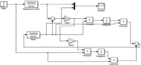
Figure 4: Simulink model of Model Reference Adaptive Controller using MIT rule
ii) MRAC with Lyapunov Stability Method
Let the reference model be given as a first order system
Let the controller be
(11)
Error,e=y-ym
Error goes to zero when parameters,
The Lyapunov Function is taken as
According to Lyapunov, the system is said to be stable when dV/dt is negative definite. So in order to make the system stable the parameters are updated as
Then the derivative dV/dt becomes –ame2 which is negative definite.Hence the system is stable. c
m m m
m
a
y
b
u
dt
dy
)
(
)
(
)
(
t
1u
t
2y
t
u
c
b a a
b b
m m
2 1
) ) (
1 ) (
1 ( 2 1 ) , ,
( 1 2
2 2
2 2
1 m b bm
by a
a b by e e
V
ye dt
d
e u dt
d
c
2 1
(10)
(12)
(13)
(14)
V. RESULT AND DISCUSSION
A Brushless motor drive system was modeled. Adaptive controller with MIT rule and Lyapunov Stability Method was designed and applied to the model and a compared with the results of the conventional PID controller. All the simulations were carried out in MATLAB/ Simulink. Step input was given as the reference to study the response of controller.Fig.5 shows the response of BLDC motor drive system without controller.
A.Response of PID controller
The controller parameters for the conventional PID controller are found such that it guarantees required tracking and also maintains the stability of the overall system. Zeigler Nicholas method of tuning is used to find the controller parameter which cope with the steady state error, overshoot and settling time requirements. The designed controller parameters are kp =5.7748, ki=1605.29, kd=0.00468 for speed tracking performance. The step responses of the PID controller for the system with variation in speed from 1000 rpm to 1500 rpm is shown in Fig. 6 and Fig.7 respectively High overshoot upto 3000 rpm is observed for the system. This can cause harm to the motor. In order to reduce overshoot the controller with Model Reference Adaptive control technique is designed.
Time(s)Fig.7 : Response of PID controller
B. Response of Model Reference Adaptive control
The Model Reference Adaptive controller is designed as discussed in the above sections. Error between the reference speed and actual speed is forced to zero using adaptation mechanism. The responses of the system when MRAC with MIT rule is applied with variation of speed from 1000 rpm to 1500 rpm is shown in fig.9 For Adaptive controller with MIT rule we can see that the disturbances and overshoot are considerably reduced, thus reducing the steady state error and settling time. But have considerable overshoot.
Fig.8: Response of Model Reference Adaptive controller With MIT rule
S
p
e
e
d
(rp
m
)
Time(s)
S
p
e
e
d
(rp
m
Fig.9 Response of Model reference Adaptive controller with Lyapunov Stability method
The model reference adaptive control using Lyapunov stability method shows considerably less overshoot and perfect tracking control with stability is ensured. Thus Model Reference Adaptive Control using Lyapunov Stability Method shows the best control performance as compared to PID controller. Only an overshoot of 6.7 % is observed.
TABLE I
Comparison between the characteristics of two controllers
Performance Characteristics
PID controller
MRAS with
MIT rule
MRAS With Lyapunov Stability Method Maximum
Overshoot
81.2 % 17 % 6.7 %
Settling time 0.05 s 0.8 s 0.2 s
TABLE II
Specifications of BLDC motor used for simulation
PARAMETERS VALUES
Rated Power 6000W
Rated Voltage 315 V
Rated Current 20 A
Rated speed 1500 rpm
Rated Torque 30 Nm
Stator Resistance 0.43Ω
Stator inductance 0.00255H Inertial Constant 0.0011 Viscous Friction
Coefficient
0.05
VI.CONCLUSIONS
The model of BLDC motor is developed and a controller is designed using PID controller and Model Reference Adaptive controller algorithm with MIT rule as well as Lyapunov Stability method such that the speed control is obtained and is implemented using MATLAB/Simulink. A comparative study between these two techniques were
Time(s)
S
p
e
e
d
(rp
m
REFERENCES
[1] Vinod Kr Singh Patel, A.K.Pandey, “Modelling andSimulation of Brushless DC Motor Using PWM ControlTechnique”, International Journal of Engineering Researchand Applications, Vol. 3, Issue 3, May-Jun 2013, pp.612-620., 2005.
[2] Atef Saleh Othman Al-Mashakbeh, “Proportional Integral and Derivative Control of Brushless DC Motor”, European Journal of Scientific Research 26-28 July 2009, vol.35, pg 198-203.
[3] “Modelling and Control of Three Phase BLDC Motor using PID with Genetic Algorithm”, UK Sim 13th International Conference on Modelling and Simulation,pp.189-194,2011.
[4] Anjali.A.R “Control Of Three Phase BLDC Motor Using Fuzzy Logic Controller” International Journal of Engineering Research &Technology (IJERT), Vol. 2, Issue 7, July 2013
[5] R. Kandiban, R. Arulmozhiyal “Design of Adaptive Fuzzy PID Controller for Speed control of BLDC Motor” International Journal of Soft Computing and Engineering ,Volume-2, Issue-1, March 2012
[6] Design and Implementation of Adaptive Fuzzy Controller for Speed Control of Brushless DC Motors N.Senthil Kumar, C.Senthil Kumar 2010 International Journal of Computer Applications (0975 - 8887)Volume 1 – No. 27.
[7] Atef Saleh Othman Al-Mashakbeh, “Proportional Integral andDerivative Control of Brushless DC Motor”, EuropeanJournal of Scient i fic Research 26-28 July 2009, vol.35, pg 198-203.
[8] Ms. Juli Singh, “Analysis the speed control of BLDC motordrive using sensors” International Journal of EngineeringResearch and Applications, Vol. 2, Issue 3, May-Jun 2012,pp.2868-2884
[9] S. Anbu, N. Jaya,” Design of Adaptive Controller Based On LyapunovStability for a CSTR” International Journal of Electrical, Computer, Energetic, Electronic and Communication Engineering Vol:8, No:1, 2014,pp.176-179.