Simulation of Master-Slave Topology
Implemented Using CAN Protocol
Thejus Mathew1, Dr. Dinesh M. N2, Mariappan.B3
PG Student [Power Electronics], Dept. of EEE, R.V College of Engineering, Bengaluru, Karnataka India1 Associate Professor, Dept. of EEE, R.V College of Engineering, Bengaluru, Karnataka, India2
R & D Specialist, ABB India Ltd, Bengaluru, Karnataka, India3
ABSTRACT: CAN (Controller Area Network) protocol is a communication protocol which is widely used in
automobile industry.It is used to establish communication when two or moreembedded systems are operated at a time. In this paper algorithm for implementing master-slave topology using CAN protocol is discussed. There is no restriction in the number of units that can be connected through CAN protocol. In master-slave topology one unit will be master and remaining will be slave. In this configuration master to slave communication is possible. Algorithm for master-slave topology using CAN protocol is verified by using Simulink.
KEYWORDS:CAN(Controller Area Network), International Standard Organisation, Open Systems Interconnections
I.INTRODUCTION
CAN (Controller Area Network) protocol is widely used in automobile industry. CAN protocol was first introduced by Robert Bosch. Purpose of introduction of CAN protocol was to increase reliability and efficiency of automobile system. It is a serial communication protocol. The units which are connected through CAN protocol can be transmit and receive data. It efficiently supports real time control with high level of security. Thedata are transmitted using specific CAN message format. Each message has identifier bits which give specific identity over other messages.
In this paper, it proposes an algorithm for master-slave topology for units which are connected through CAN protocol. Master-slave topology is commonly used model for communication protocols. In this configuration one device (known as the master) which controls one or more other devices (known as slaves). Each unit will have assigned to id numbers. The algorithm made units to operate in master or slavebased on this id number. Each unit will transmit their own id and receive other unit id through the CAN communication channel. The algorithm compares id of each device with other device id. The algorithm enables device as master whose id has less value compared to other device id. The remaining devices as slaves. Once this topology is established, then acontinuous transmission of data from master to slave take place.
II.THE CAN PROTOCOL OVERVIEW
The CAN protocol find main applications in automobile industry. It is used to exchange real time information between various electronic units in an automobile. Automobile consists of various electronic units such as engine control, active suspension, brake control, air conditioning etc. CAN communication enables information exchange between these devices for proper functioning.
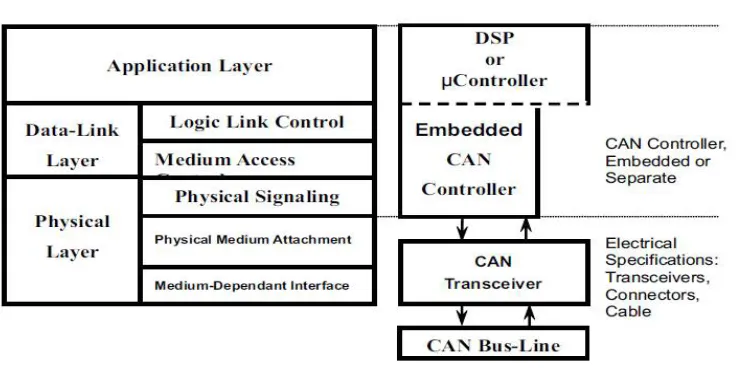
Fig 1 The Layered ISO 11898 Standard Architecture.
The Application layer mainly for implementing software for CAN communication. DSP or microcontroller is used for this purpose. The software is written for controlling CAN controller and also it addresses, registers in DSP or microcontroller for data transmission and reception.
The Data link layer consists of CAN controller, which transmits and receives information, set timings for data transmission and reception, ensuring error free messages. CAN controller can be embedded with DSP or microcontroller or separate.
The Physical layer is the basic hardware for CAN network. It converts CAN message 1’s and 0’s into electric pulses leaving during transmission and electric pulses into CAN message during the reception. The physical layer generally consists of transceivers, connectors, cables.
ISO 11898 specifies two versions of CAN, Standard CAN and Extended CAN with 11-bit and 29-bit identifier respectively. The bit fields of Standard and Extended CAN is shown in the Fig 2 and Fig 3 respectively.
Fig 2 Standard CAN: 11- bit identifier
Fig 3 Extended CAN- 29-bit identifier
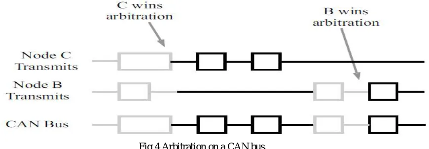
In CAN communication any of the node start to transmit message. If 2 or more nodes start transmitting message will lead to collision of the message. In order to avoid collision,arbitration takes place between messages. If two units are ready for transmission, then unit with more no of dominant bits in identifier bits wins over other unit and continues transmission. The arbitration process is shown in the Fig 4. The entire arbitration process is carried out by CAN controller.
Fig 4 Arbitration on a CAN bus.
III.ALGORITHM FOR MASTER-SLAVE TOPOLOGY
Each node will be assigned with idvalue. Variable ‘Realtimemode’ is defined which represents whether particular node is master or slave. If ‘Realtimemode’ is master, then node can transmit and receive data. If ‘Realtimemode’ is slave, then node can receive only data. Once CAN network is established, ‘Realtimemode’ of every node is master. It begins to transmit its id and receives another node’s id. Each node compares its id with other id’s. If its id has less value compared to any of the received id’s, then ‘Realtimemode’ of that node remains as master. Similarly, if any of the node’s id is greater than any of the received id’s then ‘Realtimemode’ of that node changed to a slave. Once node becomes master, then it continues transmitting data. Fig 5 shows flow chart for algorithm.
IV.SIMULATION
Verification of algorithm is done by performing simulation in SIMULINK package available in MATLAB2013B.In Simulink, Vehicle Network Toolbox is available.It is provided with various blocks which supports CAN communication. Three nodes are connected through CAN communication. The CAN Configuration block is used for establishing virtual channel for communication. In this block there is provision of providing baud rate. Inside each node CAN Pack, CAN Transmit, CAN Receive, CAN Unpack blocks are used.
CAN Pack: It is used to pack messages which are ready for transmission. It is used to load signal data into message at specified intervals during simulation. It provides provision for entering an identifier value. This identifier value will be the node.id. User can specify thelength of bytes, the data type of message which is to be transmitted.
CAN Transmit: It transmits messages into CAN network.
CAN Receive: This block can receive messages from CAN network. It can filter incoming messages according to their identifier value.
CAN Unpack: This block unpacks CAN messages into signals. It can provide output such as identifier, remote, error, timestamp, length, status.
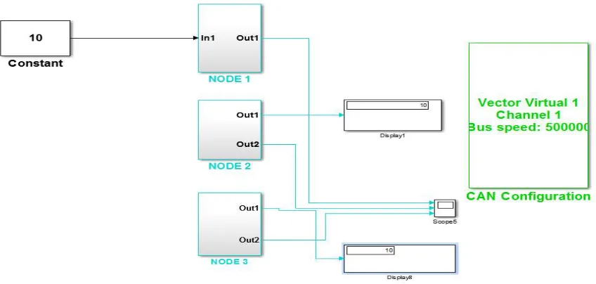
Implementation of Master-salve topology using CAN protocol in Simulink is shown in Fig 6
Fig 6 Implementation of Master-slave topology using CAN protocol in Simulink.
V. RESULTS AND DISCUSSION
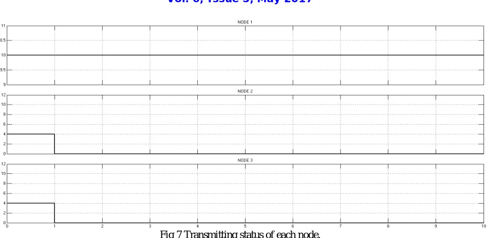
Fig 7 Transmitting status of each node.
In Fig 7 shows during time interval 0 to 1sec every node is master, it transmits data which contain node.id. After 1sec, node1 is master and remaining become slave. Node 1 continue transmitting and slave nodes stop transmission.
VI.CONCLUSION
Implementation of Master slave topology is done by using CAN protocol. Algorithm makes node with least id value as master and remaining as slaves. Algorithm is verified by performing simulation in Simulink.
REFERENCES