Scholarship@Western
Scholarship@Western
Electronic Thesis and Dissertation Repository
8-19-2014 12:00 AM
Experimental Study of Two-Phase Flow in a Liquid Cross-Flow and
Experimental Study of Two-Phase Flow in a Liquid Cross-Flow and
an Effervescent Atomizer
an Effervescent Atomizer
Mona Hassanzadeh Jobehdar
The University of Western Ontario
Supervisor
Dr. Kamran Siddiqui
The University of Western Ontario
Graduate Program in Mechanical and Materials Engineering
A thesis submitted in partial fulfillment of the requirements for the degree in Doctor of Philosophy
© Mona Hassanzadeh Jobehdar 2014
Follow this and additional works at: https://ir.lib.uwo.ca/etd
Part of the Mechanical Engineering Commons
Recommended Citation Recommended Citation
Hassanzadeh Jobehdar, Mona, "Experimental Study of Two-Phase Flow in a Liquid Cross-Flow and an Effervescent Atomizer" (2014). Electronic Thesis and Dissertation Repository. 2273.
https://ir.lib.uwo.ca/etd/2273
This Dissertation/Thesis is brought to you for free and open access by Scholarship@Western. It has been accepted for inclusion in Electronic Thesis and Dissertation Repository by an authorized administrator of
(Thesis format: Integrated-Article)
by
Mona Hassanzadeh Jobehdar
Graduate Program in Engineering Science Department of Mechanical and Materials Engineering
A thesis submitted in partial fulfillment of the requirements for the degree of
Doctor of Philosophy
The School of Graduate and Postdoctoral Studies The University of Western Ontario
London, Ontario, Canada
ii
Abstract
Effervescent atomization uses the internal gas-liquid mixture to produce spray. The behavior
of two-phase flow inside the atomizer influences the spray characteristics and is dependent
on the atomizer internal geometry and operating conditions. The present study is conducted
in two parts; study of the bubble formation from a novel submerged nozzle in a liquid
cross-flow and investigation of the internal and external two-phase cross-flows in an effervescent
atomizer.
The present study investigated the performance of a novel nozzle developed by Gadallah and
Siddiqui (2013) in the liquid cross-flow. The impact of the nozzle shape, its configurations
and orientations was experimentally investigated. The results showed that the novel nozzle
generates smaller bubbles at higher detachment frequency for all cases compared to the
standard nozzle. It is found that the rebound of the bubble from a side hole plays a key role in
the early bubble detachment.
For the effervescent atomizer study, the influence of various operating and geometric
parameters of the atomizer on the internal flow and spray droplet characteristics were studied
along with a design improvement to the atomizer internal geometry. The results
demonstrated that a conical base aerator tube and shorter mixing zone length provide more
uniform bubbles in smaller size. A new type of bubble breaker was designed and tested in an
effervescent atomizer. The results show that both internal and external two-phase flows in the
atomizer were strongly influenced by bubble breaker configurations (diameter and number of
holes). It was found that the liquid shear stress is the dominant force causing the bubble
elongation and its eventual breakup.
Keywords
Two-Phase flow; Novel nozzle; Effervescent atomizer; Liquid cross-flow; Bubbly flow;
iii
Co-Authorship Statement
I hereby declare co-authorship in the chapters listed below:
Chapter 2:
Bubble formation process from a novel nozzle design in a liquid cross-flow
Authors: M. Hassanzadeh, K. Siddiqui, A. H. Gadallah, W. Chishty
Status: It has been submitted to International Journal of Multiphase Flow.
Experimental work and data analysis were performed by M. Hassanzadeh. A. H. Gadallah
provided some consultation on the experimental design. The manuscript was written by M.
Hassanzadeh and reviewed by K. Siddiqui, A. H. Gadallah and W. Chishty.
Chapter 3:
Investigation of two-phase flow in an effervescent atomizer
Authors: M. Hassanzadeh, K. Siddiqui, A. H. Gadallah, W. Chishty
Status: It will be submitted for publication.
Experimental work and data analysis were performed by M. Hassanzadeh. A. H. Gadallah
provided some consultation on the experimental design. The manuscript was written by M.
Hassanzadeh and reviewed by K. Siddiqui, A. H. Gadallah and W. Chishty.
Chapter 4:
Effect of bubble breaker on the effervescent atomization process
Authors: M. Hassanzadeh, K. Siddiqui, A. H. Gadallah, W. Chishty
Status: It will be submitted for publication.
Experimental work and data analysis were performed by M. Hassanzadeh. A. H. Gadallah
provided some consultation on the experimental design. The manuscript was written by M.
iv
Preface
“Research is to see what everybody else has seen and to think what nobody else has thought”
Albert Szent-Gyorgyi
v
Acknowledgments
First and foremost, I would like to gratefully and sincerely thank my supervisor, Dr. Kamran
Siddiqui for his inspiration, incomparable assistance and invaluable guidance. Without his
guidance and persistence help this dissertation would not have been possible.
I would like to thank the National Research Council Canada (NRC), Natural Sciences and
Engineering Research Council of Canada (NSERC) and the University of the Western
Ontario for the financial support. I would like to acknowledge the faculty and staff of
Mechanical and Materials Engineering Department for their education and support. I would
also like to thank all of my colleagues and friends for their assistance and encouragement.
I would like to express my sincere thanks to Dr. Alireza Daemi for his support during the
past several years and helping me to develop my background in Fluid Mechanics.
My special thanks to my husband for his patience, encouragement and endless love. He was
always there cheering me up and stood by me through the good times and bad.
Finally, the greatest thanks of all must go to my wonderful parents for their unconditional
love and moral support. Words cannot express my gratitude for everything they have done
for me. Although my time in Canada was not easy for them, they always supported me in my
dreams and goals. I owe them everything in my life and I appreciate and love them more than
vi
Table of Contents
Abstract ... ii
Co-Authorship Statement ... iii
Acknowledgments ... v
Table of Contents ... vi
List of Tables ... ix
List of Figures ... x
List of Appendices ... xviii
List of Abbreviations, Symbols, Nomenclature ... xix
Chapter 1 ... 1
1 Atomizers ... 1
1.1 Introduction ... 1
1.1.1Effervescent atomizer ... 2
1.1.2Bubble formation in a liquid cross-flow ... 7
1.2 Motivation ... 11
1.3 Objective ... 12
1.4 Experimental measurement techniques ... 14
1.4.1Bubble characteristics computation ... 15
1.4.2Droplet characteristics computation ... 16
1.5 Thesis layout ... 19
1.6 References ... 20
Chapter 2 ... 28
2 Bubble formation process from a novel nozzle design in a liquid cross-flow ... 28
vii
2.2 Experimental setup ... 31
2.3 Results and Discussion... 36
2.3.1Bubble detachment mechanism ... 47
2.3.2Glass nozzle ... 51
2.3.3Four side-holes configuration ... 61
2.4 Conclusion ... 66
2.5 References ... 68
Chapter 3 ... 71
3 Investigation of two-phase flow in an effervescent atomizer ... 71
3.1 Introduction ... 71
3.2 Experimental setup and techniques ... 76
3.2.1Effervescent atomizer ... 76
3.2.2Aerator tubes ... 77
3.2.3Experimental setup ... 79
3.2.4Visualization and measurement technique ... 79
3.3 Results and Discussion... 83
3.3.1Internal flow ... 83
3.3.2External flow (Spray) ... 101
3.4 Conclusion ... 113
3.5 References ... 115
Chapter 4 ... 120
4 Effect of bubble breaker on the effervescent atomization process ... 120
4.1 Introduction ... 120
4.2 Experimental setup and techniques ... 124
4.2.1Effervescent atomizer ... 124
viii
4.2.3Bubble breakers ... 127
4.2.4Experimental setup ... 128
4.2.5Visualization and measurement technique ... 130
4.3 Results and Discussion... 131
4.3.1Effect of bubble breaker single-hole diameter ... 133
4.3.2Effect of number of holes in the bubble breaker ... 149
4.4 Conclusion ... 164
4.5 References ... 166
5 Conclusions and Recommendations ... 170
5.1 Overall Conclusions ... 170
5.2 Recommendations for future work ... 174
5.3 Contributions ... 175
Appendices ... 176
Appendix A... 176
Appendix B... 177
ix
List of Tables
x
List of Figures
Figure 1-1: Schematic of an effervescent atomizer and atomization process. ... 5
Figure 1-2: Three different flow regimes inside the effervescent atomizer (a) bubbly
flow, (b) slug flow, (c) annular flow. ... 6
Figure 1-3: Different flow regimes caused by injection of gas into a liquid stream. (a)
Individual bubbly flow (b) Bubbly flow with bubble-bubble interaction (c) Jet flow. ... 9
Figure 1-4: Governing force acting on the bubble (a) During formation, (b) After
detachment... 11
Figure 1-5: Image processing of the bubble formation to measure bubbles
characteristics (a) original image (b) image after adjustment and converting into the
binary image (c) image after inverting and dilation (d)image after filling the holes and
erosion(e) image after removing the noise (f) image after selecting the only detached
bubble. ... 17
Figure 1-6: Image processing of spray droplets to measure droplet characteristics (a)
original image (b) image after adjustment and converting into the binary image (c)
image after inverting (d) image after erosion, dilation and filling the holes and
erosion(e) image after removing the noise (f) image after selecting the only detached
droplets... 18
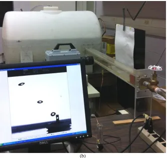
Figure 2-1: Experimental setup; (a) Schematic and (b) photograph. ... 34
Figure 2-2: Nozzle designs and orientations with respect to the flow direction used in
the experiments. (a) Standard nozzle, (b) Novel nozzle, 2 side-holes in-line orientation,
(c) Novel nozzle, 2 side-holes perpendicular orientation. hs=1.6mm. ... 35
Figure 2-3: Governing force acting on the bubble (a) During formation, (b) After
xi
B L
the standard nozzle at three different gas flow rates. Error bars (based on the standard
error of the mean) are smaller than the size of the symbols. ... 38
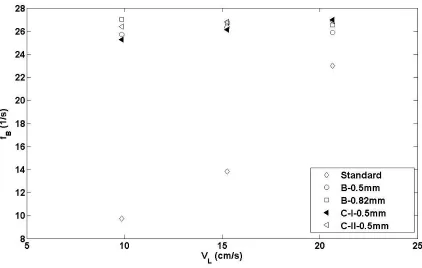
Figure 2-5: Bubble detachment frequency (fB) versus average liquid velocity (VL) at gas
velocity of 31.84 (cm/s). Error bars (based on the standard error of the mean) are
smaller than the size of the symbols. ... 40
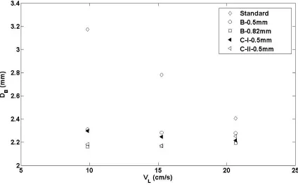
Figure 2-6: Bubble diameter (DB) versus average liquid velocity (VL) at a gas flow rate
of 31.84 (cm/s). Error bars (based on the standard error of the mean) are smaller than
the size of the symbols... 42
Figure 2-7: Bubble detachment frequency (fB) versus average gas velocity (Vg) at a
liquid velocity of 9.85 (cm/s). Error bars (based on the standard error of the mean) are
smaller than the size of the symbols. ... 43
Figure 2-8: Bubble diameter (DB) versus gas velocity (Vg) at a liquid velocity of 9.85
(cm/s). Error bars (based on the standard error of the mean) are smaller than the size
of the symbols. ... 44
Figure 2-9: Strouhal number (St) versus GLR. Error bars (based on the standard error
of the mean) are smaller than the size of the symbols. ... 45
Figure 2-10: Mean bubble diameter to inner nozzle diameter ratio (DB/DN) versus gas to
liquid flow rate ratio (GLR). Error bars are (based on standard error of the mean)
smaller than the size of bullets. ... 46
Figure 2-11: Image sequences showing the effect of liquid cross-flow on the dynamic
gas-liquid interface motion during bubble formation from the novel nozzle with
side-hole diameter of 0.7 mm at a gas flow rate of 0.28 cm3/s. (a) Standard nozzle at liquid
flow rate of 255 cm3/s (Δt=4ms). (b), (c) Novel nozzle in-line and perpendicular
orientation at stagnant liquid flow (Δt=1ms). (d), (e) Novel nozzle in-line and
xii
diameters of in-line novel nozzle at a gas flow rate of 0.168 cm3/s and liquid velocity of
9.85 cm/s (a) novel nozzle with side-hole of 0.5 mm (∆t =5 ms), (b) novel nozzle with
side-hole of 0.7 mm (∆t =4 ms) and (c) novel nozzle with side-hole of 0.82 mm (∆t =4
ms). The liquid stream is from right to left. ... 50
Figure 2-13: Sequence of bubble formation from the standard nozzle at gas flow rate of
826 cm3/s, liquid flow rate of 395 cm3/s, ∆t=1.1ms. ... 52
Figure 2-14: Sequence of bubble formation from the novel nozzle at a gas flow rate of
826 cm3/s and liquid flow rate of 395 cm3/s, ∆t=0.8 ms. ... 55
Figure 2-15: Different stages of the bubble formation and detachment at liquid flow
rates of 255 cm3/s, 395 cm3/s and 535 cm3/s. t=0 is considered for the previous bubble
detachment. (a) Expansion stage (b) Collapse stage (c) Pinch-off. ... 57
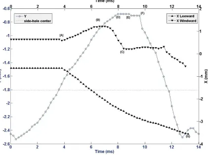
Figure 2-16: Reference coordinate system. ... 58
Figure 2-17: Evolution of gas volume in X and Y direction during the bubble formation
process from two side-holes at a gas flow rate of 826 cm3/s and liquid flow rate of 255
cm3/s. ... 59
Figure 2-18: Evolution of gas volume in X and Y direction during the bubble formation
process from two side-holes at a gas flow rate of 826 cm3/s and liquid flow rate of 535
cm3/s. ... 60
Figure 2-19: Four side-holes nozzle configurations used in the study. (a) Regular four
side-holes, Configuration B. (b) Four side-holes with different distance between holes,
Configuration C. hs=1.6mm, hu=0.8 mm, hs=2.1mm. ... 62
Figure 2-20: Bubble detachment frequency (fB) versus average liquid velocity (VL) at a
gas flow rate of 0.168 (cm3/s). Error bars (based on the standard error of the mean) are
xiii
B L
of 0.168 (cm3/s). Error bars (based on the standard error of the mean) are smaller than
the size of the symbols... 64
Figure 2-22: Strouhal number (St) versus GLR. Error bars (based on the standard
error of the mean) are smaller than the size of the symbols. ... 65
Figure 2-23: Mean bubble diameter to inner nozzle diameter ratio (DB/DN) versus GLR.
Error bars (based on the standard error of the mean) are smaller than the size of the
symbols. ... 66
Figure 3-1: Schematic of the effervescent atomizer used in the study (not to scale). ... 77
Figure 3-2: Schematic of the aerator tubes configurations used in the study, (a) with 4
mm distance between holes (b) 8 mm distance between holes. Aerator tube of identical
hole configuration with (c) conical base and (d) flat base. ... 78
Figure 3-3: (a) Schematic and (b) Photograph of the experimental setup using two
cameras. (c) Photograph of the experimental setup using one camera. ... 82
Figure 3-4: Image sequences showing the bubble formation from AR-4 at a GLR of 0.53
( t=0.45ms). (a) Side view (b) Plan view. ... 85
Figure 3-5: Effect of distance between holes at three different GLRs, ... 87
Figure 3-6: Image sequences showing the transition from aeration zone to the mixing
zone. (a) GLR=0.53, ∆t=22.2 ms), (b) GLR=0.79, ∆t=20 ms), (c) GLR=3.17, (∆t=16.5
ms), (d) GLR=9.55, (∆t=5 ms). ... 91
Figure 3-7: Effect of different GLRs on the two-phase flow behavior inside the mixing
zone. The mixing zone length is 52 mm. The aerator tube is the standard tube. (a) The
images of internal two-phase flow at different GLRs (b) Probability Density Functions
of the bubble diameter (DB). (c) Mean bubble diameter versus GLR. Error bars (based
xiv
atomizer at different GLRs. The length of the mixing zone is 52 mm. ... 96
Figure 3-9: Effect of the aerator tube with and without cone on the bubble size. (a), (b)
Probability Density Function (PDF) of the bubble diameter (DB) at GLR=0.53 and
GLR=3.17, respectively. (c) Mean bubble diameter versus GLR. Error bars (based on
the standard error of the mean) are smaller than the size of the symbols. ... 99
Figure 3-10: Effect of mixing zone length on the flow behavior in the mixing zone at
different GLRs. (a) GLR=0.53, (b) GLR=3.17, (c) GLR=9.55. ... 100
Figure 3-11: Effect of different mixing zone lengths on the bubble size (a), (b)
Probability Density Function (PDF) of the bubble diameter (DB) at GLR=0.53 and
GLR=3.17, respectively. (c) Mean bubble diameter versus GLR. Error bars are smaller
than the size of bullets... 103
Figure 3-12: Probability Density Function (PDF) of (a) the droplet diameter (Dp) and
(b) droplet velocity (Vp) at different GLRs. The mixing zone length is 52mm. ... 106
Figure 3-13: Effect of the aerator tube with and without cone on the droplet diameter
(Dp) in form of (a) Probability Density Function (PDF) at GLR=0.53. (b) Mean droplet
diameter versus GLR. The mixing zone length is 52mm. Error bars (based on the
standard error of the mean) are smaller than the size of the symbols. ... 107
Figure 3-14: Effect of the aerator tube with and without cone on the droplet velocity in
the form of (a) Probability Density Function (PDF) at GLR=0.53. (b) Normalized
droplet velocity (Vp/VLa) versus GLR. The mixing zone length is 52mm. Error bars
(based on the standard error of the mean) are smaller than the size of the symbols. .. 108
Figure 3-15: Effect of the different mixing zone length on the droplet diameter in the
form of (a) Probability Density Function (PDF) at GLR=0.53 (b) Mean droplet
diameter versus GLR. The aerator tube has the conical base. Error bars (based on the
xv
form of (a) Probability Density Function (PDF) at GLR=0.53, (b) Normalized droplet
velocity (Vp/VLa) versus GLR. The aerator tube has the conical base. Error bars (based
on the standard error of the mean) are smaller than the size of the symbols. ... 112
Figure 4-1: Schematic of the effervescent atomizer used in the study (not to scale). ... 126
Figure 4-2: Schematic of the bubble breaker used in the study (a) Single-hole bubble
breakers, (b) Multi-hole bubble breakers. ... 127
Figure 4-3: (a) Schematic and (b) photograph of the experimental setup to investigate
the internal two-phase flow. (c) Photograph of the experimental setup to investigate the
external two-phase flow (spray droplets). ... 129
Figure 4-4: Effect of bubble breaker on the flow behavior in the mixing zone upstream
the exit orifice at different GLRs (a) GLR=0.53, (b) GLR=3.17, (c) GLR=9.55. In each
image pair, left image presents the case with breaker and right image presents the case
without breaker. ... 133
Figure 4-5: Effect of bubble breaker hole diameter at different GLRs (a) GLR=0.53, (b)
GLR=3.17, (c) GLR=9.55. ... 135
Figure 4-6: Image sequences showing the mechanism of bubble breakup in single-hole
bubble breaker. (a) First type of bubble fragmentation at the entrance, GLR=0.53,
∆t=0.75 ms, (medium hole). (b) Second type of small-size bubble fragmentation inside the bubble breaker, GLR=0.53, ∆t=0.2 ms (large hole) (c) Double breakup, GLR=0.53, ∆t=0.25ms (medium hole). ... 139
Figure 4-7: Effect of bubbles breakers with different single-hole diameters on the
bubble size. Probability Density Function (PDF) of the bubble diameter (DB)at (a)
GLR=0.53, (b) GLR=3.17 and (c) GLR=9.55. (d) Mean bubble diameter (DB) inside the
bubble breakers versus GLR. Error bars (based on the standard error of the mean) are
xvi
droplet size. Probability Density Function (PDF) of the droplet diameter (Dp), at (a)
GLR=0.53, (b) GLR=3.17 and (c) GLR=9.55. (d) Mean droplet diameter versus GLR.
Error bars (based on the standard error of the mean) are smaller than the size of the
symbols. ... 146
Figure 4-9: Effect of bubbles breakers with different single-hole diameters on the
droplet velocity. Probability Density Function (PDF) of the droplet velocity (Vp), at (a)
GLR=0.53, (b) GLR=3.17 and (c) GLR=9.55. (d) Normalized mean droplet velocity
(Vp/VLa) versus GLR. Error bars (based on the standard error of the mean) are smaller
than the size of the symbols. ... 149
Figure 4-10: Effect of number of holes in the bubble breakers at different GLRs, (a)
GLR=0.53, (b) GLR=3.17, (c) GLR=9.55. ... 152
Figure 4-11: Bubble breakup mechanism in the multi-hole bubble breakers. (a)
Penetration and fragmentation of a bubble into two holes for the three-hole bubble
breaker (b) Penetration and breakup of bubbles either from one hole or number of
holes in the five-hole bubble breaker. (c) Bubble fragmentation inside the bottom
convergent section. GLR=0.53. ... 155
Figure 4-12: Effect of bubbles breakers with different numbers of hole on the bubble
size inside the holes. Probability Density Function (PDF) of the bubble diameter (DB) at
(a) GLR=0.53, (b) GLR=3.17 and (c) GLR=9.55. (d) Mean bubble diameter (DB) inside
the bubble breaker versus GLR. Error bars (based on the standard error of the mean)
are smaller than the size of the symbols... 158
Figure 4-13: Effect of number of bubble breaker holes on the spray droplet size.
Probability Density Function (PDF) of the droplet diameter (Dp) at (a) GLR=0.53, (b)
GLR=3.17 and (b) GLR=9.55, (d) Mean droplet diameter versus GLR. Error bars
(based on the standard error of the mean) are smaller than the size of the symbols. .. 161
Figure 4-14: Effect of number of bubble breaker hole on the spray droplet velocity.
Probability Density Function (PDF) of droplet velocity (Vp) at (a) GLR=0.53, (b)
xvii
xviii
List of Appendices
Appendix A: Effervescent atomizer ... 176
xix
List of Abbreviations, Symbols, Nomenclature
Abbreviations
GLR Gas to Liquid flow rate ratio
SMD Sauter Mean Diameter
PDF Probability Density Function
Nomenclature
fB Bubble detachment frequency
DB Bubble diameter, mm
DN Inner nozzle diameter, mm
Qg Gas flow rate, cm3/s
QL Liquid flow rate, cm3/s
Vg Gas velocity, cm/s
VL Liquid velocity in the channel, cm/s
St Strouhal number
Fs Surface tension force, dyn
FB Buoyancy force, dyn
FM Gas momentum flux force, dyn
Fp Pressure force, dyn
xx L
FD Drag force, dyn
t Time, ms
∆t Time interval, ms
Dp Droplet diameter, mm
Vp Liquid velocity, m/s
VLa Liquid velocity in the atomizer, m/s
Chapter 1
1
Atomizers
1.1 Introduction
Atomization of liquid into the spray is crucial in wide range of industrial processes such
as; coating [1], spray drying, pharmaceutical [2, 3], chemical reactors [4, 5] and
combustion [6]. There are different types of atomizers. Based on the required energy to
form spray, the common atomizer types are categorized into pressure atomizer, rotary
atomizer, electrostatic, ultrasonic atomizer or twin-fluid atomizer [7]. In an industrial
application, the desired droplet size, the spray shape and the properties of the liquid are
the key parameters to choose a specific type of atomizer [7].
In a pressure atomizer, the pressurized liquid is discharged from an orifice at high
velocity. Due to the requirement of pressurized liquid, the pressure atomizers typically
use low-viscosity liquids. This type of atomization has some limitations such as; large
droplet size and low liquid flow rate [6]. In a rotary atomizer, a rotating surface is located
in front of the liquid jet and the liquid spreads out and forms droplets due to the
centrifugal force. In this type of atomizer, the external mechanical energy is required to
rotate the surface. The electrostatic atomizers and ultrasonic atomizers utilize electrical
and acoustic energies to produce spray. In ultrasonic atomizers, the ultrasound
transducers are used to produce a resonance acoustic wave, which results in
disintegration of the liquid jet and formation of the spray. In electrostatic atomizers, the
liquid accelerated by an electrical charge results in a tiny liquid jet which further breaks
into small-size droplet in small quantities [6, 7]. In twin-fluid atomizer, the kinetic energy
of the pressurized gas used to interact with the liquid results in the liquid phase break up
and formation of the spray. Twin-fluid atomizers usually use air as the driving fluid to
produce spray. They are divided into air-blast, air-assist and effervescent atomizers. This
mixing; external mixing and internal mixing [6, 7, 8]. In air-blast and air-assist atomizers,
air at very high velocity is introduced into already established jet or sheet of liquid before
the exit orifice [6]. A basic limitation of these atomizers is the "low bubble growth rate",
i.e. although the gas is the dissolved phase into the liquid, to enhance the spray quality, it
is necessary for the gas phase to emerge from the liquid jet. To avoid this limitation,
Lefebvre et al. [6, 9] designed an effervescent atomizer in which gas does not impart
kinetic energy to the flowing liquid. In an effervescent atomizer, the low-velocity gas is
injected into the liquid flow, upstream of the exit orifice and this injected gas in the form
of bubbles inside the liquid provides a good atomization.
1.1.1
Effervescent atomizer
Among all conventional atomization techniques, effervescent atomization is known as a
twin-fluid atomization. Effervescent atomization or "aerated-liquid atomization" was
designed and developed by Lefebvre and his colleagues in 1980s and categorized into the
internal two-phase flow mixing [9-12]. Compared to other forms of twin-fluid atomizer,
effervescent atomizer uses low velocity gas injection into the liquid to form bubbly flow
in the liquid stream. The gas-liquid mixture then moves downstream towards the exit
orifice. The presence of bubbles inside the liquid flow enhances the atomization process
by decreasing the fraction of the liquid passing through the exit orifice and by the
expansion of the bubbles inside the liquid after ejection from the orifice. This expansion
of bubbles forms thin ligaments and small droplets due to a sudden pressure drop [8].
There are several advantages for the effervescent atomizers over common atomizers.
These include, excellent atomization at very low gas pressures, significantly smaller gas
flow rates compared to those injected in the most forms of twin-fluid atomizers, and
smaller drop sizes for any given injection pressure [6, 9, 11, 12]. The exit orifice
diameters of the effervescent atomizers are larger in comparison with other types of
atomizers at a similar flow rate [6, 10, 13-15]. The larger exit orifice mitigates the
problems of clogging and hence, the atomization of impure liquids becomes possible [16,
17, 18]. Furthermore, for combustion applications, the air inside the liquid fuel enhances
effervescent atomizer provides reliability and simplicity which results in easy
maintenance and low cost [6].
Like other forms of twin-fluid atomizers, the effervescent atomizer also requires a source
of pressurized gas, which is considered as its main drawback. However, this necessity can
often be satisfied easily, since the effervescent atomization requires low gas pressure and
low gas flow rate [8, 6]. Each effervescent atomizer, in terms of the gas injection
configuration, is either "outside-in" or "inside-out". In the "outside-in" configuration,
liquid stream flows inside a tube while gas is injected from the outside (i.e. peripheral
region) into the liquid. Hence, the liquid flows in a large area due to the configuration of
the gas injection [19]. This configuration has been well investigated previously [13, 18,
20-33]. The other gas configuration is "inside-out", in which gas is injected from aerator
tube in the middle of the atomizer through the aeration holes into the liquid stream
flowing in the peripheral region. While the "outside-in" configuration has a limitation of
geometry change, the "inside-out" configuration is more flexible to geometry variation
and allows changes in the dimensions of the atomizer components [34]. This
configuration has also been studied by some researchers [12, 19, 34, 35, 36].
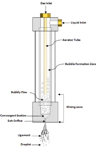
An inside-out effervescent atomizer is composed of gas and liquid inlets, mixing
chamber, aerator tube and the exit orifice (see Figure 1-1). Each effervescent atomizer is
also divided into different zones; bubble formation zone (or aeration zone) where the gas
is bubbled into the liquid stream through aeration holes; the mixing zone where the
bubbly-gas phase and the liquid phase are mixed, interact and flow downstream. The
mixing zone includes parts of the atomizer, which are (i) the mixing chamber
downstream of the aerator tube, (ii) the convergent section and (iii) the exit orifice. When
the bubbles flow downstream, due to a pressure drop in the convergent section, the gas
phase expands and if the length of exit orifice is large enough, the gas bubbles break up
into smaller bubbles. After the ejection of gas-liquid mixture through the exit orifice due
to a sudden pressure drop, bubbles (gas phase) further expand and thin liquid ligaments
and small droplets are formed (see Figure 1-1) [8, 37]. This bubble expansion and
breakup that occurs near the exit orifice is called the primary atomization. The unstable
primary breakup. This further breakup of the droplets away from the exit orifice is called
the secondary atomization [38]. Breakup is a process by which a bubble/droplet splits
into two or more bubbles/droplets. Surface tension always acts to maintain the surface of
the fluid particle stable while the shear forces acts to destroy it. Once the shear forces
become large enough, the surface tension is no longer able to retain the gas-liquid
interface stable and the breakup occurs [39].
In the bubble formation zone, gas is injected through the holes into the liquid cross-flow
and forms bubbles. In relation to the effervescent atomization process, the formation of
small-size bubbles in a large number is desirable. The liquid cross-flow has been reported
to generate small bubbles [11, 12]. The number and size of aeration holes are also
reported to have an effect on the bubble size and hence the spray droplet size [19, 40-42].
Wang et al. [12], Roesler and Lefebvre [11, 41] and Roesler [40] found that the droplet
size distribution becomes narrower when an aerator tube with multiple holes is used
instead of a single hole with a constant hole area. Whereas, Ghaemi [42] used porous
media as an aerator tube and compared the results with that of the multi-hole aerator and
found that the porous media produces smaller bubbles and improves spray stability. Few
studies have used a perforated sheet (as a bubble breaker) located before the exit orifice
of an effervescent atomizer and found that it reduces the droplet size and increases the
droplet velocity [35, 43, 44]. However, none of them showed the effect of perforated
Figure 1-1: Schematic of an effervescent atomizer and atomization process.
As mentioned earlier, effervescent atomizer is an internal-mixing atomizer in which gas
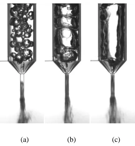
in the form of bubbles is mixed with the liquid. The two-phase flow regimes formed
flow is present at low gas to liquid flow rates ratio (GLR). As the GLR increases, the
mixture regime changes to the slug flow and then to the annular flow. In the bubbly flow,
the gas forms the discrete phase while the liquid is the continuous phase, i.e. bubbles are
injected into the liquid and dispersed. In the bubbly flow, small individual or coalesced
bubbles flow inside the liquid stream. With an increase in the GLR, the size of bubbles
increase and reaches the size of the inner diameter of the mixing chamber whereby, the
bubbly flow transforms into slug flow. With a further increase in the GLR, the gas flows
in the center of mixing chamber surrounded by an annular film of liquid on the mixing
chamber wall. Under such condition, the flow regime is considered as the annular flow.
Figure 1-2 depicts these flow regimes inside the mixing zone of an effervescent atomizer.
(a) (b) (c)
Figure 1-2: Three different flow regimes inside the effervescent atomizer (a) bubbly
flow, (b) slug flow, (c) annular flow.
The effervescent atomization process and consequently the characteristics of the resulting
spray are dependent on the atomizer internal geometry [19, 30, 46] and GLR [19, 37, 47].
47]. However, with an increase in the GLR, the internal flow changes from bubbly to slug
flow, which increases the instability of the spray [18, 42]. The slug flow due to the
presence of larger bubbles approaching the exit orifice causes significant spray pulsation
and unsteadiness [18, 48], which is not desirable in the majority of industrial applications.
Although the annular flow produces the smallest droplets, the requirement of the large
volume of pressurized gas and unstable internal flow makes it not a preferable choice.
Hence, the bubbly flow has been suggested as a better solution for a steady spray [47].
The internal mixture flow is dependent on the mixing zone cross-sectional area and the
shape of the mixing zone [8, 19]. Furthermore, in the previous studies the effect of
convergent angle [36], the exit orifice diameter [9, 17, 22, 32], the length of the exit
orifice [36, 23] and the exit orifice shape [36, 29, 35] on the droplet size were
investigated. Mostafa et al. [43] and Jedelsky et al. [30] reported that the mixing zone
length affects the radial distribution of the spray droplet size and velocity while, Sher et
al. [23] argued that the best mixing zone length for the effervescent atomization depends
on the GLR.
1.1.2
Bubble formation in a liquid cross-flow
As mentioned earlier, the generation of small-size bubbles in large quantity is desirable
for the effervescent atomization process and the bubble formation in a liquid cross-flow
has shown to be an effective way to achieve this goal. Although the main focus of the
present study is to investigate the dynamics of the internal and external two-phase flow in
an effervescent atomizer, however, to gain a better insight into the fundamental bubble
formation process in a liquid cross flow, the research has also been conducted to
investigate the bubble formation and detachment process from a novel nozzle in a liquid
cross-flow that in the future could potentially be used in the effervescent atomizer or
other industrial applications.
The bubble formation through the gas injection into a liquid cross flow has several
applications including effervescent atomization, chemical plants [49], waste water
treatment and bio- and nuclear-reactors [50, 51]. In these applications, an important
expansion in an effervescent atomizer or the reactivity and/or mass transport in chemical
and biological processes. A larger total surface area of bubbles can be achieved by
generating small-size bubbles at a higher detachment rate
Gas can be injected into a liquid stream in the co- or cross-flow configurations. Previous
studies have shown that the liquid cross-flow generates smaller bubbles at a higher
detachment rate compared to the liquid co-flow [52], which is likely due to a higher
shear. The angular orientation, size and shape of the nozzle as well as the GLR influence
the bubble formation and detachment process in a liquid cross-flow. Furthermore, in the
cross-flow configuration, the chances of bubble coalescence are lower as compared to
that in a stagnant liquid because the bubbles are continuously moved away from the
surrounding area of the nozzle or orifice [53, 54]. Coalescence is the phenomenon in
which two or more bubbles or droplets are combined through the contact surface to make
a single bubble or droplet. Since the coalescence phenomenon increases the bubble
diameter, the gas-liquid interface and the uniformity of bubbles distribution are reduced.
When the gas is injected into a liquid stream, the two-phase flow may result in one of the
following forms;
1) Formation and advection of individual bubbles into the liquid stream, i.e. no
coalescence and no mutual interactions (see Figure 1-3(a)).
2) Formation and advection of bubbles into the liquid stream that may interact and may
result in coalescence (see Figure 1-3(b)).
3) The injection of gas into the liquid stream in the form of a jet i.e. no individual bubble
formation (see Figure 1-3(c)) [16].
When the two-phase flow is comprised of individual and non-interacting bubbles, the
bubbles are smaller in size and/or far apart from each other. As the gas flow rate
increases, the bubble size increases and the individual bubbly flow regime is transitioned
into the interacting bubbly regime. In this regime, bubbles could easily deform and the
bubble collision and coalescence may also occur. A further increase in the gas flow rate
jet may breakdown into bubbles or ligaments further downstream. The above described
two-phase flow regimes in the liquid cross-flow are illustrated in Figure 1-3.
(a) (b) (c)
Figure 1-3: Different flow regimes caused by injection of gas into a liquid stream. (a)
Individual bubbly flow (b) Bubbly flow with bubble-bubble interaction (c) Jet flow.
When the gas is injected into a liquid to generate bubbles, several forces act on the
bubble. Figure 1-4 shows the main forces acting on the gas bubble during its growth and
after detachment under these conditions. During the bubble growth, once the bubble is
attached to the nozzle, these forces are, surface tension (Fs), buoyancy (FB), gas
momentum flux (FM), pressure (Fp), inertial (FI), lift (FL) and drag forces (FD) [55].
However, once the bubble detaches from the nozzle the governing forces on the bubble
reduce to buoyancy, lift and drag forces. The role of different forces is described as
follows:
The pressure force is caused by the difference between the gas pressure at the
nozzle tip and the liquid pressure. This force acts in the upward direction during
the bubble growth.
The relative motion between the bubble and the liquid resulted in the exertion of
friction force on the bubble as well as the net pressure force due to the change in
components in the direction parallel and perpendicular to the relative motion,
respectively.
Buoyancy force is generated due to the difference in the densities of gas and
liquid. It acts in the upward direction and its magnitude increases with an increase
in the bubble size. Hence, it contributes to the growth and detachment of the
bubble.
The role of the surface tension force is to keep the bubble attached to the nozzle.
It has two components; the horizontal component acts against the liquid drag
while the vertical component acts against the buoyancy force. As the bubble
grows, the magnitude of the surface tension force increases.
Inertial force also has two components in x and y direction. The growing bubble
displaces and accelerates liquid surrounding the bubble which adds mass to the
bubble [55].
Gas momentum flux force through the nozzle is a detaching upward force and
increases with an increase in the gas velocity or gas density.
(b)
Figure 1-4: Governing force acting on the bubble (a) During formation, (b) After
detachment.
The bubble formation into the liquid cross-flow from a submerged gas injector has been
studied experimentally, numerically and theoretically. Several parameters influence the
bubble dynamics, which include, size, location and shape of the bubbles, their rate of
detachment and the GLR. Several studies have investigated these parameters for
example, the characterization of the bubble size [56-58], the bubble detachment
frequency, the bubble trajectory in the liquid stream [59, 60], the bubble formation stages
[57, 61] and the mode [62, 63], and the effects of gas flow rate and liquid velocity on the
bubble formation [42, 55, 56, 58, 59, 64].
1.2 Motivation
As discussed earlier, effervescent atomizer has several advantages compared to other
atomizers. However, due to the interaction of gas and liquid flows, the internal two-phase
flow structure in the effervescent atomizer is more complex than that in single-fluid
atomizers. Despite several studies, the flow inside an effervescent atomizer is not well
understood. This is attributed to the complexities such as bubble-bubble interaction,
various locations inside the atomizer. Previous literature has shown that there is a strong
dependence of the unsteadiness in the effervescent sprays on the atomizer internal
phase flow. However, there is a lack of studies directly investigating the internal
two-phase flow and its impact on the spray characteristics. Therefore, a thorough study of this
internal two-phase flow, the parameters that control it and its relation with the spray
characteristics such as droplet size is required to improve and control the spray quality.
The performance of the effervescent atomizer depends on the bubble formation inside the
aeration zone, flow behaviour inside the mixing zone and the gas-liquid flow approaching
the exit orifice. Hence, to optimize the effervescent atomization process, understanding of
the two-phase flow dynamics in each section is crucial. Moreover, the study of a novel
submerged nozzle in a liquid cross-flow and the investigation of the underlying physical
process of bubble formation from it, would lead the potential utilization of this nozzle in
an effervescent atomizer and other related applications.
1.3 Objective
Hence, the objectives of the present study are to:
1- Investigate the effect of a novel nozzle design on the dynamics and size of the
bubbles inside a liquid cross-flow and explore the underlying phenomenon.
2- Improve understanding of the two-phase flow structure inside an effervescent
atomizer and its characterization.
3- Quantify the relation between the atomizer internal two-phase flow and the spray
characteristics.
The present study is based on an experimental research that is conducted using
state-of-the-art measurement techniques. The methodology to meet the above listed objectives is
To improve the knowledge of the bubble formation in an effervescent atomizer, first the
impact of the nozzle configuration on the bubble formation in a liquid cross-flow is
investigated using high speed imaging technique.
The same high speed imaging technique is used to study the influence of atomizer
internal two-phase flow over a wide range of operating conditions to meet the second
objective. The specific methodology includes:
Detailed investigation of the mechanics of bubble formation from the holes of the aerator into a pressurized confined cross-flow. The specific focus is on the
influence of aeration holes on the bubble size under different inlet conditions of gas
and liquid flows.
Detailed investigation of the two-phase flow regime, bubble deformation and bubble-bubble interaction inside the mixing zone. It includes bubble breakup using
bubble breakers, and the final division into finer bubbles at the exit orifice. The
flow regime inside the nozzle has a great influence on the spray behavior and the
atomization process. The two-phase flow structure reaching the exit orifice has a
direct influence on the near-nozzle liquid break-up and is a key feature that
influences the spray characteristics. Thus, understanding the behavior of gas and
liquid flow inside the mixing zone is crucial to understand and improve spray
characteristics.
The third objective, which is focused on quantifying the relation between the atomizer
internal two-phase flow and the spray characteristics, is essential for the performance
improvement of the effervescent atomizer. This allows researchers to appropriately select
the effervescent atomizer design parameters and the operating conditions that would lead
to the desired spray characteristics. This objective is achieved by measuring the droplet
size and velocity of the spray produced over a wide range of operating conditions using
1.4 Experimental measurement techniques
Different methods have been used in the past to investigate bubble formation inside the
effervescent atomizer and to characterize spray droplets generated by the effervescent
atomizers. Liu and Zheng [60] used Particle Image Velocimetry (PIV) technique to
investigate the bubble behavior and surrounding liquid in a stagnant flow. Ghaemi et al.
[42] applied Shadow-PIV/PTV technique to investigate the mechanism of bubble
formation in a liquid cross-flow. They also used particle tracking velocimetry (PTV) and
StereoPIV techniques to characterize spray droplets generated by the effervescent
atomizer. High speed imaging system has also been used to study and quantify the bubble
size inside the effervescent atomizer [37, 44, 47, 65, 66] and the spray shape and droplet
breakup process [42, 66, 67]. Some studies have used phase-Doppler particle Analyzer
(PDPA) to measure spray droplet size and velocity [19, 30, 47, 68]. It should be noted
that both droplet diameter and velocity are important parameters to characterize a spray
[42]. Among all the methods to measure the droplet velocity, an image-based technique
provides more accurate results for the spray droplets particularly when the droplets are
non-spherical in shape [69-72].
The high speed imaging technique used for bubble or droplet measurements often
employed backlit shadowgraphy technique to enhance the signal-to-noise-ratio. In this
technique, a light source along with a diffusion screen is placed behind the measurement
region to provide a uniform brighter background in the image that corresponds to the
liquid domain. This generates a good contrast between the bubbles and the background
liquid hence makes the bubble identification easy and accurate. For example, Ghaemi
[42], Sen et al [65] and Gadgile [66] have used diffused light source to illuminate the
background along with high-speed imaging system to capture the images of the gas-liquid
two-phase flow.
As mentioned earlier, the experiments in this research mainly involve the visualization
and quantification of two-phase flow within a channel with liquid cross-flow, inside an
effervescent atomizer, as well as the spray structures. The details of the state-of-the-art
imaging is conducted using a high-speed camera. This allowed tracking each individual
bubble and droplet and quantifying various bubble and droplet characteristics. Backlit
shadowgraphy with light source to illuminate the background was used during the
experiments. The experiments were conducted for various configurations under different
operating conditions and images were acquired at different sampling rates depending on
the region of interest and the configuration.
1.4.1
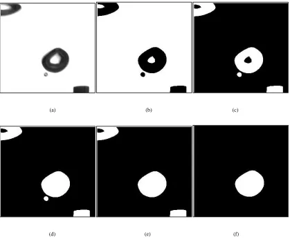
Bubble characteristics computation
The acquired images were processed using various in-house image analysis algorithms
developed in the Matlab environment (for example see Siddiqui and Chishty [59]). The
code automatically detects and tracks the bubble once it is detached from the nozzle, and
computes various bubble characteristics such as the bubble trajectory in the liquid flow,
detachment frequency, velocity, cross-sectional area and equivalent diameter. The main
steps of the image-processing algorithm are step-by-step shown in Figure 1-5. A sample
original image used as a reference is shown in Figure 1-5(a). The improvement of the
signal-to-noise ratio is the first step of the image-processing algorithm, which is achieved
by rescaling the gray-values based on the maxima and minima. The image is segmented
into a binary image in the next step by applying a threshold based on the gray-value
distribution. Figure 1-5(b) shows the corresponding image after segmentation. After
image segmentation, a series of morphological operations are performed on the binary
image that include image inversion, dilation, filling the holes and erosion, which are
illustrated in Figures 1-5(c) and (d). The noise is removed in the next step, and in the
final step, the bubbles chopped by the image edges are excluded (see Figures 1-5(e and
f)) and each bubble is detected. For each detected bubble, different properties such as
area, center of bubble, equivalent diameter and perimeter are calculated and stored in a
three-dimensional array. To compute the detachment frequency, a different algorithm was
used. In this algorithm, a region of interest was defined in the vicinity of the nozzle rim.
The signal-to-noise ratio of the image was improved next. This is followed by the
removal of noise. The algorithm continuously monitors the bubble while it is attached to
computes the equivalent bubble diameter. The recorded signal is used to compute bubble
detachment frequency.
1.4.2
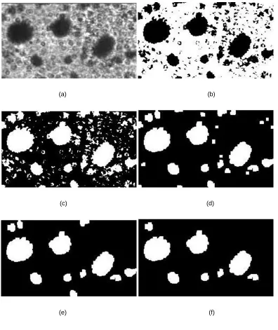
Droplet characteristics computation
An in-house algorithm in the MATLAB environment was used to automatically detect
and track the droplets and to quantify their characteristics such as droplet velocity,
cross-sectional area, perimeter and corresponding equivalent diameter. The main steps of the
image-processing algorithm are illustrated in Figure 1-6. A sample original image is
shown in Figure 1-6(a). Similar to the bubble detection, the first step of the image
processing is rescaling the gray-values based on the maxima and minima to improve the
signal-to-noise ratio. In the next step, by applying a threshold based on the gray-value
distribution the image is segmented into a binary image. Figure 1-6(b) illustrates image
after adjustment and conversion into the binary image. Figure 1-6(c) and (d) show a
series of morphological operations (image inversion, dilation, filling the holes and
erosion) performed on the binary image. In the next step, the noise is removed (see
Figure 1-6(e)). Then the droplets chopped by the image edges are excluded and hence
only those droplets that are fully visible in the image are detected in the final step (see
Figure 1-6(f)). Then different properties of droplets such as center of each droplet,
cross-sectional area, equivalent diameter and perimeter are computed and the statistical data of
the droplets was stored in a three-dimensional array. The x- and y-coordinate of the
center of each bubble in two consecutive images was used to calculate the displacement
of each droplet. The displacement of the droplet and the time interval between two
consecutive images were used to compute the velocity of the each droplet. The data in the
three-dimensional array was used to compute the droplets size and velocity in the form of
(a) (b) (c)
(d) (e) (f)
Figure 1-5: Image processing of the bubble formation to measure bubbles
characteristics (a) original image (b) image after adjustment and converting into
the binary image (c) image after inverting and dilation (d)image after filling the
holes and erosion(e) image after removing the noise (f) image after selecting the
(a) (b)
(c) (d)
(e) (f)
Figure 1-6: Image processing of spray droplets to measure droplet
characteristics (a) original image (b) image after adjustment and converting into
the binary image (c) image after inverting (d) image after erosion, dilation and
filling the holes and erosion(e) image after removing the noise (f) image after
1.5 Thesis layout
First chapter provides an introduction to the various atomization techniques and the
fundamental foundation of the effervescent atomizer. The effervescent atomization
technique with its main advantages and drawbacks are discussed. A short introduction of
two-phase flow inside the effervescent atomizer and its effect on the atomization (spray)
are also provided. Afterwards, to gain a better insight into the fundamental two-phase
flow inside the effervescent atomizer, a brief introduction of bubble formation process in
a liquid cross-flow is presented. Then the motivation and the objective of the present
study are described. A brief description of the measurement and data processing
techniques used in this study is provided at the end.
Second chapter investigates the process of bubble formation inside a liquid cross-flow
from a novel submerged nozzle. A detailed study of the effect of gas and liquid flow rates
and nozzle configuration on the process of bubble formation, bubble size and detachment
frequency is provided. An image-base analysis is also used to describe and investigate the
bubble formation and detachment process.
Third chapter focuses on the investigation of the atomization process in an effervescent
atomizer. A detailed investigation of the two-phase flow behavior inside the atomizer
under various atomizer internal geometries and operating conditions is presented. The
impact of the internal flow on the spray droplet size and velocity is investigated next.
These results are used to choose the optimal internal atomizer design for the forth
chapter.
Forth chapter focuses on the investigation of the effervescent atomization process using
a novel bubble breaker. A detailed discussion of the bubble fragmentation process using
different type of bubble breakers inside the atomizer and the corresponding spray
behavior is also provided.
Fifth chapter summarizes the conclusions of each chapter and presents an understanding
of the two-phase flow in an effervescent atomizer and lists some future
1.6 References
[1] Tricou, C., Knasiak, K., "Development of a high transfer efficiency painting
technology using effervescent atomization", (Institute for Liquid Atomization and Spray
Systems) ILASS-Americas 18th Annual Conference on Liquid Atomization and Spray
Systems, Irvine, CA, 2005.
[2] Petersen, F. J., Worts, O., Schaefer, T., Sojka, P.E., "Effervescent atomization of
aqueous polymer solutions and dispersion", Pharmaceutical Development and
Technology, 2001: 6, No. 2, 201-210.
[3] Petersen, F. J., Worts, O., Schaefer, T., Sojka, P.E., "Design and atomization
properties for an inside-out type effervescent atomizer", Drug Development and
Industrial Pharmacy, 2004: 30, No. 3, 319-326.
[4] Marshall, S. H., "Air bubble formation from an orifice with liquid cross-flow", Ph.D.
thesis, University of Sydney, Australia, 1990.
[5] Deckwer, W.D.,"Bubble column reactors", Wiley, 1992.
[6] Lefebvre, A. H., "Atomization and Sprays." New York, Hemisphere, 1988.
[7] Crowe, C. T., Michaelides, E., Schwarzkopf, J. D., "Multiphase flow handbook",
Taylor & Francis Group, 2006.
[8] Sovani, S. D., Sojka, P. E., Lefebvre, A. H., "Effervescent atomization", Progress in
Energy and Combustion Science, 2001: 27, 483-521.
[9] Lefebvre, A. H., Wang, X. F., Martin, C. A., "Spray characteristics of aerated-liquid
pressure atomizers", AIAA Journal Propulsion and Power 1988: 4(4), 293-298.
[10] Lefebvre, A. H., "A novel method of atomization with potential gas turbine
[11] Roesler, T. C., Lefebvre, A. H., "Studies on aerated-liquid atomization",
International Journal of Turbo & Jet-Engines 1989: 6, 221-230.
[12] Wang, X. F., Chin, J. S., Lefebvre, A. H., "Influence of gas injector geometry on
atomization performance of aerated-liquid nozzles", International Journal of Turbo &
Jet-Engines, 1989: 6, 271-279.
[13] Ferreira, M. E., Martins, J. J. G., Teixeira, J. C. F., "Optimization of an effervescent
atomizer to the combustion of residue Oils", (American Society of Mechanical
Engineers) ASME 2005, Heat Transfer: Volume 1, San Francisco, California, USA, July
17–22, 2005
[15] Luong, J. K., Sojka, P. E., "Unsteadiness in effervescent sprays", Atomization and
Sprays, 1999: 9, 87-109.
[14] Loebker, D., Empie, H. J., "Effervescent spraying of a medium to high viscosity
Newtonian liquid at high mass flow rates", Submitted to Atomization and Sprays, 1998.
[16] Sovani, S. D., Chou, E., Sojka, P.E., Gore, J.P., Eckerle, W. A., Crofts, J. D., "High
pressure effervescent atomization: effect of ambient pressure on spray cone angle", Fuel,
2001: 80(3), 427-435.
[17] Catlin, C. A., Swithenbank, J., "Physical processes influencing effervescent atomizer
performance in the slug and annular flow regimes", Atomization and Sprays, 2001:11(5)
575-595.
[18] Chen, S. K., Lefebvre, A. H., Rollbuhler, J., "Influence of ambient air pressure on
effervescent atomization", Journal of Propulsion and Power, 1993: 9(1), 10–15.
[19] Jedelsky, J., Jicha, M., Slama, J., Otahal, J., "Development of an effervescent
atomizer for industrial burners" Energy Fuels, 2009: 23, 6112-6130.
[20] Schmidt, F., Lorcher, M., Mewes, D. "Measured velocity profile inside a twin-fluid
atomizer generating a suspension spray", Proc. International Conference on Liquid
[21] Liu, M., Duan, Y., Zhang, T., Xu, Y., "Evaluation of unsteadiness in effervescent
atomizer sprays by analysis of droplet arrival statistics-The influence fluids properties
and atomizer internal design", Experimental thermal and fluid science, 2011:35, 190-198.
[22] Whitlow, J. D., Lefebvre, A. H., "Effervescent atomizer operation and spray
characteristics", Atomization and Sprays 1993: 3, 137–155.
[23] Sher, E., Koren, M., Katoshewski, D., Kholmer, V., "Energy consideration and
experimental study of effervescent atomizers", Proc. (Institute for Liquid Atomization
and Spray Systems) ILASS-Europe 2000, Paper II.7, Sep 11-13, Darmstadt, Germany.
[24] Jedelsky, J., Jicha, M., " Effervescent atomizer – Temporal and sptial variation of
spray structure", International Conference on Liquid Atomization and Spray Systems,
ICLASS-2006, Aug.27-Sept.1, 2006, Kyoto, Japan.
[25] Geckler, S. C. Sojka, P. E., " Effervescent Atomization of Viscoelastic Liquids:
Experiment and Modeling", Journal of Fluids Engineering, June 2008, Vol. 130,
061303-1-11.
[26] Karnawat, J., Kushari, A., "Controlled atomization using a twin-fluid swirl
atomizer", Experiments in Fluids 2006: 41(4), 649–663.
[27] Santangelo, P. J., Sojka, P. E., "A holographic investigation of the near nozzle
structure of an effervescent atomizer produced Spray", Atomization and Sprays 1995: 5,
137–155.
[28] Ferreira, M. E., Teixeira, J. C. F., Bates, C. J., Bowen, P. J., "Detailed investigation
of the influence of fluid viscosity on the performance characteristics of plain-orifice
effervescent atomizers", Atomization and Sprays 2001, 11 (2).
[29] Panchagnula, M. V., Kuta, T. J., Sojka, P. E., Plesniak, M. W., "Modifying
entrainment in ligament-controlled effervescent atomizer produced sprays", Proc.
(Institute for Liquid Atomization and Spray Systems) ILASS-Americas 1997: 35–39,
[30] Jedelsky, J., Landsmann, M., Jicha, M., Kuritka, I., "Effervescent atomizer:
influence of operation conditions and internal geometry on spray structure; study using
PIV-PLIF", (Institute for Liquid Atomization and Spray Systems) ILASS08, 2008, 1-10,
Sep 8-10, 2008, Como Lake, Italy.
[31] Jedelsky, J., Jicha, M., Slama, J., "Characteristics and behaviour of multi-hole
effervescent atomizers", Proc. (Institute for Liquid Atomization and Spray Systems)
ILASS-Europe 2004: 521–526, 2004, Nottingham, United Kingdom.
[32] Wade, R. A., Weerts, J. M., Sojka, P. E., Gore, J. P., Eckerle, W. A., "Effervescent
atomization at injection pressures in MPa range", Atomization and Sprays 1999: 9(6),
651–667.
[33] Schroder, J., Schlender, M., Sojka, P. E., Gaukel, V., Schuchmann, H. P., "Modeling
of drop sizes from effervescent atomization of gelatinized starch suspensions ", (Institute
for Liquid Atomization and Spray Systems) ILASS–Europe 2010, 23rd Annual
Conference on Liquid Atomization and Spray Systems, Brno, Czech Republic,
September 2010.
[34] Otahal, J., Fiser, J., Jicha, M., "Performance of pressure and effervescent atomizer",
Colloquium Fluid dynamics 2007, Institute of Thermomechanics AS CR, v. v. i.
(Academy of Sciences of the Czech Republic), Prague, October 2007: 24-26.
[35] Sutherland, J. J., Sojka, P. E. and Plesniak M. W., "Entrainment by
ligament-controlled Effervescent atomizer-produce spray", International Journal of Multiphase
Flow., 1997: 23(5), 865-884.
[36] Chin, J. S., Lefebvre, A. H., "A design procedure for effervescent atomizers",
(American Society of Mechanical Engineers) ASME Journal of Engineering for Gas
Turbines Power 1995: 117, 226–271.
[37] Lorcher, M., Schmidt, F., Mewes, D., "Flow field and phase distribution inside
effervescent Atomizers" 9th International Conference on Liquid Atomization and Spray
[38] LiJuan, Q., JianZhong, L., "Modeling on effervescent atomization: A review",
Science China Physics, Mechanics & Astronomy, December 2011: 54(12), 2109–2129.
[39] Kolev, N. I., "Multiphase Flow Dynamics 2, Thermal and Mechanical Interactions",
Springer-Verlag Berlin Heidelberg, 2002.
[40] Roesler, T. C., "An experimental study of aerated-liquid atomization", PhD thesis,
Purdue University, 1988.
[41] Roesler, T. C., Lefebvre, A. H., "Photographic studies on aerated liquid atomization,
combustion fundamentals and applications", Proceedings of the Meeting of the Central
States Section of the Combustion Institute, Indianapolis, Indiana, Paper 3, 1988.
[42] Ghaemi, S., "Investigation of Effervescent Atomization Using Laser-Based
Measurement Techniques", Thesis in University of Alberta, 2009.
[43] Mostafa, A., Fouad, M., Enayet, M., Osman, S., "Measurements of spray
characteristics produced by effervescent atomizers". AIAA/ASME/SAE/ASEE Joint
Propulsion Conference and Exhibit, July 11-14, 2004, Fort Lauderdale, Florida.
[44] Gomez, J., Fleck B., Olfert J., McMillan J., " Characterization of a horizontal
two-phase spray from an effervescent atomizer", (Institute for Liquid Atomization and Spray
Systems) ILASS-Europe 2010, 23rd Annual conference on Liquid Atomization and
Spray Systems, Brno, Czech Republic, September 2010.
[45] Kleinstreuer, C., "Two-Phase Flow Theory and Application." New York:
Taylor&Francis 2003.
[46] Jedelsky, J. and Jicha, M. ,"Novel modifications of twin-fluid atomizers:
performance, advantages and drawbacks", (Institute for Liquid Atomization and Spray
Systems) ILASS – Europe 2010, 23rd Annual Conference on Liquid Atomization and
Spray Systems, Brno, Czech Republic, September 2010.
[47] Huang, X., Wang, X., and Liao, G. "Visualization of two phase flow inside an