Vol. 4, Issue 1, January 2015
FPGA Design of 8 bit 4×4 Crossbar Switch for
Multi Processor System on Chip Using Round
Robin Arbitration Algorithm
Sajad Ahmad Ganiee1, Shabeer Ahmad Ganiee2, Jehangir Rashid Dar3
Senior Faculty, NIELIT, Srinagar, India 1
Assistant Professor, Department of E&C, IUST Awantipora, Srinagar, India 2
Junior Research Fellow, Department of Physics, Govt. Degree College for Women, Anantnag, India 3
ABSTRACT: The Network-on-Chip (NoC) is dominating now days. The NoC is characterized by the topology, routing, and flow control. The work presents Verilog implementation, modeling and synthesis of 8-bit 4 × 4 crossbar switch for virtual channel router. The crossbar components are widely used in router and switches. A crossbar switch may serve as switching fabric to provide a non blocking network configuration. Mainly crossbar is used as an interconnection network in NoC. Crossbar switch is a fully connected network, where each input is connected to each output. Crossbar switch is of great interest in packet switch designs. In virtual channel router minimum flit size is 8-bit. We have also designed arbitration module called DPA cell and 8 bit fabric module for crossbar. As flit size is 8- bit for virtual channel router we have implemented 8- bit 4 × 4 switch. In this paper rotating round robin arbitration algorithm with the help of DPA had been also implemented Hence our proposed arbiter is suitable for NoC design which needs high speed cross bar switches and router in them.The design is synthesized on Vertex 7 and maximum operating system achieved 1.1 GHz. Using parallel bit data transfer we have archived faster data transmission rates. Critical path delay of 8-bit 4x4 crossbar switch is 4.996ns.
KEYWORDS:Network on Chip (NoC), System on Chip (SoC), Scheduler, Routing, and Crossbar.
I. INTRODUCTION
The multiprocessors System on chip (SoC) designs have more than one processor and huge memory on the same chip. System on chip (SoC) consists of hardware cores and software cores, multiple processors, embedded DRAM and connectors between cores. System on a chip (SoC) technology is the packaging of all the necessary electronic circuit and parts for a "system" (such as a cell phone, digital camera, and laptop) on a single integrated circuit, generally known as a microchip. The integration of the transistor in a single chip greatly increases the performance of a system, efficiency while reduction in size.According to Moore’s law that integration density gets doubled every two years so that the complexity of the integrated system increases by keeping the used chip area constant [1]. Network-on-chips (NoC) has advantages on architecture, performance, reusability and scalability than traditional bus-based system-on-chip. The solution to scalable and efficiently connect on-chip components is a packet-switched on chip network [2, 3, 4]. A NoC consists of a high-speed router at each node, connected by links to its neighbours. The architecture and dataflow control will affect the design of arbiter of NOC significantly. Many current multi-core systems are small (2-8 cores), and hence, a simple common bus suffices to connect the various components. However, chips with hundreds or thousands of cores are likely to be common place [5, 6] Connecting so many cores with a bus is not scalable because electrical loading on the bus significantly reduces its operational speed and the shared bus cannot support the
Vol. 4, Issue 1, January 2015
packets among those interfaces [7]. A crossbar switch may serve as switching fabric to provide a non blocking network configuration [8]. Crossbars are one of the key components in most communication switches used in today’s networks. In general, switch networks are composed of four parts: switching engine, switch fabric, queuing discipline and forwarding technology [9]. The switching engine is responsible for identifying the destination for the input packets. The switch fabric forwards the packets to the output ports with different scheduling methods and forwarding techniques. The arbitration plays a crucial role in determining performance of bus-based system, as it assigns priorities, with which processor is granted the access to the shared communication resources. The arbitration should guaranteed the fairness in scheduling, avoid starvation, and provide high throughput [10]. The NoC's switches should provide high speed and cost-effective contention resolution scheme when multiple packets from different input ports compete for the same output port. A fast arbiter is one of the most dominant factors for high performance NoC switches [11].In the conventional arbitration algorithms there are some drawbacks such as bus starvation problem and low system performance. The bus should provide each component a flexible and utmost share of on-chip communication bandwidth and should improve the latency in access of the shared bus. The performance of SoC is improved using the probabilistic round robin algorithm with regard to the parameters.
II. CROSSBAR FABRIC MODULE
Fig.1 Crossbar fabric module
The crossbar fabric is responsible for physically connecting an input port to its destination output port based on the grant issued by the scheduler. The design of the crossbar fabric is shown in Figure 1.In other words the crossbar-based fabric switch is the dominant architecture for today’s high-performance packet switches [12] [13]. The fabric of a crossbar-based packet switch can be either unbuffered [12] or internally buffered [13]. The similarity between these two variants lies in the quadratic growth of their cost with the number of switch ports. Additionally, both architectures require a sophisticated input queuing structure, known as the virtual output queuing (VOQ) to achieve acceptable performance [14]. Unbuffered crossbar fabrics are cheaper than their buffered counterparts since they contain no internal buffers. However, they are hard to scale due to the high-computational complexity and centralized nature of their scheduling [14].
First request comes from the input ports to the crossbar scheduler of the switch for the destination output port. The scheduler grants a request based on a priority algorithm that ensures fair service to all the input ports. Once a grant is issued, the crossbar fabric is configured to map the granted input ports to their destination output ports. The crossbar fabric module in the design is responsible for physically connecting an input port to its destined output port, based on the grants issued by the scheduler. The inputs of fabric (except for the cntrl input) are connected to the input port modules of our switch. The outputs of fabric are connected to the output ports of the switch. The fabric makes the appropriate connection between each input and its corresponding output..Here fabric comprises of16) control lines four (4) control lines associated with each input shown as xxxx in the figure 1. If one of the control lines 0,4,8,12 are high at a time the input data of the four(4) input ports will appear at output port 1.Similarly if one of the control lines 1,5,9,13 are high then input data of the four(4) input will appear at output port 2 .However we can send to 8 bit data to all four ports at a time by making their respective control lines high means if we make the control lines 0,5,9,13 high the data can be accurately transferred to the output ports 1,2,3,4.In 4×4 crossbar fabric it is clear we are sending data to any
x,x,x,x
x,x,x,x
x,x,x,x
x,x,x,x
Input1
Input2
Input3
Input4
Input1
Input2
Input3
Input4
CROSSBAR FABRICVol. 4, Issue 1, January 2015
output port keeping the required control lines high but we are facing a problem without proper arbitration .If two input ports are requesting to send data to the same output port. As a result we cannot send data because of interfering (Blocking) between two ports requesting for same output port. This problem is solved by using an arbitration technique called round robin arbitration discussed in V.
III. CROSSBAR SWITCH MODEL
Crossbar switch (also known as cross point switch or matrix switch) is a switch connecting multiple inputs to multiple outputs in a matrix manner. Originally the term was used for a matrix switch controlled by a grid of crossing metal bars and later was broadened to matrix switches. The point of intersection of horizontal and vertical lines is known as crosspoint.At each cross point is a switch when closed it connects one of ‘M’ inputs to one of ‘N’ outputs. Collection of crossbars can be used to implement multilayer or blocking switches .A crossbar switching system is also known as co-ordinate switching system. A simple model of crossbar switch is shown below in Figure 2.Each horizontal bus is connected to an input port and each vertical bus is connected to an output port .Crossbar switches are fully connected switches. Therefore, in a crossbar switch, there is a direct path from every input to every output. Crossbars provide a direct connection between each input and output port.
Fig.2 Crossbar
Fig.2 Crossbar model
The speed of the crossbar depends on whether input queues or output queues are used. In case of input queues, the input and output port controllers have the advantage of working with merely the speed of the links. If output queues are utilized, the switch fabric has to be fast enough not to cause contention at the output ports.
IV.COMPLETE STRUCTURE OF 4 x 4 CROSSBAR SWITCH
The 4 x 4 crossbar switch is a four input, four output message router that routes a message entering on an input port to an output port selected by the message header. The 4 x 4 crossbar switch employs virtual cut-through routing technique [15]. If an output port is not already occupied by another message, the head of the incoming is advanced into this output port as soon as the head of the message is received and decoded. The message is then moved forward through this established link until the link is closed by the tail of the message. If the selected output port is blocked by another message then 4 x 4 crossbar switch will automatically reroute the message around the busy output port. This automatic routing around a busy port is known as random routing' [16]. If random routing fails to find an unoccupied output port, the incoming message is blocked and stored into the memory buffer at the input port. The 4 x 4 crossbar switches also supports broadcast routing. If the head of the incoming message is decoded to be a broadcast message, the message is then routed to the multiple output ports. In the 4 x 4 crossbar switch a total interconnection of inputs and outputs is implemented. As a result each input can be directly connected to all outputs. All these connections are independent of each other and therefore can function simultaneously without interfering each other. The 4 x 4 8 bit crossbar switch has four independent data ports and is therefore capable of performing four simultaneous communications. The 4 x 4 crossbar switch has four first-in first-out (FIFO) memory buffers, four control units. a crossbar, an arbiter and 8 bit input data. The control units and the arbiter are driven by a single central clock signal. The main reason for the 4 x 4 crossbar switch having only one FIFO buffer per input port is that this buffering scheme allows for a high speed design. If multiple buffers are used for each of the input ports. Each output port is required to connect to multiple loads. The impedance of the connection may becorne unstable. This leads to the degradation of the data transfer rate because the
Vol. 4, Issue 1, January 2015
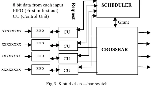
data transfer is encumbered by the need to cater for different numbers of connections and variable loads. Each FIFO has its own clock signals to clock data into and out of the memory buffer. The crossbar is pure combinational logic thus it is not driven by any clock signal. The main function of the four FIFO's is to provide data buffering for the 4x4crossbar switch. If an incoming message is blocked due to the selected output port being already occupied, the incoming message is stored in the FIFO until the selected output port is free. Each FIFO is controlled by separate clocked read and write signals. Therefore, each FIFO is able to store more than two short messages. The 8 bit input data sends request to the scheduler and grant is received if the requested is empty accordingly data is send to the requested port. As soon as the first message is sent off the switch, the second message is ready to make a connection to a output port immediately. The reason for doing this is to keep the output ports as busy as possible. The complete structure of 4x 4 is shown below in Figure 3
Fig.3 8 bit 4x4 crossbar switch
V.ARBITRATION
Arbitration sets the connections to be made between ingress and egress ports of the cross bar switch of a data switching system. A weight parameter is used for each pair of ingress and egress ports. Connection requests are generated indicating ingress ports to be connected to egress ports. A selection is made among conflicting connection requests to produce a connection proposal for each egress port. Any connection request for which respective weighting parameter is zero isn’t selected. When one of the connection requests is realized, the weight parameter corresponding to this connection is decreased by one. All the weight parameters for a given egress port are reset to default values in the case that there are no connection requests for that egress port with non zero weights. Since different types of arbitrations exist in switching mechanism but in this paper a typical arbitration technique known as Round Robin Arbitration Technique discussed as
A. Designing of Round Robin Arbitration
Packets with the same priority and destined for the same output port are scheduled with a round-robin arbiter. Supposing in a given period of time, there was many input ports request the same output or resource, the arbiter is in charge of processing the priorities among many different request inputs [17]. The arbiter will release the output port which is connected to the crossbar once the last packet has finished transmission. So that other waiting packets could use the output by the arbitration of arbiter. A round-robin arbiter operates on the principle that a request which was just served should have the lowest priority on the next round of arbitration. Depending upon the control logic arbiter generates select lines for multiplexer based crossbar and read or write signal for FIFO buffers. In other words in round robin arbitration, the arbiter scans all the channels and the first one that is ready to transmit, say channel ‘i’, is selected to send one flit. The next cycle the scanning process starts with channel (i+1). This method is evidently fair and no starvation can occur. Round robin arbiter grants access to any bus on rotatary basis like a rotary switch as shown in Figure 4.Active 1 is requesting a bus access the arbiter grants access to it. After this request is over the arbiter is turned to Active 2 and grants access to it and accordingly the arbiter grants access in a clockwise fashion.
xxxxxxxx
xxxxxxxx
xxxxxxxx
xxxxxxxx
Grant
CROSSBAR SCHEDULER
CU
CU
CU
CU FIFO
FIFO
FIFO
FIFO
8 bit data from each input FIFO (First in first out) CU (Control Unit)
R
e
q
u
e
Vol. 4, Issue 1, January 2015
Fig.4 Arbiter as rotating switch
However, the IP router latency tends to be uniformly increased for all flits.To alleviate this negative effect we can make the following amendment: the scanning process will move to the next ready channel only if the current channel has just sent a tail flit. In other words, the arbiter will prefer the worm that is currently flowing out of the router. When this worm has drained out completely, the simple round-robin policy is used. Round robin matching (RRM) overcomes the unfairness of random matching by granting requests and accepting grants according to a round robin priority scheme [18, 19]. There are three steps in this algorithm shown in Figure 15 [20]
a) In the Request step, each input sends a request to scheduler to know whether output port is free or not.
b) In the Grant step, an output that has received any requests grants the one request that appears next in a fixed round robin schedule starting from the highest priority element. The priority round robin of the output is then incremented one step beyond the granted input;
c) In the Accept step, an input that has received grants accepts the grant that appears next in a fixed round robin schedule starting from the highest priority element. The priority round robin of the input is then incremented one step beyond the accepted output.
Now in the results of 8 bit 4×4 crossbar fabric it is clear we are sending data to any output port keeping the required control lines high but we are facing a problem if two input ports are requesting to send data to the same output port. As a result we cannot transfer data because of conflict between two ports requesting for same output port. This problem is solved by round robin arbitration. In this technique the last two bits of 8 bit data are used to decide the destination port address. Four control lines are linked with each input port. For example in Figure 3 if the last two bits four input 8 bit data are 00,01,10,11 then we can send data to the output ports 1,2,3,4 respectively by keeping the control lines 1,5,10,15 high as shown in Table 1. If the last two bits of the 8 bit data are same we can send only one input data during first clock and the second input with same last two bits during the second clock and their priorities are decided by diagonal priority arbiter discussed in next section.
Table.1 Shows input output data flow in detail
Input port Port address Arbitration bits Select line Output port
Port 1 11000001 01 1 Port 2
Port 2 01011010 10 6 Port 3
Port 3 11001100 00 8 Port 1
Port 4 00110011 11 15 Port 4
Active4
Active3
Vol. 4, Issue 1, January 2015
VI.CROSSBAR SCHEDULERS
Crossbar schedulers accepts one request from each input port and grants some of those requests, during each packet time according to a priority algorithm. Its main goal is to be fair to all the inputs means which packet among the packets having same arbitration bits is granted. There are many ways of implementing crossbar scheduler:
a) Ripple carry arbiter (RCA).
b) Rectilinear Propagation arbiter (RPA) c) Diagonal Propagation arbiter (DPA)
As, there are some disadvantages in RCA, RPA like delay is very large and priority rotations are also not possible ,so we move on to DPA .
A) Diagonal Priority Arbiter (DPA)
Here in this crossbar switch we are implementing DPA arbiter as delay is less and priority rotations are also possible.DPA design is that there are some cells in the two dimensional propagation arbiter that are independent of one another, in the sense that granting one of them does not prevent granting the others.[21].
Fig.5 3x4 DPA (Diagonal priority arbiter)
The cells that are independent of one another are put in diagonal rows. In the above figure cell (1, 1) ,cell (4, 2),cell(3,3) and cell(2,4) are diagonally connected therefore these cells are independent, so is the case with (2,1),(1,2),(4,3) and (3,4) diagonal cells. The arbitration process in the DPA architecture begins by considering the first diagonal. If there is a request for every cell in the first diagonal of Figure 5, they can all be granted. Then, in the next time slot, the arbitration process moves to the second diagonal. The cells with requests in the second diagonal will only receive grants if no cells on the top or on the left of them have yet received grants. The ripple-carry design gives the priority to the cells that are higher and to the left. Similarly, in the DPA architecture the highest priority is always given to the cells in the first diagonal. But it will rotate the priorities by adding mask active window [21].
In order to rotate the priorities at the same time Hurt et al have found architecture to overcome this problem. In this case the first (n-1) diagonals of n×nDPA after the last row are repeated consider Figure 5. The X signals of the first column and W signals of first diagonal are set to logic one. At every time n2 cells are active as shown shown by the bold window in the Figure 5.The cells in the first diagonal of the active window has the highest priority. Shaded cells are the cells which receive grants and the cells with bold squares receive requests. The active window moves one stop in every time slot to rotate the priority. Any cell inside the active window will get its priority turn after when the active window rotate through n cells. To implement priority rotations vector P is introduced[21]. The (2n-1) elements of vector P are named pr.
Received Grant
Received Request
1,1
2,1
3,1
4,1
4,2
1,2
2,2
3,2
3,3
4,3
1,3
2,3
2,4
3,4
4,4
1,4
Vol. 4, Issue 1, January 2015
The algorithm for priority rotations is: • set P = “111111110000000”. • if P = “000000011111111” then • set P = “111111110000000” • else
• Rotate P one position to the right. (This step is like moving the window one step down.) • At every time slot only n2 cells are active.
So , by going through these three arbiters ,we came to know that DPA is the best design out of three arbiters,so here we are designing the same arbiter and comparing my results with the results given in Table 3.
Table.2 Difference between RCA,DPA,DPA.
RCA RPA DPA
Combinational feedback loop exists. No feedback loop is there No feedback loop is there
Priority rotations are not possible. Priority rotations are possible. Priority rotations are possible
Delay is (n-1)d. Delay is 2 (n-1)d+2t. Delay is nd +t.
VII.SIMULATION RESULTS
1) Two ports Requesting for same output port
This simulation result of 4×4 crossbar switch has four 8 bit inputs with the first two inputs having the same last two bits and the other two inputs have different last two bits. It means first two inputs having same last two bits ‘00’ are requesting to send data to same output port 1.Among these two inputs we are sending the data of only one port during first clock and the second input during second clock with their priority decided by diagonal priority arbiter(DPA) and having their respective control lines high. The third and fourth inputs with different last two bits 01 and 10 send data to the output ports first and third since these are the alone ports requesting at the same time control lines 8 and 14 must be high as shown in Table 3 and in simulation result in Figure 6
Table.3 Two input ports requesting for same output port
Input address Arbitration
bits
Port Request
Control line
1st clock 2nd clock
11001100 00 1 0 11001100 00111100
00111100 00 1 4 00110001
00110001 01 2 9 11001110
Vol. 4, Issue 1, January 2015
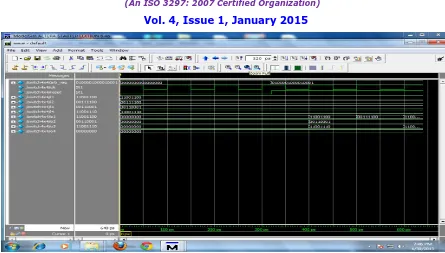
Fig. 6 Simulation result of 4×4 crossbar switch with first two inputs same last two bits.
2) All ports requesting for same port
In this result all the four inputs have the same last two bits and are requesting for output port 4. We can send data to output port 4 in four clock cycles respectively provided the control lines 3,7,11 and 15 must be high as shown in Table 4 and in simulation result of Figure 7
Table 4 All input ports requesting for same output
Input address Arbitration bits Port Request Control line
Clocks
1st clock
2nd clock
3rd clock
4th clock
00110011 11 4 3
10101011 11 4 7
11110011 11 4 11
00000011 11 4 15 101010
11
111100 11
000000 11
Vol. 4, Issue 1, January 2015
Fig 7 Simulation result of 4×4 crossbar switch with all four inputs same last two bits.
VIII.ANALYSIS
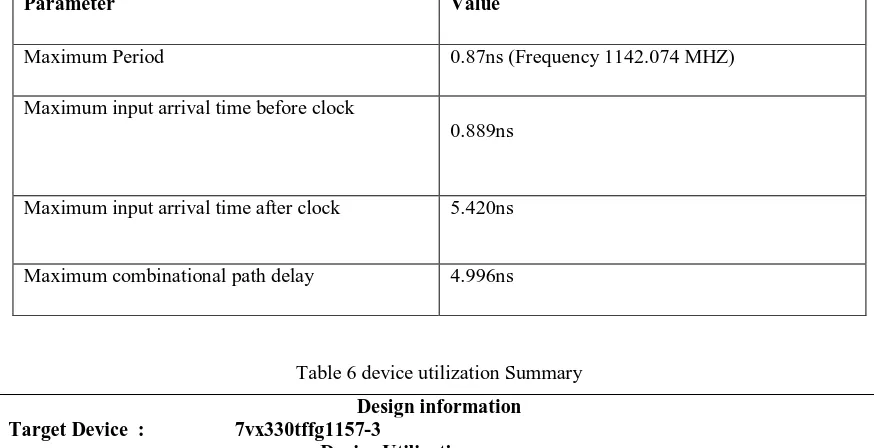
The Crossbar switch has been synthesized on Vertex 7 FPGA Board using Xilinx. We present an analysis of the design implementation and speed of 4×4 crossbar switch. The discussions illustrate a fact that a 4×4 crossbar switch with the help of diagonal priority arbiter (DPA) we are faster transmission data rates. The detailed time summary is shown in Table 5
Table 6 The detailed time summary
Parameter Value
Maximum Period 0.87ns (Frequency 1142.074 MHZ)
Maximum input arrival time before clock
0.889ns
Maximum input arrival time after clock 5.420ns
Maximum combinational path delay 4.996ns
Table 6 device utilization Summary
Design information Target Device : 7vx330tffg1157-3
Device Utilization summary
Logic Utilization Used Available Utilization
Vol. 4, Issue 1, January 2015
D
e
la
y
in
se
c
on
ds
Now we will compare few parameters power and critical path delay analysis of 8 bit 4×4 Crossbar switch with previous crossbar switches.
Table 7 Delay analysis of 8 bit 3x2, 6×6 and 4×4 crossbar switches
The graphical representation of delay is shown in Fig. 8.The Y-axis reads delay in nanoseconds and X-axis represents the type of crossbar switch
0 2 4 6 8 10 12 14
3×2 Crossbar 6×6 Crossbar 4×4 Crossbar
Fig.8 Delay Comparism of crossbar architectures
IX.CONCLUSION
This project has implemented HDL Modeling and synthesis of 8-bit, 4 x 4 crossbar switch. We have also designed arbitration module called DPA cell and 8 bit fabric module for crossbar. As flit size is 8- bit for virtual channel router we have implemented 8- bit 4x4 crossbar switch. In this we had also implemented rotating round robin arbitration algorithm with the help of DPA. Round Robin Arbitration scheme guarantees that all input request are treated fairly. The design is synthesized on Vertex 7 series. Using parallel bit data transfer we have archived faster data transmission rates. Critical path delay is 8-bit 4x4 crossbar switch is 0.876ns (Maximum Frequency: 1142.074MHz).
REFERENCES
[1] Resve saleh ,steve wilton,system on chip: Reuse and integration,Proceedings of the IEEE vol.94,No.6,june 2006 [2] W. J. Dally and B. Towles. Route packets, not wires: On-chip interconnection networks
[3] L. Benini and G. D. Micheli. Networks on chips: A new SoC paradigm. Computer, 35:70–78, Jan 2002 [4] T. Bjerregaard et al. A survey of research and practices of network on-chip. ACM Computing Surveys, 2006. [5] S. Borkar. Thousand core chips: a technology perspective. DAC-44, 2007.
[6] J. Owens et al. Research challenges for on-chip interconnection networks. IEEE MICRO, 2007. [7] C. Partridge et al., “A 50-Gb/s IP router,” IEEE/ACM Trans Networking,vol. 6, pp. 237–248, June 1998.
No. of slice LUT,s 124 204000 0.6%
No. of LUT flip flop pairs 127 127 100%
No. of Bonded IOB,s 82 600 13%
No. of fully used flip flops 122 127 96%
Parameter 3x2 Crossbar switch 6×6 Crossbar switch 4x4 Crossbar switch
Delay(ns) 4.34 12.89 4.996
D
e
la
y
in
n
a
nos
e
c
on
Vol. 4, Issue 1, January 2015
[8] J. Duato, S. Yalamanchili, and L. Ni, Interconnection Networks: AnEngineering Approach. Los Alamitos, CA: IEEE Comp. Soc. Press, [9] H. J. Chao and B. Liu, High Performance Switches and Routers.Wiley-Interscience, 2007.
[10] Yun-Lung Lee, Jer Min Jou and Yen-Yu Chen,a High Speed and decentralized arbiter Design for NoC[J],350-353 [11] Eung S.Shin,Vincent 1.Mooney III and George f.Riley ,Round Robin arbiter .Arbiter Design And Generation,ISSS’02 [12] N. McKeown and al., “The Tiny Tera: A Packet Switch Core,” IEEE Micro, pp. 26–33, January/February 1997. [13] F. Abel and al., “A Four-Terabit Packet Switch Supporting Long RoundTrip Times,” IEEE Micro, vol. 23, no. 1, 2003.
[14] N. McKeown, “Scheduling Algorithms for Input-Queued Cell Switches,” Ph.D. dissertation, University of California at Berkeley
[15] P. liermani and L. lileinrock. Virtual Cut-Through: A New Cornputer Communication SlVitching Technique. Cornputer Networks.pages 267 [16] Cypress Semiconductor Corporation. Raceway Crossbar..July 1995.
[17] International Journal of Engineering and Advanced Technology (IJEAT) ISSN: 2249 – 8958, Volume-1, Issue-6, August 2012 [18] N. McKeown, “The iSLIP scheduling algorithm for input- queuedswitches,” IEEE Transactions on Networking, vol. 7, no. 2, pp. 188- 201,April 1999.
[19] N. McKeown, M. Izzard, A. Mekkittikul, B. Ellersick, and M.Horowitz, “The Tiny Tera: A small, high bandwidth network switch,” IEEE Micro, January/February 1997, pp. 26-33.