Effect of Stresses on Square and Rectangular Helical Spring
Dr.S.V.Bhalerao
1, Ashish M. Choube
2, B.E.Gajbhiye
31
Professor, 2Asst Prof,3Asst Prof
Mechanical Engineering Department, Jawaharlal Darda Institute of Engg&Tech,Yavatmal Email- [email protected],
Abstract—Springs are elastic bodies (generally metal) that can be twisted, pulled, or stretched by some force. They can return to their original shape when the force is released. In other words it is also termed as a resilient member. Generally springs are work on the principle of fluid displacement on both the compression and expansion cycle. Helical springs are used for different applications like in automobile, in brakes and clutches, in watches and toys etc. This work deals with the stress analysis of different cross sectional helical springs and its validation with analytical method.
Keywords-Circular Helical Spring, Square spring,Stress Analysis, etc.
1. INTRODUCTION
A coil is a thing which mainly used in different springs which stores energy or provides a force over a distance by elastic deflection. Energy may be stored in a compressed gas or liquid, or in a solid that is bent, twisted, stretched, or compressed. The energy is recoverable by the elastic return of the distorted material. Spring structures are characterized by their ability to withstand relatively large deflections elastically. The energy stored is proportional to the volume of elastically distorted material, and in the case of metal springs, the volume of distorted material is limited by the spring configuration and the stress-carrying capacity (elastic limit) of the most highly strained portion. For this reason, most commercial spring materials come from the group of high-strength materials, including high-carbon steel, cold-rolled and precipitation-hardening stainless and nonferrous alloys, and a few specialized nonmetallic such as laminated fiberglass. Thus spring design is basically an analysis of machine elements which undergo relatively large elastic deflections and are made of materials capable of withstanding high stress levels without yielding.
For FE analysis, a circular helical spring of material Carbon steel SAE 1050 is considered in which one side of the spring is fixed and axial load is applied at the other end of the spring. The dimensions of circular spring considered are as follow.
Wire diameter (d) =8mm Mean diameter (D) =46mm Pitch (p) =11mm
Spring index(C) =5.75 Axial force (F) =1000N
Here, different cases of circular springs are considered by changing free length of spring. The analysis is carried out using finite element method with FE software ANSYS. Shear stress and deflection are calculated analytically and compared with FE results. After, circular springs are converted into square and rectangular springs with keeping same material and
same volume. Here breadth and width of square and rectangular spring can be calculated by using following cases
1. b=h 2. b=1.5h 3. b=2h 4. b=2.5h
Analysis of square and rectangular helical springs is carried out using FE method. Shear stress and deflection are evaluated analytically and compared with FE results.
2. DETERMINATION OF STRESSES FOR
CIRCULAR, HELICAL SPRINGS USING
ANALYTICAL METHOD
For analysis of circular helical spring, following dimensions are considered. Wire diameter (d) =8mm, Mean diameter (D) =46mm, Pitch (p) =11mm, spring index (C) =5.75, Wahl’s correction factor (Ks) =1.263, Free length (Lf) =124mm, Axial force (F) =1000N for stress analysis and Axial force (F) =1N for buckling analysis. From free length and pitch, number of turns are calculated as n=10.27
For material Carbon steel SAE 1050, following material properties are used as shown in Table I.
TABLE I: MATERIAL PROPERTIES OF CARBON STEEL SAE 1050
Deflections (δ) and shear stresses ofcircular helical spring are evaluated by equation 2.1 to 2.2
4 3 8 Gd n FD =
δ ………... (2.1)
Sr.No. Symbols Parameters Values 1 E Young’s modulus 2.1 × 10⁵Mpa
2 µ Poisson’s ratio 0.295
3 max 8 d FD Ks π
τ = ……... (2.2)
3. DETERMINATION OF STRESSES OF SQUARE
AND RECTANGULAR HELICAL SPRINGS USING ANALYTICAL METHOD
Here, Circular springs are converted into square and rectangular spring by keeping the same volume.Breadth and width can be calculated by using aboce cases.
1. b=h
2. b=1.5h
3. b=2h
4. b=2.5h
For analysis of square helical spring, following dimensions are considered.
For b=h, Breadth (b=7mm), Width (h=7mm) For b=1.5h,Breadth (b=8.7mm), Width (h=5.8mm) For b=2h, Breadth (b=10mm), Width (h=5mm) and For b=2.5h,Breadth (b=11.18mm), Width (h=4.47mm) Mean diameter (D) =46mm, Pitch (p) =11mm, Free length (Lf) =124mm, Axial force (F) =1000N for stress analysis and Axial force (F) =1N for buckling analysis. From free length and pitch, number of turns are calculated as n=10.27Table I shows the material properties forsquare helical springs.
Here deflection and shear stresses for square and rectangular spring are evaluated analytically by using equation
2.3 to 2.6.
4 3 66 . 5 Gh nFD =
δ ……… (2.3)
75 . 2 75 . 0 max 8 . 4 h FD =
τ ………..… (2.4)
G h b h b nFD 3 3 ) 2 2 3 ( 83 . 2 + =
δ ……….. (2.5)
2 1 max bh K FD = τ ………..……(2.6)
4.DETERMINATION OF STRESSES AND BUCKLING
LOAD FOR CIRCULAR, SQUARE AND
RECTANGULAR HELICAL SPRINGS USING FE
APPROACH
For FE analysis, CAD model of circular, square and rectangular are created and imported in FEA software ANSYS.For stress analysis, constraints are applied at the one side of spring and the force is applied on the center of other side of spring. By giving these conditions, deflection and shear
Fig.1 Deflection contour for circular springs
Fig.2 Shear stress contour for circular springs
Fig.4 Shear stress contour for square springs (b=h)
Fig.5 Deflection contour for square springs (b=1.5 h)
Fig.6shear stress contour for square springs (b=1.5 h)
Fig.8 Deflection contour for rectangular springs (b=2h)
Fig.7 Shear stress contour for rectangular springs (b=2h)
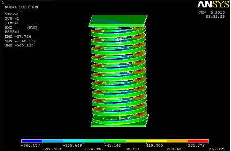
Fig.10 shear stress contour for square springs (b=2.5 h)
5. DISCUSSION AND CONCLUSION
[image:4.595.305.565.347.390.2]The analytical and FE results of circular, square and rectangular coils determined with varying its free length are given in Table II to Table VI.
TABLE II: ANALYTICAL AND FE RESULTS OF CIRCULAR HELICAL SPRING
CASES DEFLECTION (mm) SHEAR STRESS
(N/mm2)
THEORY FEA THEORY FEA
Lf=225 46 45 289 265
Lf=200 41 42 289 269
Lf=150 30 30 289 265
Lf=124 24 24 289 262
Lf=75 14 15 289 260
Lf=225 8 9 289 261
TABLE III: ANALYTICAL AND FE RESULTS OF SQUARE HELICAL SPRING (b=h=7)
CASES DEFLECTION (mm) SHEAR STRESS
(N/mm2)
THEORY FEA THEORY FEA
Lf=225 56 56 402 325
Lf=200 49 49 402 331
Lf=150 36 37 402 330
Lf=124 29 28 402 326
Lf=75 17 16 402 352
Lf=225 12 11 402 332
TABLE IV: ANALYTICAL AND FE RESULTS OF RECTANGULAR HELICAL SPRING (b=1.5h)(h=5.8,b=8.7)
CASES DEFLECTION (mm) SHEAR STRESS
(N/mm2)
Lf=124 30 30 340 321
Lf=75 17 17 340 308
Lf=225 10 10 340 293
TABLE V: ANALYTICAL AND FE RESULTS OF CIRCULAR HELICAL SPRING(b=2h)(h=5,b=10)
CASES DEFLECTION (mm) SHEAR STRESS
(N/mm2)
THEORY FEA THEORY FEA
Lf=225 67 69 374 394
Lf=200 59 60 374 347
Lf=150 43 43 374 402
Lf=124 35 34 374 352
Lf=75 20 19 374 334
Lf=225 12 13 374 347
TABLE VI: ANALYTICAL AND FE RESULTS OF CIRCULAR HELICAL SPRING (b=2.5h)(h=4.5,b=11.25)
CASES DEFLECTION (mm) SHEAR STRESS
(N/mm2)
THEORY FEA THEORY FEA
Lf=225 76 78 391 369
Lf=200 67 65 391 354
Lf=150 49 48 391 446
Lf=124 40 38 391 363
sharp edges. This is further increases with increase in breadth to width ratio. From this analysis, it is observed that circular springs are more preferable than square and rectangular spring.
REFERENCES
[1]B. D. Shiwalkar, Design Data for Machine Elements. 2012 Edition, pp79-92.
[2]K. Mahadevan and K. Balaveera Reddy, Design Data Hand Book. Third edition.pp 138-160.
[3]Lingaiah K., Machine Design Data book, Second edition. pp 20.1-20.33.
[4]Dr. P. C. Sharma and Dr. D. K. Aggarwal, “Machine Design”, millennium edition, pp.307-384.
[5]R. S. Khurmi and J. K. Gupta, “Machine Design”, S. Chand publication, pp.820-844.
[6]Max Forgeil, “Machine Design Problem Solver”, Research association.
[7]V. Brijpuria, 2013, “Analysis of closed coil helical spring subjected to heavy duty” IJEA, vol-1, Issue-4, pp 50-55. [8]Tausif M. Mulla, “Finite element analysis of helical coil
compression spring for three wheeler automotive front suspension”. International Journal of Mechanical and Industrial Engineering (IJMIE), Vol-2, Issue-3, pp 74-77.
[9]V. Yildirim, “Free vibration of uniaxial composite cylindrical helical springs with circular section”, Journal of Sound and vibration, pp 321-333.