219
Design of Parabolic Reflector Using General
Responsibility Assignment Software Patterns (Grasp)
Software
Dr. Devika SV
1, K. Prasanna
2CH. Akhilandeswari
3,B. Sree Lekha
4, K. Anirudh
51Professor of ECE, Hyderabad Institute of Technology and Management
2,3,4,5Student of III ECE, Hyderabad Institute of Technology and Management
Abstract:In this project comparison of Parabolic Reflector Antenna analyzing techniques based on wave and ray nature of optics is presented for a parabolic reflector antenna using GRASP (General Responsibility Assignment Software antenna, caustic behavior of GTD in main beam, and deviation of GTD in case of near-in-side lobes of radiation pattern are discussed. The comparison for far-out side lobes predicted by PO, PO+PTD and GTD is described. The effect of Direct Radiation from feed which results in feed selection for the system is addressed.
Keywords: Geometrical optics & geometrical theory of diffraction, offset
1. INTRODUCTION
GRASP is a design pattern in object-oriented software development used to assign responsibilities for different modules of code. GRASP with object-oriented programming classifies problems and solutions well defined, they can be applied in other similar instances. The key point of GRASP is to have efficient, clean, understandable code. Within GRASP there are nine principles we will discuss below.
They are: 1. Creator
2. Information expert 3. Low coupling 4. Controller 5. High cohesion 6. Polymorphism 7. Indirection 8. Pure fabrication 9. Protected variations
The aim has been to develop a more intuitive GUI which makes the modeling of reflector antennas more efficient for both the experienced and inexperienced user, while maintaining the high accuracy and speed. GRASP is a general software tool for design and analysis of Reflector antennas. Single and Dual Antennas, multi-reflector and multi-feed antennas, as well as gridded and shaped reflector antennas can be set up and analyzed. GRASP consists of two main components:
1. Graphical user Interface (GUI) 2. Back-End Module
GUI assists the user in setting up the Project, setting up the commands to be executed, computation and results. Back-End Module performs antenna analysis
2. GETTING STARTED WITH GRASP
When a new Project is launched from File Menu, the main window shown below will appear.
Fig.1 Grasp Opening Window
The user here can use the wizard, open a blank project or open an existing project. If the Wizard is skipped the user need to define all the commands and objects in corresponding editors.
220 Fig.2. The Opening window of GRASP-Reflector Wizard
In this, we choose SINGLE REFLECTOR SYSTEM and at the bottom we choose WAVELENGTH as we want the system to be defined in terms of wavelength. Then, click on next the following window appears.
Fig.3 The GRASP –REFLECTOR WIZARD The specifications are as shown in figure. Then click on GENERATE OBJECTS. The Wizard closes and the Antenna and its Specifications appear in the GRASP MAIN WINDOW.
Fig.4 The Main Window Of GRASP
The main window consists of the following parts. A top line identifying the programme and the version number of software. The asterisk indicates that the project has not been saved.
At the top: A line with the grasp menu to manipulate the project open the wizards and generate the objects. Below a menu bar with icons for the most commonly applied tools. On the left: Four tabs with large icons for the processing. A wide left column window with a tree of defined objects. This tree denotes the object explorer as written at the bottom of the window. On the right: A sub window showing the 3D view of the defined structure (single reflector antenna). OBJECTS, in which the geometry as well as the methods of calculation of the antenna are defined.
221 The GRASP 10 GRAPHICAL USER INTERFACE is
divided into four main windows: 1. Objects
2. Commands 3. Jobs 4. Results
3. THE OBJECT WINDOW
It is divided into two parts the left side shows the object explorer and the right side presents 3D view of antenna. Right clicking an object in the object explorer makes it possible to generate a copy of the object with another name.
Clicking on OBJECTS, open a window called OBJECT EXPLORE where all the project objects are defined. Objects are of 2 types:
GEOMETRICAL OBJECTS ELECTRICAL OBJECTS
It is divided into two parts the left side shows object explorer and the right side present 3D view of antenna. An object can be edited by double clicking on object. Right clicking on object in the object explorer makes it possible to generate a copy of the object with another name.
Fig.5 The Object Window
4. THE COMMAND WINDOW
It is used for running the analysis of Antenna. The commands are generated by clicking on COMMAND to the left side of GRASP MAIN WINDOW. The GRASP consists of commands followed by SOURCE and TARGET. Generally, Source is the command Input and Target is the Command Output.
Fig.6 The Command Window The commands are:
GET CURRENTS-Determine Current on Reflector.
GET FIELD-Calculated fields radiated by current.
5. THE JOBS WINDOW
The next icon on the left side is JOBS. The JOBS MANAGER shows jobs already performed and jobs that are ready to run.
Fig .7 The Jobs Window
222 Fig .8 Job Setup
The run-time information is in LOG OUTPUT. The job is also listed in JOB QUEUE and Commands are there in JOB COMMENT.
Fig.8 Jobs Window
It is divided into two parts. The left side shows list of all JOBS right side shows LOG FILE for each job.
6. THE RESULTS WINDOW
Finally, we reach RESULTS window, where all the results are plotted. We can also detect JOBS.
Result Window is divided into 3 parts:
A tree-view to the upper left. Results are sorted by the job to which they belong.
JOB COMMENT window to the lower left. In this comments for each job before running are visualized.
To the right, PLOT CANVAS contains unlimited number of plots, with the results from present job. The plots are saved to the project file.
By Right-clicking on JOB NAME it is possible to:
REVERT TO, which will display the OBJECTS and COMMANDS and SELECTED JOB.
DELETE JOB, which will delete the calculated results and entry from RESULTS EXPLORER.
Fig.9 Results Window
7. VII.VARIOUS ANTENNAS THAT CAN
BE DESIGNED USING GRASP
Fig.10 Single Reflector with three Struts
223 Fig 12. Shaped Reflector with Beam
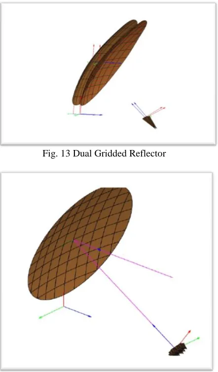
Fig. 13 Dual Gridded Reflector
[image:5.612.323.565.73.277.2]Fig. 14 Multi-Feed Parabolic Reflector
Fig.14 Offset Reflector
8. ADVANTAGES:
Creator-Decides creator based on objects association and interaction.
Expert-Assign those responsibilities to objects which has information to fulfill.
Low Coupling-Assign responsibilities so that coupling remains low.
High Cohesion-Easily understandable, code reuse.
Controller-Control sequence of activities, maintain the state of use case.
Polymorphism-Handling new variations will become easy.
Pure Fabrication-Responsibilities doesn’t represent any domain object.
Indirection-Introduces an intermediate unit to communicate between other units, so that other units are directly coupled.
Protection Variation-More structured design, flexibility.
9.APPLICATIONS
Single reflector with three Struts.
Dual reflector with blockage.
A single shaped reflector with circular polarization.
Dual gridded reflector.
Feed array.
Beam wave-guide.
Compact Antenna test range.
[image:5.612.75.296.288.665.2]224
10. CONCLUSION
We have successfully designed Parabolic Reflector Antenna using GRASP software. This software can be easily understandable by the users. We can also
design various antennas using the same software. It is available as Student-Version so that we can easily design any Antenna using this software.
REFERENCES
[1] SV, Devika. "Studies On Ka Band Otm Antennas For Effective Data Availability And Propagation Aspects In Current Satcom Applications And Services." (2018).
[2] Devika, S., Kotamraju, S., Sri Kavya, K., Sudheer Kumar, V., Suhas, K., Vinu, K., & Anudeep, B. (2016). A Circularly Polarized Ka-Band Antenna for Continuous Link Reception from GSAT-14. Indian Journal Of Science And Technology,9(38).
[3] Terada, M. A., & Stutzman, W. L. (1995). Computer-aided design of reflector antennas. Microwave Journal, 38(8), 64-71. [4] Maclean, T. S. M. (1986). Principles of