1290
Strengthening The Transient Stability Of A Power
Grid Coupled With Wind Turbine Using Thyristor
Controlled Series Capacitor
Nice Enyonam Akpeke, Christopher Maina Muriithi, Charles MwanikiAbstract: The increase diffusion and circulation of wind energy to the conventional power system due to rapid growth of energy demand has led to consideration of different wind turbine generator technologies. It has been discovered that, a power system experiences inevitable changes in its dynamic behavior when connected with Direct Drive Synchronous Generator (DDSG). In cases of an unexpected loss of a power source or a huge load, the frequency of the power system decreases, which eventually leads to difference in speeds between grid and the interconnected wind generator. It is therefore necessary to use FACTS devices among other methods to advance the dynamic behavior for a convectional power structure. This paper therefore focusses on enhancing PMSG-based system transient during 3ph fault situations. Reference is made to the Critical clearing time (CCT) as an evidence for evaluating the transient state for the system. Under the studies of 14-bus test system of IEEE and in PSAT, the critical clearing time for power system integrated to PMSG-based power turbine is improved with a Thyristor Controlled Series Capacitor (TCSC). One synchronous generator in the test network was replaced at random with the PMSG-based wind power source, intended to produce an equivalent power. Time domain (TD) simulations are performed considering two study cases. Simulation results show that, the CCT of the system with TCSC is longer than the CCT of system without TCSC, which is an indication of transient stability improvement.
Index Terms: Critical clearing time, permanent magnet synchronous generator, thyristor controlled series compensator, transient stability, wind power conversion system.
—————————— ——————————
1.
INTRODUCTION
LECTRICITY generation from wind is the fastest growing source of power due to its clear and numerous advantages such as economical and environmentally friendly [1]. The integration of any renewable energy source such as wind, to the power grid introduces all kinds of instability into the entire power structure. Transient stability, defined as the capability of the generators to remain in synchronism after a severe perturbations [2], [3], [4] is one major aspect of a power system that gets affected when large wind energy sources are associated with the conventional power system. This phenomenon can be linked to the fluctuations of the wind speed as a factor of the quantity of energy produced from the wind. Moreover, wind power generating units are asynchronous and therefore provide little inertia to the grid compared to the conventional generators [5]. The common wind turbine generator technologies considered in wind energy conversion are the Doubly Fed Induction Generator (DFIG), the Squirrel Cage Induction Generator (SCIG) and the Permanent Magnet Synchronous Generator (PMSG). SCIG is referred to as the first-generation wind turbine generator. It rapidly faded out of the system mainly as a result of lack of enough system reactive power support among other disadvantages. The DFIG which offers a better reactive power aid to the grid has become the most considered generator type in today‘s wind power generation owing to its long life, firm structure, reactive and active power regulation [6]. However, unlike the DFIG, the PMSG has a full-scale power converter and it is also a direct drive synchronous generator (gearless). It enables more reliable operation of wind turbines and also reduces maintenance [7]. These features made the PMSG more advantageous than the DFIG in wind power generation. Currently, most wind energy generator technologies employ turbines with PMSG [8], [9], [10]. Even though this wind turbine generator has a better reactive power capability, it is still not adequate as the principal precaution during transient conditions [11] and therefore need to be augmented with the dynamic reactive power capability of FACTS devices so as to strengthen the connected system‘s
transient state. Figure 1 depicts the various classification of wind turbine generators that exist. Impact analysis of a PMSG-based turbine on the transient stability of the electrical grid is carried out by Liu et al in [8]. The study considered a method of equal area criteria theory. Also, an active current control strategy which considered a perturbation estimation was proposed in [12] for enhancing the stability of the power structure connected with a PMSG-based turbine. Dimitrios et al in [13] conducted a simulation study by considering a TSSC to augment the effectiveness of a PMSG wind turbine. Zinat and Sheikh in [9] compared the transient stability enhancement between DFIG and PMSG. Following the simulation outcomes, the transient stability for the electrical grid coupled with induction wind generator improves with the inclusion of a PMSG. It was clearly stated that, a system with both PMSG and DFIG is more transiently stable than a system with one of the either generators. Reference [6] investigated the effects of series compensation for the transient enhancement of a DFIG-based wind power plant. After modelling 9-bus and 14-bus test systems and carrying out simulations in time domain, it was reported that the proposed series compensators can improve the transient state of a DFIG-based wind turbine power plant. In[14] , a study of the assessment of wind energy based on squirrel cage induction generator penetration effect on transient stability was provided. Different penetration levels were considered and the CCT analyzed. Patari et al in [10] conducted a transient stability improvement study by modifying the power converter control of a PMSG-based wind system. The simulation considered fault at different locations with different wind speeds. However, this paper is focused on transient state enhancement with reference to critical clearing time indicator.
2
I
MPLEMENTATIONO
FT
HES
YSTEMI
NP
SAT1291 implementing the two systems through the Simulink library.
The data used in implementing the system in PSAT is as found in [16].
2.1 The IEEE 14-bus Test System
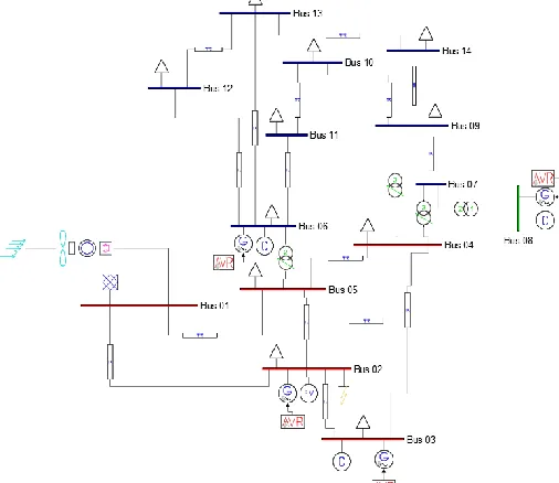
Implementation of this proposed testing power grid is done in PSAT 2.1.10 simulation software. The synchronous generator models, wind turbine model, model of the wind turbine power plant, constant loads together with the FACTS device are all inherent models adopted from MATLAB/Simulink library. The testing system is made of 5 generators and 8 constant loads. Out of the 5 generator buses, there is one reference (indicated at bus 1), one PV bus (at bus 2) with additional 3 synchronous condensers (at buses 3, 6 and 8) [1].Table.1 illustrates the summarizes the features of the IEEE-14 bus test network.
TABLE 1
FEATURES OF THE IEEE14-BUS TEST SYSTEM
Equipment Quantity
Buses 14
Generators 5
Transformers 4
Transmission lines 16
Loads 11
Three different voltage levels are chosen for the entire system equipment with a power rating of 100MVA. All the machines and other equipment in the system are rated at 69kv, 18kv or 13.8kv. Bus 1 is defined to be the reference bus (where the wind turbine is integrated). This is required for the purpose of specifying the essential voltage and real power for the generator available at that bus. This generator is the biggest generator in the system and it is connected to a 69kv bus and then to the rest of the system. The generator at bus 8 is linked to the rest of the system via a step-down transformer so as to cope with system voltage ratings for the whole network under consideration. The voltage ratings of all the buses are different; blue indicates a 13.8kv bus, green indicates an 18kv bus and red indicates 69kv bus. Figure 2 represents the IEEE 14-bus power system showing the PMSG integration.
Fig. 1. Modified IEEE 14-bus test power system coupled to PMSG
2.2 Permanent Magnet Synchronous Generator (PMSG) Model
The PMSG refers to a kind of synchronous generator. The rotor windings are replaced with a permanent magnet hence the name (PMSG). The constant magnet is either fixed on the surface of the rotor, embedded into the rotor surface or fitted inside the rotor. The generator‘s excitation field is introduced by the permanently embedded magnet in the rotor [17]. This arrangement has led to the elimination of the excitation losses that will take place in the rotor during starting of the generator. Consequently, the PMSG has better performance and higher efficiency as compared to other wind turbine generators since the rotor losses contribute to about 20-30% of the total generator losses [18]. In addition, the multi-pole layout of the PMSG allows better utilization of the power contained in the wind and it also allows gearless transmission of power. Even though the PMSG is a synchronous machine, its contribution to the grid inertia is still little compared to that of the conventional synchronous generators. This is because, it is interfaced to the grid through power electronic based converters [11]. Figure 2 illustrates a block diagram of the typical VS-wind power conversion structure based on PMSG. The System basically encompasses a wind turbine, a generator (PMSG), rectifier and an inverter.
Fig. 2. Block diagram of variable speed wind power conversion structure based on PMSG
The purpose of the power electronics based back to back power converter equipment involves controlling the generator rotor angle and also convert the electrical power available at the shaft of the generator into high quality power to be integrated into the power system. Total power produced by the wind turbine is mathematically represented in expression (1).
( ) (1)
(2)
Where:
P = turbine active power, = air density, = turbine blades swept area, = coefficient of power, = tip speed ratio, V = speed of wind, n = generator rotor speed. Since there is no gearbox, the aerodynamic torque (N/m) is equal to the mechanical torque[19] which is transferred to the generating unit. This is determined by a proportion of active turbine power (P) from the turbine to the speed (𝜔) of its rotor as shown in equation (3).
𝜔
(3)
1292 internally made of diode rectifiers and a DC-link. In any
reliable power system, it is significant for the system voltages to be maintained within permissible ranges in order to guarantee high quality services to customers [20]. The two coordinates (d-axis and q-axis rotating reference frames) helped in deriving the dynamic mathematical model for PMSG [18]. Equation (4) and (5) therefore defines the state equations, (6) defines the electrical equation whiles (7) defines the mechanical equation of the PMSG.
( ( ) )
(4)
( [( ) ] ) (5)
(6)
(( ) ) (7)
The d and q subscripts represent the real parameters converted to d reference frame and q reference frame. = the resistance of the stator (ohms). and = inductances of d-axis and q-d-axis (Henry), = leakage inductance, = permanent magnetic flux (Weber), and = d-axis and q-axis voltages, = the generator electro-magnetic speed (rad/s), p = pole pairs. Figure 3 and 4 illustrates the equivalent circuits of d and q-axis for the permanent magnet synchronous generator.
Fig. 3. The equivalent circuit of the d-axis
Fig. 4. The equivalent circuit of the q-axis
2.3 Thyristor Controlled series Compensator
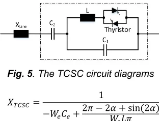
Generally, FACTS devices have a unique feature of rapidly controlling the system by their reactive power management. This characteristic is exploited in enhancing the transient state of the system. Thyristor controlled series compensator (TCSC) is an important flexible Alternating Current Transmission device used for increasing transmitted power as well as power system stability enhancement [2]. It is connected in series and hence acts serially in the power system. It consists of both series and shunt capacitors, and respectively. The shunt capacitor, is connected in parallel with an inductor, L. Figure 5 illustrates the TCSC circuit diagram. The over-all reactance of the device (represented by 𝑋 ) which is entirely
controlled by the thyristor is given by equation (8) with 𝛼 and 𝑊 representing its firing angle and the electrical angular frequency correspondingly.
Fig. 5. The TCSC circuit diagrams
𝑋
𝑊 𝛼 ( 𝛼)𝑊
(8)
The TCSC basically improves the transient state of the electric grid by adjusting the power line impedance. For proper placement of the TCSC to be achieved, the voltage stability index tool is employed in analyzing the voltage stability of the IEEE 14-bus testing network since FACTS devices are usually mounted in bus with low voltages [21], [22]. The use of voltage stability index creates awareness of the proximity of an electric network to voltage collapse or voltage instability [23]. It index also provides information about critical lines and buses (thus lines and buses with lowest voltage levels) hence needs more reactive power injection.
Fig. 6. Power system line model
Using figure 6 as an example of the power system line model (say from bus a to bus b), the fast voltage stability index (FVSI) of the power lines in the14-bus testing network is calculated using the expression in (9).
𝑋
(9)
1293 Fig. 7. A bar chat of the Fast Voltage Stability Index of the
various lines
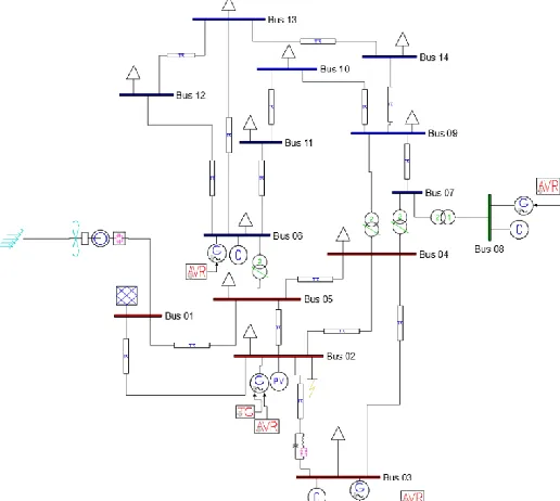
More reactive power is therefore injected through line ‗3‘ in order to boost the voltage level and hence upgrade the transient state of the whole power network. The altered IEEE-14 bus testing system coupled to both PMSG-based power plant (at bus 1) and TCSC (between bus 2 and 3) is shown in figure 8.
Fig. 8. Modified IEEE-14 bus power system integrated with PMSG-based wine turbine and TCSC
3 S
IMULATION RESULTS AND DISCUSSIONSimulations are carried out for two different cases during a 3ph to ground fault created in one of the buses. This is to compare the transient response of the two systems illustrated below:
i. Power system integrated with PMSG-based wind power plant
ii. Power system integrated with PMSG-based wind power plant and TCSC
The fault is created in bus 2 and the clearing time is varied until the system loses synchronism. Each of the synchronous generators in the network are monitored and the critical clearing time (CCT) in each case is noted with emphasis laid on the generator that is close to the position of the three phase fault.
3.1 Power System Coupled to PMSG-based Wind Turbine The aim of this simulation study is to find the improvement of the system transient state by analyzing the critical clearing
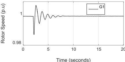
time. Figure 9-13 show the reactions of the synchronous generators in the system when only the PMSG-based wind power plant is integrated. In this case, the system has no TCSC. A plot of the speed deviation of all the synchronous generators (G1, G2, G3, and G4) at fault clearing time of 2.319 is shown in figure 9. It is observed that, even though the rotor speed of all the generators return to their original after the occurrence of the fault, generator 1 (G1) rotor speed has the highest magnitude. This is due to the closeness of the fault to generator 1. G1 is therefore the most affected synchronous generator in the system and hence all other parameters are plotted considering only generator 1 (G1).
Fig. 9. Plot of Rotor Speed of G1 with fault at 2s and cleared at 2.319s
Fig. 10. Plot of Rotor speed of G1 with fault at 2s and cleared at 2.319s
Fig. 11. Plot of Rotor speed of G1 with fault at 2s and cleared at 2.320s
0 0.2 0.4 0.6
1 3 5 7 9 11 13 15 17 19
F
ast
Voltag
e
S
tabili
ty
Inde
x
(
F
VSI
)
1294 Fig. 12. Plot of Rotor angle of G1 with fault at 2s and cleared
at 2.319s
Fig. 13. Plot of Rotor angle of G1 with fault at 2s and cleared at 2.220s
From the above swing curves of both rotor angle and speed deviation (rotor speed), it is deduced that, the synchronous generator G1 (at bus 2) remains stable if the fault is cleared before or at exactly 0.319s following the occurrence of the fault. This is shown in figure 10 and 12. On the other hand, a delay in the fault clearing time to 0.320s following the occurrence of the fault causes the system to lose its synchronism as shown in the curves of figure 11 and 13. Consequently, the critical clearing time of the network coupled to a PMSG-based wind power source as far as the position of the fault is concerned is 0.319s.
3.2 Power Network Coupled with PMSG-based Wind Power Source and TCSC
For this case, the IEEE-14 bus testing network in the first case is further modified by integrating a TCSC in line ‗3‘ (between bus 2 and 3) in order to increase the critical clearing time as stated in case I. the transient response of generator one is monitored just as in case I and the fault clearing time noted. As seen from figure 14 - 17, the synchronous generator 1 (G1) remains stable when the fault is cleared not beyond 0.540s following the fault occurrence. Stability of the electrical network can be observed from figure 14 and 16. On the contrary, a delay in the clearing time of fault to 0.541s prevents the grid from becoming transiently stable (figure 15 and 17). Thus, 0.540s is the CCT following a fault created at 2s of the power grid integrated with TCSC which is greater than 0.319 in the first case.
Fig. 14. Plot of Rotor speed of G1 with fault at 2s and cleared at 2.540s
Fig. 15. Plot of Rotor speed of G1 with fault at 2s and cleared at 2.541s
Fig. 16. Plot of Rotor angle of G1 with fault at 2s and cleared at 2.540s
Fig. 17. Rotor angle of G1 with fault at 2s and cleared at 2.541s
It is therefore stated that, the critical clearing time for the network is increased by 0.221s with the integration of TCSC. This value is obtained by subtracting the CCT of case 1 from that of case 2 and it is calculated as follows:
(10)
1295 (12)
(13)
Thus, it takes a longer time for the system with TCSC to lose synchronism and become transiently unstable, hence TCSC has been utilized in improve the transient state of the power grid by increasing the CCT of the system in which it is connected.
4
CONCLUSION
This paper studied transient stability improvement of an electrical power network which has high penetration of a wind power based on PMSG turbine using TCSC. Critical clearing time (CCT) index is employed as an indication for the analysis. For the purpose of this study, a DFIG wind turbine in an existing IEEE-14 bus system model in PSAT was replaced by a PMSG-based wind power source. The system was further modified by integrating a TCSC and the critical clearing time noted by monitoring the angle of the rotor and its speed respectively. The study considered a three phase fault created at 2s at bus 2. The parameters of the study were analyzed for the synchronous generator at bus 2. It was proved from the results that, critical clearing time of the network increased with the integration of a TCSC in the system that already had a PMSG-based wind turbine. The results obtained show that TCSC could be utilized to enhance the system transient stability.
ACKNOWLEDGMENT
The authors wish to appreciate the Pan African University, Institute for Basic Sciences, Technology and Innovation (PAUISTI) for their financial support.
REFERENCES
[1] M. K. Nigam, S. Singh, and C. Francis, ―Effects on Power System Stability due to Integration of Distributed Generation,‖ Journal of Science and Engineering Education, vol. 2, pp. 56–60, 2017. [2] A. devi Patel, ―A review on FACTS Devices for the
Improvement of Transient Stability,‖ Global Journal of Engineering Science and Resources, vol. 2, no. 12, pp. 85–89, 2015.
[3] N. W. Miller, M. Shao, S. Pajic, and R. D. Aquila, ―Western Wind and Solar Integration Study Phase 3 – Frequency Response and Transient Stability,‖ 2014. [4] S. Xia, Z. Qian, S. T. Hussain, H. Baodi, and Z.
Weiwei, ―Impacts of Integration of Wind Farms on Power System Transient Stability,‖ Applies Sciences, vol. 8, no. 8, p. 1289, 2018.
[5] M. Pertl, T. Weckesser, M. Rezkalla, and M. Marinelli, ―Transient Stability Improvement : A Review and Comparison of Conventional and Renewable based Techniques for Preventive and Emergency Control,‖ Electrical Engineering, vol. 10. pp. 1–20, 2017.
[6] H. A. Abu and A. M. Hasan, ―Comparison Among Series Compensators for Transient Stability Enhancement of Doubly Fed Induction Generator Based Variable Speed Wind Turbines,‖ The Institute of Engineering and Technology, vol. 10, pp. 1–11, 2015. [7] P. Badoni and S. B. Prakash, ―Modeling and Simulation
of 2 MW PMSG Wind Energy Conversion Systems,‖
IOSR Journal of Electrical and Electronic Engineering, vol. 9, no. 4, pp. 53–58, 2014.
[8] Z. Liu, C. Liu, G. Li, Y. Liu, and Y. Liu, ―Impact Study of PMSG-Based Wind Power Penetration on Power System Transient Stability Using EEAC Theory,‖ Energies, vol. 12, no. 8, pp. 13419–13441, 2015. [9] Z. Tasneem and M. R. Sheikh, ―Transient Stability
Improvement of a Fixed Speed Wind Driven Power System using Permanent Magnet Synchronous Generator,‖ in International Conference on Mechanaical Engineering, 2014, vol. 90, pp. 698–703. [10] N. Patari, D. Chatterjee, and T. Bhattacharya,
―Transient Stability Improvement by Pre-fault and Post-fault Modifications in Wind Power Plant Control.‖ [11] M. Nazmul, I. Sarkar, L. G. Meegahapola, and M.
Datta, ―Reactive Power Management in Renewable Rich Power Grids : A Review of Grid-Codes , Renewable Generators , Support Devices , Control Strategies and Optimization Algorithms,‖ IEEE Access, vol. 6, no. 10, pp. 41458–41489, 2018.
[12] P. Shen, L. Guan, Z. Huang, L. Wu, and Z. Jiang, ―Active-Current Control of Large-Scale Wind Turbines for Power System Transient Stability Improvement,‖ Energies, vol. 11, no. 8, pp. 1–15, 2018.
[13] D. Kalpaktsoglou, S. Pouros, and K. Kleidis, ―Improving the Efficiency of a Wind Turbine using Thyristor Switched Series Capacitors- A Simulation Study,‖ WSEAS Transactions on Power Systems, vol. 14, pp. 33–38, 2019.
[14] M. Amroune and T. Bouktir, ―Power System Transient Stability Analysis with High Wind Power Penetration,‖ International Electrical Engineering Journal, vol. 4, no. 1, pp. 907–913, 2013.
[15] L. Zhang, D. Jiang, and Z. Li, ―Transient Stability Analysis of Power System Using Improved Least Square Method,‖ in 3rd Internation Conference on Electric and Electronics, 2013, no. 1951–6851, pp. 337–340.
[16] T. A. Lipo, Energy Function Analysis for Power System Stability. London: Kluwers Academic Publishers, 1989. [17] R. K. Tiwari and K. K. Sharma, ―Simulation and
Modeling of Wind Turbine using PMSG,‖ International Journal of Recent Research and Review, vol. 7, no. 2, pp. 46–50, 2014.
[18] A. Gustavo, A. Rolan, A. Luna, and G. Vazquez, ―Modeling of a Variable Speed Wind Turbine with a Permanent Magnet Synchronous Generator,‖ in IEEE International symposium on INdustrial Electronics, 2009, no. 9, pp. 734–739.
[19] H. M. Aslam and T. Abu, ―Modeling and Study of a Standalone PMSG Wind Generation System Using MATLAB / SIMULINK,‖ University Journal of Electrical and Electronic Engineering, vol. 2, no. 7, pp. 270–277, 2014.
[20] A. Khattara, M. Becherif, M. Y. Ayad, and A. Aboubou, ―The Choice of DFIG Wind Turbine Location According to its Line Fault Ride Through (LFRT) Capability,‖ Revue des Energies Renouvelables SIENR, pp. 263– 267, 2014.
1296 998–1003, 2016.
[22] S. I. Adekunle, ―A New Voltage Stability Index for Oredicting Voltage Collapse in Electrial Power System Networks,‖ Covenant University, 2017.