Ultra Wide Bandwidth High Gain Vivaldi Antenna for Wireless
Communications
Dalia M. Elsheakh1, *, Nermeen A. Eltresy2, and Esmat A. Abdallah1
Abstract—In this paper an ultrawide bandwidth double-layered Vivaldi antenna (DLVA) integrated
in Radome housing is proposed. First the conventional Vivaldi antenna is designed with bandwidth extended from 1.8 to 6 GHz at VSWR (3 : 1). Then for wider bandwidth, two slots are etched in the antenna ground plane to extend the antenna bandwidth from 1.7 to 9 GHz. For more improvement in antenna bandwidth, circular slots as electromagnetic band-gap structure (EBG) are etched to further extend the antenna bandwidth from 1.45 to 10 GHz. For gain enhancement double layers of Vivaldi antenna ground plane are designed with the same feeding line to reach 29 dBi peak. High frequency structure simulator (HFSS) ANSYS is used to design and simulate all the design steps. The proposed antenna is fabricated and measured. Finally, DLVA is integrated inside the Radome to improve the antenna gain and protect the proposed antenna from environmental factors. The antenna is fabricated and tested, and a good agreement between simulated and measured results is found.
1. INTRODUCTION
Recently, radar, microwave imaging, remote sensing, and ultra-wideband (UWB) communication systems use ultra-wideband antennas, which have compact size and high gain. Tapered slot antennas (TSA) with UWB and high gain are a suitable choice, which have advantages of compact size, wide impedance bandwidth, and high gain. Granted by the U.S. Federal Communications Commission (FCC), the frequency bandwidth from 3.1 to 10.6 GHz is allocated for UWB applications which is 7.5 GHz wide [1–3]. Design of a UWB dual-polarized array of differentially fed tapered slot antenna elements is presented in [4–6]. It is used for astronomical applications. Vivaldi antenna is a kind of tapered slot antenna with broadband, high gain and light weight. The structure of a Vivaldi antenna is composed of a taper slot, which is considered as a two-dimensional exponential horn. This tapered slot is mounted on a dielectric substrate which is mounted on ground plane. Vivaldi antenna can be designed in antipodal shape, which is called antipodal Vivaldi antenna. This antipodal Vivaldi antenna has the advantage of wider bandwidth than regular Vivaldi antenna [7–10]. Dispersion behaviour of specific Vivaldi antennas investigated in both frequency and time domains is introduced in [11]. The Vivaldi antenna can be used as a sensor for a microwave breast cancer detection system [12]. A UWB high gain compact Vivaldi antenna with endfire radiation pattern is also presented for radar and microwave imaging applications [13, 14]. Vivaldi antenna is linearly polarized. It can be designed for circular polarization as in [15]. Also Vivaldi antenna can be used to build array. Vivaldi antenna array is investigated in [16] which has compact size because it consists of eight Vivaldi antenna elements connected sequentially and folded into a hollow cylinder. Also two different types of Vivaldi antenna arrays are designed in [7], which are for UWB through wall applications. The first is a 16×1 antipodal Vivaldi antenna which covers 8–12 GHz, and the second is an 8×1 tapered slot antenna for 2–4 GHz frequency band.
Received 5 June 2017, Accepted 3 July 2017, Scheduled 2 August 2017
* Corresponding author: Dalia Mohammed Nasha Elsheakh (daliaelsheakh@eri.sci.eg).
In this paper, a UWB double-layered Vivaldi antenna inside radome is designed for ultrawide bandwidth and high gain. The antenna structure with design and the evolution of the proposed antenna are presented in Section 2. In Section 3, the simulation and measurement of the proposed antenna are discussed in terms of the antenna impedance, reflection coefficient, surface current distribution, group delay, radiation efficiency and antenna gain. The fabricated antennas are evaluated based on the measurements of reflection coefficient. Finally, Section 4 presents the conclusion of the proposed work.
2. ANTENNA DESIGN
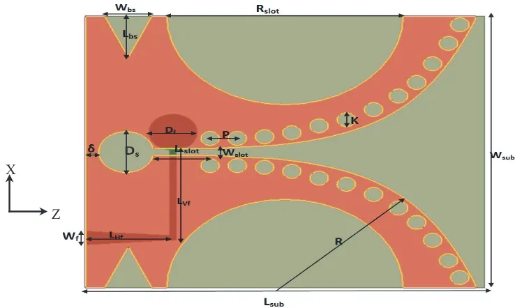
The Vivaldi antenna is printed on a dielectric substrate of FR-4 with dielectric constant εr = 4.5 and tan δ = 0.02. The substrate has dimensions (Lsub×Wsub), and thickness of substrate is 1.6 mm. The proposed Vivaldi antenna is shown in Fig. 1. All simulations are carried out using the EM commercial simulator HFSS version 14.0, which is based on the finite-element numerical method. The first design is a conventional Vivaldi, fed using a line which excites a circular space via a microstrip line and terminated with a sector-shaped area as shown in Fig. 1(a). The ground plane and feeding network dimensions are shown in Table 1. Exponential curvature can be changed according to the exponential rate (R).
(a) (b)
Figure 1. The top view of Vivaldi antenna, (a) conventional Vivaldi, (b) modified Vivaldi.
Z X
The shape of the curvature influences the beginning of the taper and the wide end of the taper. On both places, a reflection of the traveling wave is likely to occur. The exponential pattern is given by
R = ±0.018e0.27z to improve the impedance bandwidth. Then the symmetrical slots R
slot are etched
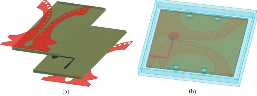
to increase the antenna bandwidth as shown in Fig. 1(b). The modified version from the first one is obtained by slotting the two arms of the Vivaldi antenna. Then circular slots as EBG structure are etched at the edge in the two exponential shapes of Vivaldi antenna ground plane. Also, a triangular slot is etched to add more reduction in size and to improve the bandwidth of the Vivaldi antenna. The proposed antenna design is shown in Fig. 2. This design is used to investigate a dual-layered Vivaldi antenna as shown in Fig. 3(a). DLVA consists of two layers from the the dielectric sheet, and the feeding line is sandwiched between them, and the two layers of metal Vivaldi are mounted on the dielectric sheet (one at the top and the other at the bottom). The DLVA achieves improvement in both antenna impedance matching and gain all over the band. The 3-D structure of the DLVA is shown in Fig. 3(a). Fig. 3(b) shows the DLVA inside a radome. The complete optimized dimensions of the proposed antenna with the dimensions in Figure 2 are shown in Table 1.
(a) (b)
Figure 3. (a) 3-D structure of dual layered Vivaldi antenna and (b) antenna with radome.
Table 1. Dimensions of the proposed antenna (dimensions in mm).
Lsub Wsub LHf LLf Wf K
50 48 16 6.2 2.6 2
Rslot Lslot Ds Wbs Lbs Wslot
26 8 7 6.2 7 1.2
Wf Df P Lvf δ R
2.5 6.5 4 11 1.8 ±0.018e0.27z
3. SIMULATION AND MEASURED RESULTS
1 2 3 4 5 6 7 8 9 10
-40 -30 -20 -10 0
Reflection Coefficient (dB
)
Frequency (GHz)
Conventional Vivaldi Modified Vivaldi
Modified Vivaldi with EBG Dual Vivaldi
Dual Vivaldi with radom
Figure 4. |S11| versus frequency for the design steps of the proposed antennas.
1 2 3 4 5 6 7 8 9 10
0 50 100 150 200
Real impedan
c
e
(ohm
)
Frequency (GHz)
Single Layer Dual Layer Dual with Radome
1 2 3 4 5 6 7 8 9 10
-160 -120 -80 -40 0 40 80 120 160
Im
a
g
nary impedan
c
e
(
O
h
m
)
Frequency (GHz)
Single Layer Dual Layer Dual with Radome
(a) (b)
Figure 5. Vivaldi antenna impedances for (a) real part and (b) imaginary part.
average. Radiation patterns at optimized DLVA antenna dimensions are measured by using homemade far-field anechoic chamber at different frequencies.
1 2 3 4 5 6 7 8 9 10 -5 0 5 10 15 20 25 Gain (dBi ) Frequency (GHz) Single Vivaldi Dual Vivaldi
Dual Vivaldi with Radome
Figure 6. Vivaldi antenna gain variation versus frequency of the proposed antenna.
Table 2. Measured and simulated radiation patterns of DLVA in bothXY and XZ planes at different
frequencies. 1.8, 2.4, 3.5, 5.2, 8 and 10 GHz.
Fre. XZ XY Fre. XZ XY
1. 8 -4 0
-3 0 -2 0 -1 0 0 0 30 60 90 120 150 180 210 240 270 300 330 -40 -30 -20 -10 0 -40 -30 -20 -10
00 30
60 90 120 150 180 210 240 270 300 330 -40 -30 -20 -10 0 2. 4
3. 5 5. 2
8 10 -4 0
(a) (b) (c)
Figure 7. Photo of the DLVA, (a) the top view, (b) the bottom view of the first layer, (c) the bottom
view of the second layer.
1 2 3 4 5 6 7 8 9 10
-40 -30 -20 -10 0
|S 11
| (dB)
Without EBG Simulated Measured
1 2 3 4 5 6 7 8 9 10
-40 -30 -20 -10 0
|S 11
| (d
B
)
W ith E B G S im ulated M easu re d
Frequency (GHz) Frequency (GHz)
(a) (b)
Figure 8. Reflection coefficient versus frequency for the proposed Vivaldi antennas, (a) without slot
and (b) with EBG.
1 2 3 4 5 6 7 8 9 10
0.00 0.25 0.50 0.75 1.00 1.25 1.50 1.75 2.00 2.25 2.50
Nano
Second
Frequency (GHz)
Group delay
Measured Simulated
4. CONCLUSION
A conventional UWB Vivaldi antenna is designed. Then a modified Vivaldi antenna is designed by inserting two exponential shapes in the ground plane. Finally, circular slots at the edge of the antenna ground plane are etched to get modified Vivaldi EBG to achieve wider bandwidth than the conventional Vivaldi antenna. After that, a Vivaldi antenna with more circular slots at the edges of the antenna arms and triangular slot have been designed to get modified Vivaldi EBG with a wider bandwidth than the conventional Vivaldi antenna. Also a dual-layered Vivaldi antenna is introduced. Study of the behavior of the DLVA inside the radome is performed, which indicates that the DLVA inside the radome has better performance for both antenna impedance and gain all over the operating bandwidth. The antenna is fabricated, and the performance is measured.
REFERENCES
1. Bharti, P. K., “High gain Vivaldi antenna for radar and microwave imaging applications,”
International Journal of Signal Processing Systems, Vol. 3, No. 1, 35–39, 2015.
2. Hood, A. Z., T. Karacolak, and E. Topsakal, “A small antipodal Vivaldi antenna for ultrawide-band applications,” IEEE Antennas and Wireless Propagation Letters, Vol. 7, 656–660, 2008.
3. Ma, T. G. and S. K. Jeng, “A printed dipole antenna with tapered slot feed for ultrawide-band applications,”IEEE Transactions on Antennas and Propagation, Vol. 53, No. 11, 3833–3836, 2005. 4. Acedo, E., E. Garcia, V. Gonz´alez-Posadas, J. L. V´azquezRoy, R. Maaskant, and D. Segovia, “Study and design of a differentially-fed tapered slot antenna array,”IEEE Transactions on Antennas and
Propagation, Vol. 58, No. 1, 68–78, 2010.
5. Yang, Y., Y. Wang, and A. E. Fathy, “Design of compact Vivaldi antenna arrays for UWB see through wall applications,” Progress In Electromagnetics Research, Vol. 82, 401–418, 2008.
6. Alhawari, A. R., A. I. Smail, M. A. Mahdi, and R. S. A. R. Abdullah, “Antipodal Vivaldi antenna performance booster exploiting snug-in negative index metamaterial,”Progress In Electromagnetics
Research, Vol. 27, 265–279, 2012.
7. Bayat, A. and R. Mirzakhani, “A parametric study and design of the balanced antipodal Vivaldi antenna (BAVA),” PIERS Proceedings, 778–782, Moscow, Russia, August 19–23, 2012.
8. Agahi, M. H. H., H. L. Abiri, and F. Mohajeri, “Investigation of a new idea for antipodal Vivaldi antenna design,” International Journal of Computer and Electrical Engineering, Vol. 3, No. 2, 1793–8163, 2011.
9. Narbudowicz A., M. John, and X. Bao, “Vivaldi array for generation of UWB circular polarization,”
IEE Anten. and Propagat. Society International Symposium (APSURSI), Chicago, IL, USA, 2012.
10. Bourqui, J., M. Okoniewski, and E. C. Fear, “Balanced antipodal Vivaldi antenna with dielectric director for near-field microwave imaging,” IEEE Transactions on Antennas and Propagation, Vol. 58, No. 7, 2318–2326, 2010.
11. Mehdipour, A., K. Mohammadpour-Aghdam, and R. Faraji-Dana, “Complete dispersion analysis of Vivaldi antenna for ultra wideband applications.”Progress In Electromagnetics Research, Vol. 77, 85–96, 2007.
12. Deng, C., W. Chen, Z. Zhang, L. Yue, and Z. Feng, “Generation of OAM radio waves using circular Vivaldi antenna array,” International Journal of Antennas and Propagation, Vol. 2013, 1–8, 2013. 13. Bitchikh, M. and F. Ghanem, “A four bandwidth-resolution UWB antipodal Vivaldi antenna,”
Progress In Electromagnetics Research M, Vol. 53, 121–129, 2017.
14. Etesami, F., S. Khorshidi, S. Shahcheraghi, and A. Yahaghi, “Improvement of radiation characteristics of balanced antipodal Vivaldi antenna using transformation optics,” Progress In
Electromagnetics Research M, Vol. 56, 189–196, 2017.
15. Liu, C., A. Yan, C. Yu, and T. Xu, “Improvement on a 2×2 elements high-gain circularly polarized antenna array,”International Journal of Antennas and Propagation, Vol. 2015, 1–8, 2015.