Torque and Ripple Improving of a SR Motor Using Robust Particle
Swarm Optimization of Drive Current and Dimension
Abbas Ketabi, Ata Yadghar*, and Mohammad J. Navardi
Abstract—In this paper, the robust optimization shape and drive of switched reluctance motors (SRMs) are discussed using robust particle swarm optimization (RPSO). The shape optimum goal of the algorithm was found for maximum torque value and minimum torque ripple, following changing the geometric parameters. The drive optimum aim of the algorithm was found minimum torque ripple, following changing the current profiles. The optimization process was carried out using a combination of RPSO and Finite Element Method (FEM). Fitness value was calculated by FEM analysis using COMSOL 4.2, and the RPSO was realized by MATLAB 2011. The proposed method has been applied to two case studies and also compared with seeker optimization algorithm. The results show that the optimized SRM using RPSO has higher torque value, lower torque ripple and higher robustness, indicating the validity of this methodology for SRM design and implementation.
1. INTRODUCTION
Switched reluctance motors (SRMs) are widely used in different applications such as new generation of transportation. Simple and strong structure, high efficiency, low weight and small size due to the absence of rotor windings, variable speed operations, high torque to inertia ratio, reliability, relatively low manufacturing costs and fault permissibility of SRM are reasons for choosing a SRM in industry especially in electrical vehicles [1]. High starting torque for initial acceleration, high average torque, and high efficiency to save battery for a longer operating time are the main factors to design such a practical motor [2]. Furthermore, these features make SRM a viable alternative to other commonly used motors such as AC, BLDC, PM Synchronous or universal motors for numerous applications. The most important disadvantage of SRM is its high torque ripple in comparison with other electrical motors. It causes acoustic noises and mechanical vibration. Applying discrete current to sequenced phase is the main reason of torque pulsation. There are two known methods for torque ripple minimization: I) driver optimization, II) geometry change [2]. The geometry of a SRM consists in different parameters that affect the features of the motor. Various researches on geometries and drive design of SRM and generators have been successfully investigated in the past. In [1], a FEM analysis showed that the effects of phase current chopping of a sample 8/6 SRM could reduce the core loss about 50%. Nevertheless, no exact explanation about the frequency and amplitude was provided. A torque sharing function theory was introduced in [2]. In [3], the phase current profile optimized and compared to constant phase current profile. In [4], the changing of EMF was used for modifying torque, where the phase current overlapping was integrated to reduce torque ripple where the motor simulated with mathematical equation and FEM analysis was ignored. In [5], a PI filter was employed to create novel phase voltages, to obtain a ripple free torque by a PWM digital signal processor device. Ref. [6] compared a PWM voltage generator once without commutation and once again with an optimized phase commutation angle and concluded that the commutation angle method revealed the efficiency. Using PWM direct torque observation during
Received 22 November 2015, Accepted 29 December 2015, Scheduled 12 January 2016
the movement of the rotor is a method proposed in [7]. Unfortunately, direct control of torque is not confirmable as the best method of motor features optimization. In [8], by NSGA-II optimization method decided the constants in PI-Filter of the PWM and also the values of cut-off and cut-on angles when commuted between phases as in [9] which suggested two values for the end of raising and the beginning of falling current in each phase. In [10], a new method of torque sharing function was introduced. Instead of bipolar excitation of a SRM, in [11] a single pole excitation was proposed, which can reduce the torque ripple but increase the price of product. In [12], a fitness function by weighting two objective functions (torque ripple and copper loss) was proposed but without introducing the optimization method. In [13], besides the speed stability of a BLDC motor that worked similarly to a SRM, it was claimed that the designed drive was able to correct the power factor by the advantages of using isolated-zeta converter. In such a context, many researches have successfully addressed the drive optimization problem [14–17]. Seeker Optimization Algorithm (SOA) has been used in SRM geometric optimization [18]. The most efficient aim of the algorithm was found for maximum torque value at a minimum mass of the entire construction, following changing the geometric parameters. Normal back-EMF method was replaced by an integral variable structure module in [19, 20] and operated in three options, two phase conduction mode, low speed commutation mode, high speed commutation mode for different cases of motor performance. In [21, 22] besides the consideration of core saturation of the SRM, a selection method of reference current points from outgoing to incoming phase is introduced to optimize the torque ripple. DE optimization has been applied to design a low torque ripple and copper loss and a high average torque motor by modifying the angle and dimension of stator and rotor poles [23, 24].
Until recently, the robust design issues in the optimal geometry SRM design have been barely addressed [25]. From a mathematical point of view, SRM design problem can be modeled as an optimization problem and be solved, but in the implementation, manufacturing tolerances of motor parameters are challenge. Therefore, optimization methods are required that can deal with unavoidable uncertainties (noise factors) in the industrial manufacturing process, such as material characteristics and manufacturing precision [26]. The practice of optimization that accounts for uncertainties and noise is often referred to as robust optimization [27–30]. In this paper, a new method of optimization is employed to find a practical and ready to manufacture design of drive and geometry of SRM. The base algorithm of optimization is originated from Particle Swarm Optimization (PSO) method integrated with a neighborhood looking-up lemma to provide the robustness of the design. This feature of the design permits a range of parameters, to prevent the unwelcome errors effects on design objective functions. The aim of our investigation is to reach maximum torque value at a minimum torque ripple. To get the optimum shape and drive performance of the motor, a combination of FEM and Robust PSO (RPSO) is organized. The fitness value of the objective functions is estimated by COMSOL 4.2, and the optimization individuals are decided using MATLAB by the applied RPSO algorithm. The proposed method has been applied to a case study, and it has also been compared with Seeker Optimization Algorithm [18].
This paper is organized as follows. Section 2 describes the principle of SRM and drive performance. Section 3 proposes a RPSO method for designing a current profile of drive and also the geometry of rotor and stator. Section 4 discusses the results, and finally the conclusion is drawn in Section 5.
2. PRINCIPLES OF SWITCHED RELUCTANCE DESIGN
2.1. SRM Geometry Design Characteristics
SRM have salient poles that the windings are concentrated on stator poles. The phase induction varies, since the related air gap between rotor and stator poles changes in every other period [20]. The procedure of rotation energizes the stator phase and pulls the rotor pole towards the related stator pole. There are different types of winding excitation, but in our case of study 6/4 SRM no more than two phases are conducted. During the excitation phase voltage equation is derived as:
v=R·i+∂λ
∂t (1)
ripple and fewer poles help reducing the loss of switching. In this paper a 6/4 SRM has been chosen due to its modified trade-off between loss and torque ripple. Thanks to previous researches, a 6/4 SRM provides a wider range of constant power and torque production than its low switching loss [18]. The co-energy of a SRM is calculated as:
Wf = 1
2L(θ)·i
2 (2)
where L is the inductance of the air gap field changed through the changing of θ, and i is the phase current which is variable in this paper due to the modification of the phase current profile. Then the electromagnetic torque is given by partial derivative of the co energy with respect to theta.
Tf =
∂Wf
∂θ =
1 2i
2·∂L(θ)
∂θ (3)
The induction varies during the movement of rotor as:
L(θ) = N
2
R(θ) (4)
where N is the number of turns per phase and Rthe reluctance between rotor and stator, which is a function of θ.
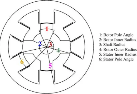
As well known, the torque ripple and torque output are sensitive to geometry variables of stator and rotor, and their selection is a vital part of SRM design process [18]. Therefore, for the shape optimization, six design parameters, shaft radius, rotor pole angle, rotor inner radius, rotor outer radius, stator inner radius and stator pole angle, as shown in Fig. 1, are selected as design variables. Optimization process is programmed to maximize the average torque and to minimize the torque ripple by defining the following equations:
Tave = 1
Θ
Θ
0
T(θ)dθ (5)
T orque Ripple = Tmax−Tmin
Tave (6)
whereT(θ) is electromagnetic torque at the rotor position θ, Θ the associated electrical period equal to ninety degrees, andTmaxandTmin are maximum and minimum ofT(θ) over one period Θ, respectively.
The objective function, which will satisfy both conditions of maximum average torque and minimum ripple torque, is a fitness function defined as in Eq. (7).
f itness f unction= T orque Ripple
Tave (7)
In this article, the electromagnetic torque per meter of axial thickness has been computed by a two-dimensional finite element method (2-D FEM). Since the torque is linearly proportional to the motor axial length, the calculated torque per meter needs to be multiplied by the motor axial length. COMSOL 4.2 meshes the rotor and stator poles and the space between them in triangular form and then solves stationary Maxwell’s equations by a linear or nonlinear solver automatically. The software calculates the co-energy and torque through air gaps in every 2-degree rotation of the rotor. All the results are saved in an array in MATLAB 2011. For SRM, there is an optimum angle called “firing angle” between two stator poles, which the controller should switch between windings and turn on the next phase for building a rotating magnetic field [18]. The firing angle (FA) equation is as following.
This research is highly concerned about the torque average and torque ripple of the motor, so in fitness function the mass of the motor has been ignored.
2.2. SRM Drive Characteristics
Figure 1. Optimization variables.
provides independent control of individual phases. Providing accurate and pre-determined current requires 3 current source inverters in the case of utilizing a 6/4 SRM. The drive is commanded by a pre-determined current curve that is optimized. The value of phase current can be varied in every 2-degree rotation during the rotor movement. Fig. 2 shows a microprocessor based drive, used to ignite the transistor in each phase.
Figure 2. SRM typical drive.
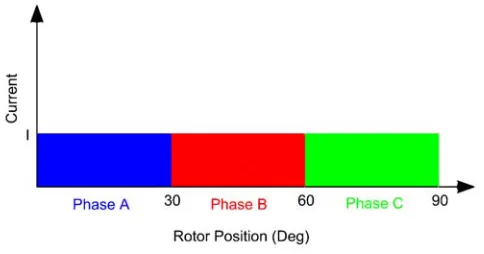
In this case, 3 of these drives have been employed. The duty cycle of the buck DC-DC convertor determines the value of falling current. In [18], the DC current source set to the maximum current needed for phase excitation. There are several ways to minimize the torque ripple using drive performance, such as 1) phase overlapping and 2) hysteresis band setting [14]. But a less investigated item is phase current profiling. Fig. 3 shows the ideal current commutation and profile for a three-phase motor. Each phase is applied to the related current by 30 degrees, and the incoming phase rises right after the outgoing phase is turned off. The objective of obtaining a new current phase profile is to reach a flat and free torque ripple [9]. A fast and also cheap device is needed to change the dc current source by every 2 degrees of rotor rotation. Therefore, for the drive optimization, 15 design parameters, phase current in every 2 degrees over one 30 degrees, are selected as design variables. It has pre-programmed by the optimization output and influenced by the position of rotor and its polar distance to aligned and unaligned positions.
The objective function for the drive optimization problem, which will satisfy both conditions of maximum average torque and minimum ripple torque, is a fitness function defined as in Eq. (7).
Figure 3. Ideal phase communication of SRM.
produced without the use of compensator lead networks. Transistor fails because overcurrent coming from the source can be prevented. Also by a pre-design solution, the saturation of the motor excited iron can be avoided. This research has tried to achieve an appropriate profile of torque with pre-determined fall of current in special position of the rotor during the excitation of each phase. The overlapping of incoming and outgoing phases has been neglected according to the ideal current commutation.
2.3. Robust Design
From a mathematical point of view, SRM design problem can be modeled as an optimization problem and be solved, but in the implementation, manufacturing tolerances of motor parameters and accuracy tolerance of motor drive current are design challenges. Hence, for real-world scenarios, optimization methods are needed, which can deal with these uncertainties, and solutions ought to be found, which are not only optimal in the theoretical sense, but also practical in real life. The practice of optimization that accounts for uncertainties and noise is often referred to as robust optimization. Here “robust” is intended in the sense that the optimum found by the algorithm is not too sensitive with respect to small changes in the parameters. In this article, the robust optimum with respect to manufacturing tolerances and drive current tolerance is obtained by the application of the RPSO algorithm.
3. ROBUST PARTICLE SWARM OPTIMIZATION
3.1. Particle Swarm Optimization
In past several years, PSO has been successfully applied in many researches to find an optimised solution for a problem. Many researchers believe that results are obtained faster and more accurate than other methods [26]. PSO is a population based stochastic optimization technique [26]. Such as Genetic Algorithms, PSO stocks many similar results with evolutionary computation techniques. Like many evolutionary algorithms, the system begins with an initial stochastic population and continues with optimization of the generations. PSO does not have mutation and crossover unlike GA. There are potential solution individuals in PSO, which fly all over the problem by means of defined vector. The particles move through a defining space by the guidance of best solutions called “PBEST”. Another best solution is obtained by the competition between neighborhoods of the best fitness value individuals called “GBEST”. According to the position of the bests, PSO gives a variable velocity in each step to the solutions. Few parameters should be set before solving a problem. It is one of the reasons that PSO is applied to many researches and becomes more attractive in recent years.
3.2. RPSO
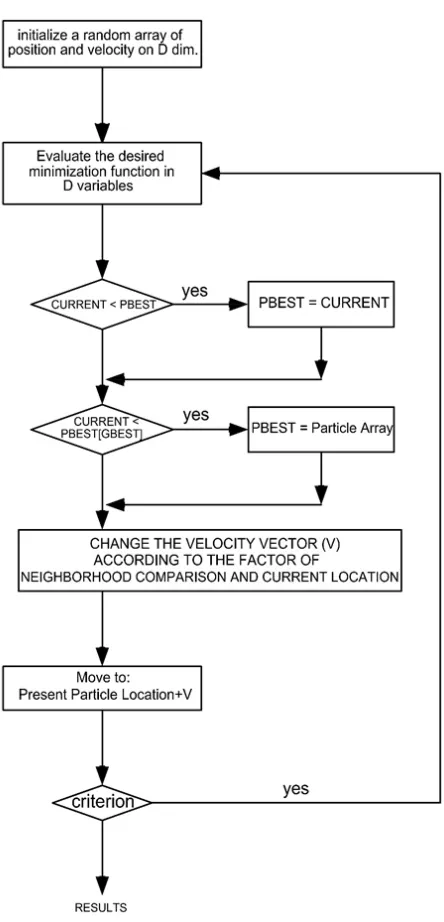
Figure 4. RPSO algorithm.
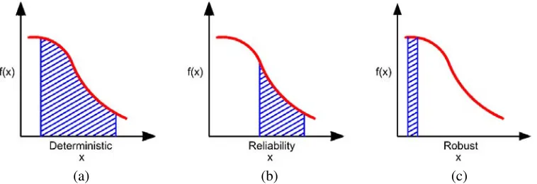
I) Deterministic: Providing a range of Pareto front and letting the client responsible for choosing a solution.
II) Reliability: if deterministic solutions limited to a range of smoother Pareto front the client can choose its desired solution from a wider range with low tolerance of objectives.
III) Robust: There are several situations, in which a scientist decides to solve the optimization problem by robust optimization. First the inappropriate conditions of environment and operational circumstances. Second, the parameters might change after the motor operation or during the procedure of manufacturing. Third, the system itself may produce noisy outputs. So seeking for a smooth and flat area in a Pareto curve is the research goal, called robust optimization.
(a) (b) (c)
Figure 5. Comparison among reliable, deterministic and robust selections of Pareto front candidates.
appropriate areas can be seen for robust optimization [29]. In general, the robust optimization main equation can be defined as follows:
fexp=
+∞
−∞
f(x+δ)·pdf(δ)dδ (8)
where δ is the distributed according to the probability function pdf(δ). So robust optimization solved result can compete with its neighbors, and also the objects in the neighborhood are so close to the best solution. In this algorithm, there are three vectors searching for all individuals in each N-dimensional environment, where N is the dimension of search space. A major impact of comportment of RPSO is its neighborhood topology. Particles are connected to other particles and affected by the neighborhood called the neighborhood topology. The procedure of optimization is similar to the PSO main algorithm, but there are some changes in vector directions of movement through theN-dimension space and also the velocity. A brief statement is given here about how our RPSO works. There is no better way for initialization of a basement of individuals for being optimized except the random initial population. Once the initial population established, the velocity starts to change by the current position of PBEST. In the algorithm as PSO, PBEST is the representative of the objective function value of the best position of the particle. The current position and velocity are established randomly for the first iteration. Then the particles are updated by so-called change rule [31]:
vi= (vi+U(0, ϕ)∗(pi−xi) +U(0, ϕ)∗(Pgnbh−xi) (9) where U(0, ϕ) is an N-dimensional vector that is uniformly distributed between 0 and ϕi, and gnbh represents the global neighborhood of particle I according to Fig. 6. Then the position updated as the following equation [32–34];
Current P osition(xi+1) =Current P osition(xi) +vi (10)
This algorithm updates all particles’ personal bests in the first step, then moves the particles according to the defined velocity. As normal PSO, a stop criterion is used to exit the loop. Also another option in the algorithm is used to not stop until a satisfying result is obtained. The overview concept of RPSO algorithm is defined in Fig. 4 according to [27] including a modification algorithm in changing the velocity vector for considering the location of neighbors.
4. RESULTS AND DISCUSSION
that exchanges the data during the optimization of population and generations. All the executed algorithms run on a PC with CORE i7 processor and 8 GB RAM.
This section has two parts. In the first part, the results of SRM geometry robust design using RPSO is compared with previous work that has optimized the same SRM structure using the Seeker Optimization Algorithm [18].
In the second part, the results of SRM drive robust design using RPSO is presented and compared with the results of setting the current of each phase to a constant value equal to the maximum current where the geometry parameters are according to the results of Seeker Optimization Algorithm [18].
4.1. SRM Geometry Robust Design
The optimized variables of SRM geometry is expressed in Table 1. Fortunately, the RPSO model weight is equal to the weight of the presented model in [18]. Both of them are 0.63 kg in each cm of depth. It shows that the saturation of the core is not a concern anymore because the amount of air is not less than the reference motor and the reluctance doesn’t change.
Table 1. Geometry parameters of optimised result and the worst random neighbor and the deviations of worst neighbor from the main result.
Geometry Model
Shaft Radius
(mm)
Rotor Inner Radius (mm) Rotor Ou
ter
Radius (mm) Stator Pole Angle (D
eg)
Rotor Pole Angle (D
eg)
Stator Inner Radius (mm) Torque Ave RPS
O
(N.M)
Torque Ripple
Deviation
[18] 10 21 32 35.39 30.36 53 0.74 0.24
-RPSO 4 22 38 32 45 58 0.84 0.17
-0.85 0.77 5%
0.14 0.15 12% rand * ±1 mm + RPSO Parameters
rand * ±1 mm + [18] Parameters
Random Neighbor
Worst
Figure 6 shows the torque profile and geometry of SRM design for proposed RPSO and method of [18] during geometry optimization. As seen from Table 1 and Fig. 6, the improvement made by the proposed method in the average torque value and ripple factor for optimized structure are, respectively, 13% and 30% more than those of previous works in [18]. This shows the effectiveness of the proposed method for the optimization of the SRM structure.
(a) (b)
(a) (b)
Figure 7. Robustness comparison in geometry optimization: (a) RPSO design and 4 random neighbors, (b) [18] design and 4 random neighbors.
The results of the proposed method are also robust, which means that the objectives functions will not considerably change due to defined tolerate of their parameters. Such as geometry variables shown in Fig. 1 might change a bit due to the errors and non-accuracy of the industrial machine using for production. The acceptable tolerance of geometry variables is 1 mm. The accuracy of a CNC machine does not exceed 0.1 mm. Considering the effect of aging and low accuracy of a man-made motor using an angle grinder or other metal cutters, the dimensional tolerance is not more than 1 mm. In Fig. 7, the main optimized geometry with RPSO comes with 4 random samples in a 2-D space, which represents the average torque and torque ripple in each axis where parameters of the optimized SRM geometry are randomly changed by 1 mm. Table 1 shows the worse results of random samples and objective function values deviation. As seen, the worst deviation of objective functions for RPSO solution is better than [18] that shows the proposed method has better robustness.
4.2. SRM Drive Robust Design
This research also contains minimization of the fitness function (7) by optimizing the drive current value in each two-degree rotation of the rotor where the geometry parameters are according to the results of Seeker Optimization Algorithm [18].
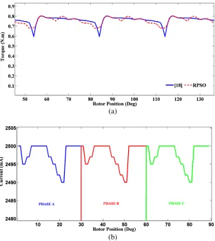
The optimized current profile of SRM drive is expressed in Table 2. Fig. 8(a) shows torque profile comparison of RPSO and [18] for drive optimization where the RPSO optimized currents profile is illustrated in Fig. 8(b).
As seen from Table 2 and Fig. 8(a), the reduction made by the proposed method in the ripple factor for optimized current profile is 34% with respect to previous work [18]. This shows the effectiveness of the proposed method for the optimization of the SRM structure.
A Texas Instrument SRM drive is designed to have accuracy about 0.25%. As our SRM uses 2.5 A current supplier connected to the stator windings, therefore the accuracy is about 6 mA. Unlike the RPSO model, there is no robustness in the suggested optimized model of [18] as shown in Table 2. In Fig. 9, the optimized drive with RPSO comes with 4 random samples in a 2-D space, which represents the average torque and torque ripple in each axis where the parameter of optimized SRM drive is randomly changed by 6 mA. Table 2 shows the worst results of random samples and objective function values deviation. As seen, the worst deviation of objective functions for RPSO solution (4%) is better than [18] (24%) that shows the proposed method has better robustness.
(a)
(b)
Figure 8. Drive optimization: (a) Torque profile comparison of RPSO and [18], (b) RPSO optimized currents profile.
Table 2. Current value of optimised result and the worst random neighbor and the deviations of worst neighbor from the main result.
Drive Model Tor
que
Ave (N.M) Tor
q
ue
R
ipple
Scalar Deviation from RPS
O
mA mA mA mA mA mA mA mA mA mA mA mA mA mA mA
2500 2500 2500 2500 2500 2500 2500 2500 2500 2500 2500 2500 2500 2500 2500
0.74 0.24 -
2500 2495 2497 2500 2500 2500 2500 2497 2495 2492 2490 2500 2500 2500 2500
0.75 0.16 -
Worst Random Neighbor
0.76 0.20 4%
0.75 0.43 24% 1o 3o 5o 7o 9o 11o 13o 15o 17o 19o 21o 23o 25o 27o 29o
rand * ±6 mA + RPSO Parameters
rand * ±6 mA + [18] Parameters [18]
(a) (b)
Figure 9. Robustness comparison in drive optimization: (a) RPSO current profile design and 4 random neighbors, (b) constant current profile ([18]) design and 4 random neighbors.
is better in both torque and ripple than [18]. Also the random neighbors do not exceed more than only 5% from RPSO solution, then their robustness is provable.
5. CONCLUSION
In this article, the RPSO algorithm has been employed to solve SRM geometry and drive robust optimization problems. A MATLAB linked Finite Element Software, COMSOL 4.2, has been used to torque calculation and objective functions evaluation.
The proposed robust optimization method was verified on two case studies for geometry and drive design. The results show an increase in the torque value, a decrease in torque ripple and an increase in robustness compared with the previous optimized SRM. As a proof for the robustness of the algorithm, the selected RPSO results have been compared to its neighbors. The deviation from the main model was renounceable, indicating the practicality for manufacturing of the selected geometry and drive. Therefore, robust optimization is necessary for the modern shape and drive design of all types of electric motors.
The future work, which will be investigated, is the multiobjective approach for the SRM design optimization. Moreover, material model will be investigated for the motor design optimization. Thereafter, an experimental study will be presented with details to verify the efficiency of these proposed design optimization methods.
REFERENCES
1. Arkadan, A. A., H. H. Shehadeh, R. H. Brown, and N. A. O. Demerdash, “Effects of chopping on core losses and inductance profiles of SRM drives,” IEEE Transactions on Magnetics, Vol. 33, No. 2, 2105–2108, 1997.
2. Vujicic, V. P., “Minimization of torque ripple and copper losses in switched reluctance drive,”IEEE Transactions on Power Electronics, Vol. 27, No. 1 388–399, 2012.
3. Fort, J., B. Skala, and V. Kus, “The torque ripple reduction at the drive with the switched reluctance motor,” 15th International Power Electronics and Motion Control Conference
(EPE/PEMC), DS2a.16-1–DS2a.16-4, IEEE, 2015.
4. Niapour, S. A., K. H. Mozaffari, M. Tabarraie, and M. R. Feyzi, “A new robust speed-sensorless control strategy for high-performance brushless DC motor drives with reduced torque ripple,”
5. Su, G.-W., M.-Y. Cheng, and W.-C. Chi, “Current loop controller design for torque ripple suppression of switched reluctance motors,” 2013 CACS International Automatic Control Conference (CACS), 496–500, IEEE, 2013.
6. Nakazawa, Y., K. Ohyama, H. Fujii, H. Uehara, and Y. Hyakutake, “Improvement of efficiency of switched reluctance motor by single pulse control based on linear torque equation,”15th European Conference on Power Electronics and Applications (EPE), 1–10, IEEE, 2013.
7. Singh, S. K. and R. K. Tripathi, “Minimization of torque ripples in SRM drive using DITC for electrical vehicle application,”2013 Students Conference on Engineering and Systems (SCES), 1–5, IEEE, 2013.
8. Kalaivani, L., P. Subburaj, and M. W. Iruthayarajan, “Speed control of switched reluctance motor with torque ripple reduction using non-dominated sorting genetic algorithm (NSGA-II),”
International Journal of Electrical Power & Energy Systems, Vol. 53, 69–77, 2013.
9. Mikail, R., I. Husain, Y. Sozer, M. S. Islam, and T. Sebastian, “Torque-ripple minimization of switched reluctance machines through current profiling,” IEEE Transactions on Industry Applications, Vol. 49, No. 3, 1258–1267, 2013.
10. Dowlatshahi, M., S. M. Saghaeian Nejad, and J. Ahn, “Torque ripple minimization of switched reluctance motor using modified torque sharing function,” 2013 21st Iranian Conference on Electrical Engineering (ICEE), 1–6, IEEE, 2013.
11. Ma, C., L. Qu, and Z. Tang, “Torque ripple reduction for mutually coupled switched reluctance motor by bipolar excitations,” 2013 IEEE International Electric Machines & Drives Conference
(IEMDC), 1211–1217, IEEE, 2013.
12. Somesan, L.-E., E. Padurariu, and I.-A. Viorel, “Two simple analytical models, direct and inverse, for switched reluctance motors,”Progress In Electromagnetics Research M, Vol. 29, 279–291, 2013. 13. Bist, V. and B. Singh, “A brushless DC motor drive with power factor correction using isolated
zeta converter,” IEEE Transactions on Industrial Informatics, Vol. 10, No. 4, 2064–2072, 2014. 14. Jin, Y., “Advanced control methods for torque ripple reduction and performance improvement in
switched reluctance motor drives,” PhD diss., 2014.
15. Youssef, M. Z., “Design and performance of a cost-effective BLDC drive for water pump application,”IEEE Transactions on Industrial Electronics, Vol. 62, No. 5, 3277–3284, 2015. 16. Parackal, R. and R. A. Koshy, “PV powered zeta converter fed BLDC drive,” 2014 Annual
International Conference on Emerging Research Areas: Magnetics, Machines and Drives
(AICERA/iCMMD), 1–5, IEEE, 2014.
17. Abraham, A. and A. Mathew, “Implementation of a novel PFC Cuk rectifier fed brushless DC motor drive,” 2014 Annual International Conference on Emerging Research Areas: Magnetics,
Machines and Drives (AICERA/iCMMD), 1–5, IEEE, 2014.
18. Navardi, M. J., B. Babaghorbani, and A. Ketabi, “Efficiency improvement and torque ripple minimization of switched reluctance motor using FEM and seeker optimization algorithm,”Energy Conversion and Management, Vol. 78, 237–244, 2014.
19. Xia, C., Y. Xiao, W. Chen, and T. Shi, “Torque ripple reduction in brushless DC drives based on reference current optimization using integral variable structure control,”IEEE Transactions on Industrial Electronics, Vol. 61, No. 2, 738–752, 2014.
20. Dowlatshahi, M., S. M. Saghaian Nejad, M. Moallem, and J. Ahn, “Torque ripple reduction of switched reluctance motors considering copper loss minimization,” 2014 IEEE International Conference on Industrial Technology (ICIT), 858–865, IEEE, 2014.
21. Buja, G., M. Bertoluzzo, and R. K. Keshri, “Torque ripple-free operation of PM BLDC drives with petal-wave current supply,”IEEE Transactions on Industrial Electronics, Vol. 62, No. 7, 4034–4043, 2015.
22. Gao, X., X. Wang, Z. Li, and Y. Zhou, “A review of torque ripple control strategies of switched reluctance motor,” International Journal of Control & Automation, Vol. 8, No. 4, 103–116, 2015. 23. Balaji, M. and V. Kamaraj, “Evolutionary computation based multi-objective pole shape
Systems, Vol. 43, No. 1, 63–69, 2012.
24. Tavakkoli, M. A. and M. Moallem, “Torque ripple mitigation of double stator switched reluctance motor (DSSRM) using a novel rotor shape optimization,”2012 IEEE Energy Conversion Congress and Exposition (ECCE), 848–852, IEEE, 2012.
25. Ren, Z., D. Zhang, and C. S. Koh, “Multi-objective worst-case scenario robust optimal design of switched reluctance motor incorporated with FEM and Kriging,” 2013 International Conference on Electrical Machines and Systems (ICEMS), 716–719, IEEE, 2013.
26. Chiariello, A. G., A. Formisano, R. Martone, and F. Pizzo, “Gradient-based worst case search algorithm for robust optimization,” IEEE Transactions on Magnetics, Vol. 51, No. 3, 7205004, 2015.
27. Hong, W. C., “Chaotic particle swarm optimization algorithm in a support vector regression electric load forecasting model,”Energy Conversion and Management, Vol. 50, No. 1, 105–117, 2009. 28. Xiao, S., Y. Li, M. Rotaru, and J. K. Sykulski, “Six sigma quality approach to robust optimization,”
IEEE Transactions on Magnetics, Vol. 51, No. 3, 7201304, 2014.
29. Mirjalili, S., A. Lewis, and S. Mostaghim, “Confidence measure: A novel metric for robust meta-heuristic optimisation algorithms,” Information Sciences, Vol. 317, 114–142, 2015.
30. Lei, G., T. Wang, J. Zhu, Y. Guo, and S. Wang, “System level design optimization method for electrical drive systems — Robust approach,”IEEE Transactions on Industrial Electronics, Vol. 62, No. 8, 4702–4713, 2015.
31. Malarvizhi, K. and M. Kumar, “Particle swarm optimization tuned BELBIC controller for 8/6 SRM operation,” 2015 2nd International Conference on Electronics and Communication Systems (ICECS), 904–909, IEEE, 2015.
32. Angeline, P. J., “Evolutionary optimization versus particle swarm optimization: Philosophy and performance differences,” Evolutionary Programming VII, 601–610, Springer, Berlin, Heidelberg, 1998.
33. Li, M., R. Silva, F. Guimar˜aes, and D. Lowther, “A new robust dominance criterion for multiobjective optimization,”IEEE Transactions on Magnetics, Vol. 51, No. 3, 8201504, 2015. 34. Mirjalili, S. and A. Lewis, “Novel performance metrics for robust multi-objective optimization
![Figure 6. Design comparison of RPSO and [18] in geometry optimization: (a) Torque profile, (b)Geometry of SRM.](https://thumb-us.123doks.com/thumbv2/123dok_us/1987451.1262877/8.612.95.525.542.708/figure-design-comparison-geometry-optimization-torque-prole-geometry.webp)
![Figure 7. Robustness comparison in geometry optimization: (a) RPSO design and 4 random neighbors,(b) [18] design and 4 random neighbors.](https://thumb-us.123doks.com/thumbv2/123dok_us/1987451.1262877/9.612.147.467.82.285/figure-robustness-comparison-geometry-optimization-design-neighbors-neighbors.webp)
![Figure 9. Robustness comparison in drive optimization: (a) RPSO current profile design and 4 randomneighbors, (b) constant current profile ([18]) design and 4 random neighbors.](https://thumb-us.123doks.com/thumbv2/123dok_us/1987451.1262877/11.612.140.465.77.273/robustness-comparison-optimization-prole-randomneighbors-constant-prole-neighbors.webp)