“Home Automation Using Plc”
Piyush Bahad*
1, Chetan Tembhurnikar*
2, Nikhil Nikose*
3, Mayur Bhati*
4*Department of Electrical Engineering
Jhulelal Institute of Technology, Rashtrasant Tukdoji Maharaj Nagpur University, Nagpur (M.S), India – 441110
[email protected]*1 , [email protected]*2 , [email protected]*3 , [email protected]*4
ABSTRACT
Now-a-days, the rapid development of information technology has brought powerful changes to the structure of automation system, and makes people to set a higher request to security, comfort and efficiency of home environment. Intelligent household devices have become a research focus in home automation industry, for how to let television set, refrigerator, lightings, alarm sensor, and other home devices work efficiently and easy to be utilized. Through the integration of information technologies with the home environment, systems and appliances are able to communicate in an integrated manner which results in convenience, energy efficiency, and safety benefits. In this research paper we are targeting to automate the home appliances using PLC. The aim of this research paper is to get knowledge about the PLC used in industries and implementing it for energy saving purpose at home.
Keywords: PLC, Automation, Sensor, Security, Energy saving, Troubleshooting, Controller.
I.
INTRODUCTION
Now-a-days, we can see that every sector is going in the way to automation, whether it might be aerospace, industrial, manufacturing, automobile, etc [1]. Let us consider one example, in summer season we all like to have cold drinks, now we noticed that all the bottles in tray are filled with same level. The reason behind it is automation. In the industries where this is bottles are filled with cold drink, we can see that empty bottles coming on conveyer belt, then bottle stops at the right place, then it is filled with cold drink up to the appropriate level, then that bottles is pushed forward for further processes. This process goes again and again for
number of bottles. This whole process in the industry in controlled by the device called as Programmable Logic Controller i.e. PLC.
For example, a scenario such as person left the room without switching off the lights, so by using this project lights can be turned off automatically. Sophisticated control can be done with computational abilities. Programming is easier and reduces downtime through troubleshooting ability. Reliability and durability of the components make PLCs likely to operate for years. The control of the home based appliances such as automatic door, lights, fans, water pump, etc. without human intervention.
II.
LITERATURE SURVEY
A. S.sujutha [3] has developed the control of the home based appliances such as water heater, air conditioner, exhaust fan, light etc. without human interventions shown in Figure 1. For example, if the room is darker or insufficient light, the sensor senses it and commands the PLC to switch on the light. Similarly, if the smoke is detected, exhaust fan will be switched on. The Logo PLC can get four inputs and four outputs, the extensions could be made by connecting to main PLC. It has lithium ion battery, which provides power supply for 26 days. The water level in the tank will be maintain a level using a float switch ,when the float switch goes to a particular lower level ,the command goes to PLC and switches on the motor ,when it goes to particular higher limit, it switches of the motor.
Fig. (1)
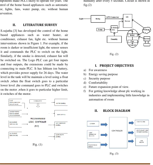
B. Dhakkad kunal [6] has developed the home automation using arduino microcontroller in which they have measured temperature and humidity. We have set time by which it continuously senses temperature and humidity. In the screenshot given below, it continuously senses temperature and humidity after every 5 seconds. Circuit is shown in fig.(2)
Fig. (2)
I.
PROJECT OBJECTIVES
a) For awareness
b) Energy saving purpose c) Security purpose d) Comfortability
e) Future expansion point of view.
f) For getting knowledge about plc working in industries and implementing little knowledge in automation of room
II.
BLOCK DIAGRAM
Above figure (3) shows the block diagram of prototype model. In the left hand side all the inputs from PIR sensor, LDR and temperature sensor are connected to controller. The controller processes the input as per program stored in it outputs required outcomes that is automatic door opening, lights on/off and intensity control and fan on/off.
III.
PROGRAMMABLE LOGIC CONTROLLER
A programmable logic controller (PLC)
or programmable controller is an industrial digital computer which has been ruggedized and adapted for
the control of manufacturing processes, such
as assembly lines, or robotic devices, or any activity that requires high reliability control and ease of programming and process fault diagnosis. The formal definition of PLC given by NEMA is that Programmable Logic Controller is a digital controlled electronic device which has number input pins. The input to this input pins is given by relay, contactor, etc. PLC has programmable memory in which program is stored by user. According to program stored in the memory PLC processes varies outputs like arithmetic, logic controlling, timing, counting, etc. Both the PLC and its peripheral devices are designed so that they can be easily integrated with the industrial control system.[4]
Fig.(4) Programmable Logic Controller
Fig.(5) Major Components of PLC
IV.
CIRCUIT DIAGRAM
In the block diagram shown above, in the left hand side we have PIR sensor as an input. PIR sensor works on 5v dc. PLC works on 230/120v AC.PLC has inbuilt AC to DC converter which converts 230v AC to the 24v DC. This 24v DC is regulated to 12v DC by using IC 7812. Capacitor is used to reduce the current from 10 amps to 2 amps. Now 12v DC is regulated to 5v DC by using IC7805. This 5v DC is given to the PIR Sensor for operation. As well as this 5v DC is given to the L298N Motor Driver kit as a supply. L298N Motor Driver is used to convert the output of PIR Sensor that is 3.2v DC to 24v DC. Whenever PIR senses anybody’s presence it gives output to L298N Driver kit of 3.2v DC and L298N driver converts this 3.2v to 24v DC which is a input to PLC
it. After solving the program PLC gives output of 24v DC to the RS-24 Relay. As soon as RS-24 relay gets the input that is 24v DC from the PLC, its normally closed contact gets open and normally open contact gets closed and the relay is energized. Once the relay is energized then it pulls the plunger to close the 230 v AC supply circuit and light and fan gets 230v AC Supply. Hence the light and fan start it operation.
After successful implementation of the project in live, the light and fan turns on when someone is present in the room. When there is no body in the room lights gets turn off and after 15 sec fan get turn off.
V.
PROGRAMMING
Fig.(6) Ladder Programming of PLC
The most common method used for programming PLCs is based on the ladder diagrams. Writing a program is then equivalent or resembles to drawing a switching circuit. The ladder diagram consists of two vertical lines on either side representing the power rails which are positive and neutral. Circuits are connected in the rungs of the ladder which are horizontal, between these two rails. Ladder logic was originally a written method to document the design and construction of relay racks as used in manufacturing and process control. Each device in the relay rack would be represented by a symbol on the ladder diagram with connections between those devices shown Ladder logic acts as a programming language that represents a program in the form of graphical diagram based on the circuit diagrams of relay logic hardware and used in industrial control applications. The name Ladder Logic is appropriate as it resembles a ladder with two vertical rails on either
side with a series of horizontally connected rungs between them. The system in the ladder diagram form will be programmed into the PLC. Once the programs have been downloaded into PLC, it can be monitored in the Diagram Workspace during execution. The PLC provide the easy user interface to download the program, to upload the program, and to go back at online mode to see program desirable state
VI.
HARDWARE
Fig.(7) Hardware circuit
VII.
COMPARISION OF PLC WITH OTHER
CONTROLLER
Home automation can be done other type of controller also. The initial cost of installation with the use of PLC is more than other controller. PLC is superior as compared to other controller [3]. Few reasons as follows:
1. Safety - PLCs manufacturers also provide safety
features such are SIL certification as per customer requirement for Protection/Emergency Shutdown System.
2. Utility - PLCs can interface with a large no of
drives and actuators ranging from analog and digital to special type such as speed measurement and RTD/thermocouples etc.
3. Inbuilt Function and Algorithms - There are
4. Diagnostic features - PLC have inbuilt diagnostics for LAN failure, power failure, logic issues, Disconnection of I/Os and alarms.
5. Industrial Grade - PLCs are designed with
tolerance to withstand various hazardous conditions for Industries such as Electromagnetic interference, high temperature, power fluctuation etc.
6. Modular Design - The PLC capacity and
design can easily modified to suite customer need post implementation stage. This is not feasible with relays or microcontroller based solutions.
7. Large capacity - The PLC nowadays have a
capacity of 3000+ I/Os that is analog and digital combined. This is maintained through a central engineering station for ease of control.
8. Easy Maintenance and Spares - Due to
modular design the trouble shooting is easier and the no of spares requirement is reduced and easily manageable.
VIII.
ADVANTAGES
1. Ease of programming
2. Ease of interfacing devices and sensors
3. Wide range of operating voltages- both ac and dc 4. Number of inputs and outputs that can be connected
much larger than microcontrollers
5. The provision of both discrete and analog I/Os 6. Reliable, less complex than microcontroller 7. Protection mechanism is inbuilt in PLC 8. Communication medium is available.
IX.
APPLICATIONS
1. With modifications in programming a PLC and interfacing of various sensors and appliances, PLCs can be made to handle many tasks pertaining to home automation.
2. Eliminating the need to walk around the house turning off lights before exiting the home or going to sleep, turning off all house lights without the touch of a single button, it helps in energy saving also.
3. Electrical energy can be saved by automatic turning off the appliances when there is no body in the room.
X.
FUTURE SCOPE
1. Zone your heat and automatically adjust it to make home comfortable
2. Set up home surveillance
3. Security-monitoring doors and windows and alarm system
4. Automatic water heater
5. Automatic water sprinkling in garden
XI.
CONCLUSION
1. This project aims to automate the basic necessities required in a generic home using a much simpler system-a plc, rather than using complicated microcontrollers.
2. Also, adding more modules to the expansion slots of a plc doesn’t need to reprogram the plc from
scratch, as it is needed in
microcontrollers/embedded systems
XII.
REFERENCE
1. L.a. Bryan and e.a. Bryan, “PROGRAMMABLE
CONTROLLERS: THEORY AND IMPLEMENTATION” ,
indutrial text, chicago,il,1988,pp.20-40
2. S.sujatha ; et.al., “HOME AUTOMATION USING PLC”,(ncrte 2k16), volume 5,special issue 1,march 2016
3. Irmak, e.; kabalci, e.; kose, a., "DESIGN AND IMPLEMENTATION OF A COMPUTER INTERACTED SMART HOME SYSTEM BASED ON PLC" application of information and communication technologies (aict), 2010 4th international conference on, vol., no., pp.1,5, 12-14 oct. 2010
4. Multidisciplinary Journal of Research in Engineering and Technology, Volume 1, Issue 1 (April 2014) Pg. 111-118
5. Dhakad Kunal ; et.al. “Smart Home Automation using IOT” International Journal of Advanced Research in Computer and Communication Engineering Vol. 5, Issue 2, February 2016