Flexible CPW-Fed Split-Triangular Shaped Patch Antenna
for WiMAX Applications
Ketavath Kumar Naik* and Dattatreya Gopi
Abstract—In this paper the analysis and investigations are carried out on portable antennas for worldwide interoperability for microwave access (WiMAX) applications of flexible coplanar waveguide (CPW)-feed split-triangular shaped patch (STSP). The proposed STSP antenna is fabricated from polyimide substrate material having the dimension of 18×20×0.1 mm3(volume is 36 mm3). It resonates at 3.55 GHz frequency of a reflection coefficient (S11) of −24.45 dB and offers impedance bandwidth of
580 MHz (3.3–3.88 GHz) with a gain of 2.06 dBi. The STSP antenna has small size, light weight, low volume, and is flexible for WiMAX applications. Simulation and measured results of the proposed STSP antenna are in close agreement.
1. INTRODUCTION
Flexible antennas have gained considerable attention in terms of convenient integration and are compatible with the other microwave components [1]. The design of low profile flexible microstrip patch antenna (MPA) with conformal characteristics is needful for fulfilling the requirements of wireless wearable and bendable devices, radars, space crafts, air crafts and bio-medical applications. Bandwidth has been improved with different iteration techniques in the antenna design. A number of microstrip antennas with different geometrical configurations are experimentally verified for size reduction and bandwidth enhancement [2–4]. A miniaturization of CPW-fed slots using reactive terminations and truncated bilateral ground plane [2] was proposed to reduce the antenna size. Microstrip antennas have the disadvantage of low efficiency and limited bandwidth reported in [3], due to the influence of different losses such as feeding surface wave and dielectric. Therefore, the method of using compact and broadband antennas without degrading performance is one of the focuses of flexible antenna design. The concentric circular ring slot patch antenna [4] is designed with a defected ground structure (DGS) to improve the gain.
In the literature, different monopole antenna structures are proposed to multi, triple, and dual-band WLAN/WiMAX applications, reported in [5–7]. A triangle-shaped monopole CPW-fed multi-band antenna [5] is proposed for wireless applications. Meander line is used to resonate the antenna for dual-band frequencies. A compact dual wide-band fractal Koch printed antenna [8] is presented, and a tuning slot is embedded for filter action to get desired wide-band operation. A CPW-fed monopole antenna [7] with dimensions 25×25×0.8 mm3 was proposed to triple bands of restricted frequency overlapping and noise interference to improve radiation performance.
In [8] a novel compact CPW-fed antenna (25×20×1.6 mm3) was proposed for broadband tuning. A CPW-fed compact monopole antenna [9] was proposed with two I-shaped and U-shaped slots, and it was fabricated from an FR-4 substrate with dimensions of 23×30×0.75 mm3. However, these designs have large dimensions and are not compatible with flexible devices.
Received 3 June 2018, Accepted 28 June 2018, Scheduled 17 July 2018
* Corresponding author: Ketavath Kumar Naik ([email protected]).
polyimide-based multiband flexible antenna [15] was proposed to operate four frequency bands. A CPW-fed fishtail-shaped flexible antenna [16] was proposed at WiMAX and X-band applications. Stepped impedance lines are introduced to achieve better impedance matching and wideband characteristics. Although the reported antennas in Table 5 show multiple, triple, dual-band frequencies, in comparison the proposed STSP antenna is a flexible one with small size, simple geometry and resonates at single frequency band with wider bandwidth and acceptable gain.
In this paper, a compact flexible CPW-fed split-triangular patch antenna is proposed. The antenna offers 580 MHz impedance bandwidth from 3.3 GHz to 388 GHz and covers WiMAX frequency band. The proposed antenna is small in size (18×20×0.1 mm3) and offers a size reduction of 72%. The
prototype of the proposed antenna is fabricated and tested experimentally.
2. ANTENNA DESIGN
The compact flexible CPW-fed split-triangular shaped patch (STSP) antenna is considered for WiMAX applications, shown in Fig. 1. The evolution of STSP antenna is shown in Fig. 2. For conformability and flexibility, the antenna was fabricated on a kapton polyimide film having a dielectric constant (εr) 3.5 and loss tangent δ 0.008.
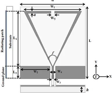
Figure 1. Geometry of split-triangular shaped patch (STSP) antenna.
The proposed STSP antenna resonant frequency (fr) can be derived from [17]:
fr = 2v
6se√εr (1)
se = W1
1 + 2.199 h W1 −
12.85 h W1√εr
+ 16.43 h W1εr
+ 6.182
h
W1
2
−9.802 1
εr
h
W1
2
(2)
where v is the speed of electromagnetic waves in free space, W1 the triangular side arm length, and
(a) (b) (c)
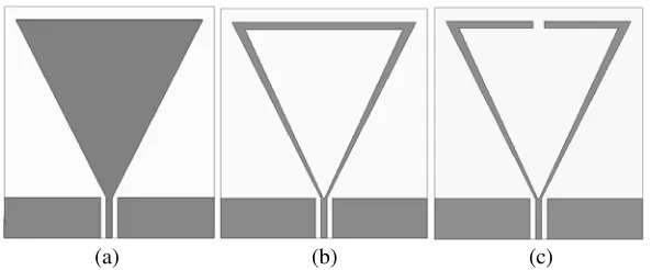
Figure 2. Geometry evaluation of proposed split-triangular patch (STSP) antenna.
As shown in Fig. 1, the length and width of the substrate are L and W and for triangular arm the side lengths are L1 and W1; the split width of the triangular arm is denoted by W5;his the thickness of
the radiating element. The split-triangular patch antenna is fed through CPW transmissions of a 50 Ω impedance line of width W3 which simplifies fabrication process by considering ground of L2×W2 and
radiating patch on only one side of the substrate. To resonate only at one frequency band and to operate in the WiMAX range, a split-triangular patch antenna has been considered. It is a less metalized and low volume antenna. The evolution process is presented in Fig. 2.
Parametric analysis has been carried out with different flare angles. As the flare angle slightly increases, there is a shift in frequency. The triangular radiator with split is designed to operate at 3.55 GHz frequency of a flare angle (f) 45◦. In order to meet desired band of frequencies, the flare angle of radiator can be easily adjusted to make the antenna flexible and scalable. The detailed optimized dimensions of the flexible CPW-fed split-triangular shaped patch (STSP) antenna is shown in Table 1.
Table 1. Optimized dimensions of split-triangular shaped patch (STSP) antenna.
Parameters Values in (mm) Parameters Values in (mm)
L 20 W3 1
L1 16 W4 3
L2 3 W5 1
W 18 h 0.1
W1 16 a 1
W2 7.5 f 45◦
3. RESULTS AND DISCUSSIONS
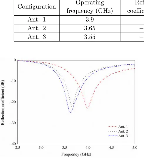
The evolution process of STSP patch antenna is presented in Fig. 2 to achieve the desired WiMAX band frequency. The first evolution of the STSP antenna consists of a triangular patch which resonates at 3.9 GHz frequency of a reflection coefficient of−22.91 dB, and the area of the metallization in antenna 1 (Ant. 1) is 47.7%. In the second evolution process, a triangle-shaped patch is etched to form antenna 2 (Ant. 2) and to minimize the metallization with an area of 19.5%, and it radiates at 3.65 GHz with a reflection coefficient of−22.04 dB. In the final evolution (Ant. 3), a small rectangular split is considered with width of 1 mm which is removed from center of side length of Ant. 2. The proposed antenna (Ant. 3) radiates at 3.55 GHz frequency with −24.45 dB reflection coefficient. The proposed antenna patch radiating area is about 19.3%.
Ant. 3 3.55 −24.45 580 2.06
Figure 3. Reflection coefficient response of STSP antenna for each evolution process.
Figure 4. Prototype of fabricated split-triangular patch (STSP) antenna.
Ant. 3. The frequency response shifts 250 MHz to lower end of Ant. 1 compared to Ant. 3.
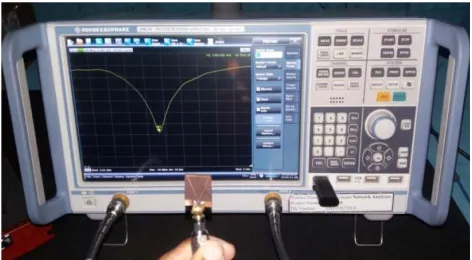
The STSP antenna models are designed and simulated using CST microwave studio. Photographs of fabricated STSP antenna are presents in Fig. 4. A photograph of reflection coefficient (S11) plot
is shown in Fig. 5 with a ZNB-20, R&S (vector network analyzer) for measurements of the proposed antenna.
The reflection coefficient (S11) responses to the proposed antenna at different flare angles are shown
in Fig 6. As the flare angle increases, the frequency shifts towards lower end. Forf1 = 40◦ andf2= 50◦,
the resonant frequencies are observed at 3.8 GHz and 3.56 GHz with reflection coefficients of −21.2 dB and −20.8 dB, respectively. The bandwidths are observed as 310 MHz and 350 MHz for the two flare anglesf1 and f2. The desired operating frequency is obtained atf = 45◦ flare angle.
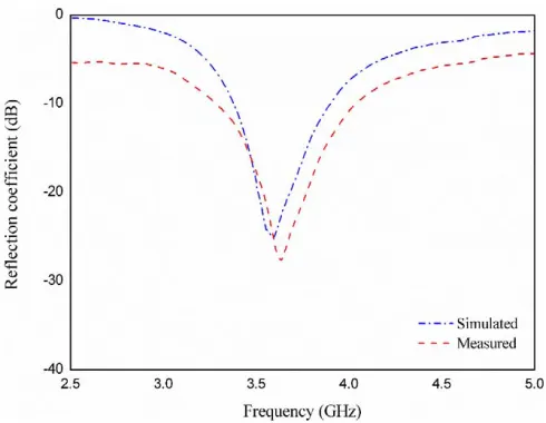
An STSP antenna photograph of bent is shown in Fig. 7. The comparison of the STSP antenna simulated reflection coefficient at different center angles in convex bent configuration is shown in Fig. 8. It is observed that compared to planar configuration for 10◦ center angle, the resonant frequency shifts towards higher end by 10 MHz with improved reflection coefficient. A frequency shift of 10 MHz is observed at 20◦ center angle towards the lower end of improved reflection coefficient. Similarly, at 40◦ and 50◦ center angles, the frequency shifting towards lower end 20 MHz, 10 MHz is observed. However, there is a no frequency shifting is observed at 30◦ bent angle. The analysis data are shown in Table 3. The measured and simulated reflection coefficients of the proposed antenna are shown in Fig. 9. It resonates with 3.61 GHz frequency of −26.85 dB reflection coefficient and an impedance bandwidth of 20.4% (3.3–4.05 GHz). It is observed that compared to simulated reflection coefficient, the measured one has small deviations. The deviations are observed due to parametric losses. The simulated and measured data are presented in Table 4.
Figure 5. Photograph of Vector network ana-lyzer (VNA) with measured reflection coefficient of split-triangular shaped patch (STSP) antenna.
Figure 6. Reflection coefficient response to different flare angles of split-triangular shaped patch (STSP) antenna.
Figure 7. Photograph of STSP antenna at bent position.
Figure 8. Reflection coefficient response from bending characteristics of STSP antenna.
Table 3. Comparison of reflection coefficient and gain for planar and bent configuration of proposed antenna.
Convex configuration
Operating frequency (GHz)
Reflection
coefficient (dB) Gain (dBi)
Surface current distributions (A/m)
Planar 3.55 −24.45 2.06 236.6
Bent at 10◦ 3.56 −33.42 2.05 231.5
Bent at 20◦ 3.54 −38.01 2.05 227.3
Bent at 30◦ 3.55 −28.45 2.04 224.9
Bent at 40◦ 3.53 −43.94 2.04 230.1
Figure 9. Reflection coefficient of STSP antenna with simulated and measured data.
(a) (b) (c)
Figure 10. 3-D gains plots of STSP antenna for each evaluation process at 3.55 GHz frequency. (a) Ant. 1, (b) Ant. 2, (c) Ant. 3.
Table 4. Performance of STSP antenna.
Model
Operating frequency
(GHz)
Reflection coefficient
(dB)
Impedance bandwidth
(GHz)
Bandwidth (MHz)
Impedance bandwidth
(%)
Gain (dBi)
Simulated 3.55 −24.45 3.3–3.88 580 16.1 2.06
Measured 3.61 −26.85 3.3–4.05 750 20.4 1.82
observed at 3.55 GHz frequency is 2.06 dBi for Ant. 2 and Ant. 3. The gain is slightly increased for Ant. 2 to Ant. 3.
The measurement setup of the proposed STSP antenna is shown in Fig. 11. The transmitting antenna (horn antenna) and receiving antenna (STSP antenna) are presented in an anechoic chamber. Figure 12 shows the normalized simulated and measured far-field radiation characteristics of both
E-plane (X-Z plane) and H-plane (Y-Z plane) at 3.55 GHz frequency. It is clearly shown that the radiations are in semi-omnidirectional patterns of E and H-planes with −3 dB beamwidths of about 98◦ and 125◦. Front-to-back ratios are observed as 6 dB for both the planes.
Figure 11. Chamber measurement setup of STSP antenna.
E-plane H-plane
Figure 12. E-field,H-field radiation patterns of STSP antenna at 3.55 GHz frequency.
(a) (b) (c)
Figure 13. Surface current distributions of each evaluation process of STSP antenna at 3.55 GHz frequency. (a) Ant. 1, (b) Ant. 2, (c) Ant. 3.
(d) (e)
Figure 14. Surface current distributions of STSP antenna at 3.55 GHz frequencies. (a)10◦, (b) 20◦, (c) 30◦, (d) 40◦, (e) 50◦ bending angles.
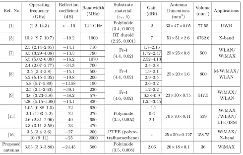
Table 5. Comparison of existing antenna models to the proposed STSP antenna.
Ref. No Operating frequency (GHz) Reflection coefficient (dB) Bandwidth (MHz) Substrate material
(εr,δ)
Gain (dBi)
Antenna Dimentions
(mm3)
Volume
(mm3) Applications
[1] (2.2–14.3) <−10 12.1 GHz Polyimide
(3.4, 0.002) 2 33×47×0.05 77.55 UWB
[3] 10.2 (9.7–10.7) −19.2 1000 RT duroid
(2.25, 0.001) 7 51×51×2.6 6762.6 X-band
[7]
2.5 (2.14–2.85) −14.1 710
Fr-4 (4.4, 0.02)
1.7–2.15
25×25×0.8 500 WLAN/ WiMAX
3.5 (3.29–4.08) −13.5 790 1.72–2.47
5.5 (5.02–6.09) −16.2 1070 2.52–4.13
[8]
2.4 (2.07–2.77) −34.3 700
Fr-4 (4.4, 0.02)
2.4–2.8
25×20×1.6 800 M-WiMAX/ WLAN
3.5 (3.3–3.8) −15.1 500 1.9–2.1
5.2 (5.15–5.35) −19.8 200 2.9–3.5
5.8 (5.7–5.89) −13.58 190 2.6–3.2
[9]
2.5 (2.4–2.63) −30.1 230
Fr-4 (4.6, 0.02)
1.2–2.2
23×30×0.75 517.5 WiMAX/ WLAN
3.6 (3.23–3.8) −48.2 570 0.38–0.9
5.36 (5.15–5.98) −13.1 830 1.25–3.45
[15]
1.05 (0.88–1.5) −22 620
Polyimide (3.5, 0.002)
−1.2
70×70×0.11 539
WiMAX /WLAN/ LTE/ISM
2.1 (1.93–2.2) −22 270 0.6
2.6 (2.31–2.96) −40 650 2.1
3.3 (3.11–3.58) −23 470
-[16] 3.5 (3.4–3.6) −27 200 PTFE
(polyte-trafluoroethene) - 25×50×0.127 158.75
WiMAX/ X-band
10 (9–11) −25 2000
Proposed
antenna 3.55 (3.3–3.88) −24.45 580
Polyimide
(3.5, 0.008) 2.06 20×18×0.1 36 WiMAX
The comparison of the proposed STSP antenna to the existing models of simulated data is reported in Table 5. The proposed STSP antenna has small size, low volume (36 mm3) and resonates only in one
resonating band. The interference has been minimized due to one resonant band.
4. CONCLUSION
A flexible CPW-fed split-triangular shaped patch antenna is investigated to operate at WiMAX applications with good gain and wide bandwidth. The proposed STSP antenna resonates at 3.55 GHz with reflection coefficient −24.45 dB and gain 2.06 dBi. The measured results are in good agreement with simulated ones. The radiation patterns are observed bidirectional atE-plane and omnidirectional
H-plane. The proposed antenna is compact, small size, flexible and in low cost. It is suitable for WiMAX applications of low interference due to one resonant band.
ACKNOWLEDGMENT
This work was supported by the Science and Engineering Research Board (SERB), DST, New Delhi, India (Grant No. 1: SB/FTP/ETA-0179/2014, Grant No. 2: EEQ/2016/000754).
REFERENCES
1. Khaleel, H. R., H. M. Al-Rizzo, D. G. Rucker, and S. Mohan, “A compact polyimide-based UWB antenna for flexible electronics,” IEEE Antennas Wireless Propag. Lett., Vol. 11, 564–567, 2012. 2. Lai, C.-P., S.-C. Chiu, and S.-Y. Chen, “Miniaturization of CPW-fed slot antennas using reactive
terminations and truncated bilateral ground plane,”IEEE Antennas Wireless Propag. Lett., Vol. 11, 1072–1075, 2012.
3. Wang, X., M. Zhang, and S.-J. Wang, “Practicability analysis and application of PBG structures on cylindrical conformal microstrip antenna and array,” Progress In Electromagnetics Research, Vol. 115, 495–507, 2011.
4. Naik, K. K. and P. A. V. S, “Design of concentric circular ring patch with DGS for dual-band at satellite communication and radar applications,” Wireless Personal Communications, Vol. 98, 2993–3001, 2018.
5. Song, Y., Y.-C. Jiao, G. Zhao, and F.-S. Zhang, “Multiband cpw-fed triangle-shaped monopole antenna for wireless applications,” Progress In Electromagnetics Research, Vol. 70, 329–336, 2007. 6. Krishna, D. D., M. Gopikrishna, C. Anandan, P. Mohanan, and K. Vasudevan, “CPW-fed Koch fractal slot antenna for WLAN/WiMAX applications,” IEEE Antennas Wireless Propag. Lett., Vol. 7, 389–392, 2008.
7. Liu, H.-W., C.-H. Ku, and C.-F. Yang, “Novel CPW-fed planar monopole antenna for WiMAX/WLAN applications,” IEEE Antennas Wireless Propag. Lett., Vol. 9, 240–243, 2010. 8. Sun, X., G. Zeng, H.-C. Yang, and Y. Li, “A compact quadband CPW-fed slot antenna for
M-WiMAX/WLAN applications,” IEEE Antennas Wireless Propag. Lett., Vol. 11, 395–398, 2012. 9. Wang, P., G.-J. Wen, Y.-J. Huang, and Y.-H. Sun, “Compact CPW-fed planar monopole antenna
with distinct triple bands for WiFi/WiMAX applications,”Electron. Lett, Vol. 48, 357–359, 2012. 10. Anagnostou, D. E., A. A. Gheethan, A. K. Amert, and K. W. Whites, “A direct-write printed
antenna on paper-based organic substrate for flexible displays and WLAN applications,” Journal
of Display Technology, Vol. 6, 558–564, 2010.
11. Durgun, A. C., C. A. Balanis, C. R. Birtcher, and D. R. Allee, “Design, simulation, fabrication and testing of flexible bow-tie antennas,” IEEE Trans. Antennas Propag, Vol. 59, 4425–4435, 2011. 12. Khaleel, H. R., H. M. Al-Rizzo, and D. G. Rucker, “Compact polyimide-based antennas for flexible
displays,” Journal of Display Technology, Vol. 8, 91–97, 2012.
13. Hachi, A., H. Lebbar, and M. Himdi, “Flexible and conformal printed monopoles antennas,”
17. Helszajn, J. and D. S. James, “Planar triangular resonators with magnetic walls,” IEEE Trans.