Magnetically Tuned Two-Component Microwave Metamaterial
Oleg Rybin* and Sergey Shulga
Abstract—In this study, the effective magnetic response of magnetic metamaterial is considered in the microwave frequency range. The metamaterial is an infinite isotropic dielectric host medium with periodically embedded ferric cylindrical inclusions. It is assumed that the inclusions are partially magnetized by a dc bias magnetic field. The electromagnetic wave propagation is considered in the direction of bias magnetic field and transverse to bias magnetic field. It is shown that real part of the effective relative permeability can have Re(μeff)<0 or 0<Re(μeff)<1 or Re(μeff)>1 depending on
the value of bias field.
1. INTRODUCTION
Partially magnetized ferrites are widely used in microwave applications such as isolators [1], circulators [2], resonators [3], compact phase shifters [4], band-pass philters [5], band-stop philters [6] due to their large permeability tunable range, low or zero bias field, and fast tuning speed at micro-seconds. However, the relative permeability of partially magnetized conventional ferrites have μr >1 that can be accepted as a disadvantage taking into account a growing interest in antennas printed on metamaterial substrates with 0 < μr < 1 [7], and wireless power transfer systems fabricated with utilizing of mu-negative metamaterialsμr<0 [8]. Magnetic metamaterials or metaferrites can avoid the mentioned disadvantage. Indeed, as shown in work [9], real part of the effective relative permeability of array of magnetic metallic wires embedded in a dielectric medium can span any of the above mentioned value range depending on the value of bias magnetic field. However, the study in [9] is purely based on numerical solvers while analytical expressions for the effective magnetic responses are currently only developed for the case of fully magnetized inclusions [10, 11].
In this paper, the microwave approximations of effective magnetic response of an infinite isotropic dielectric host medium with periodically embedded ferric cylindrical inclusions partially magnetized by a dc bias magnetic field is derived for the first time. Two directions of propagation of a plane monochromatic electromagnetic wave are considered in this study — the direction of bias magnetic field and the direction transverse to bias magnetic field.
2. EFFECTIVE PERMEABILITY TENSOR
Consider two-component metamaterial as an infinite host dielectric medium (matrix) with peri-odically embedded ferric cylindrical inclusions with the unit cell of square cross section, Fig. 1, where r is the radius of inclusions, a the dimension of unit cell, m the relative permittivity of matrix, μm the relative permeability of matrix, i the relative permittivity of inclusion material,
μi the relative permeability of inclusion material, and −→B the vector of dc bias magnetic field.
Received 2 February 2017, Accepted 12 April 2017, Scheduled 20 April 2017 * Corresponding author: Oleg Rybin ([email protected]).
Figure 1. Unit cell of the metamaterial.
Let us assume that the bias magnetic field is applied along the cylinder axes. Then the microwave approximation for effective permeability tensor of the metamaterial is given by [12].
ˆ
μeff = μ0
μ 0 −ik 0 μy 0
ik 0 μ
, (1)
μ = 1 3+
2 3
√
μ+μ−1− α32+ ˜μα32, (2)
μ+ = 1 +F ωΣ
ω0+iωF αin−ω,
(3)
μ− = 1 +F ωΣ
ω0+iωF αin+ω,
(4)
˜
μ = 1 +F ωΣ(ω0+iωF αin)
(ω0+iωF αin)2−ω2
, (5)
μy = 1 +F ωΣ
(ω0+iωF αin)
(ω0+iωF αin)2−ω2
1− α32, (6)
k = α3F ωΣ
ω0+iωF αin−ω,
(7)
α3 = ⎧ ⎨ ⎩
1, M =Ms,
M
MΣ, M =Ms,
(8)
where μ0 is the permeability of vacuum, γ the gyromagnetic ratio, F = πr2/a2 the metal volume fraction,ω the angular frequency of electromagnetic wave,αinthe damping factor of inclusion material,
M the magnetization, Ms the magnetization saturation of inclusion material, ω0 =μ0γH0 the Larmor or precession frequency, H0 the dc magnetic field strength on the surface of inclusions, ωΣ =γμ0MΣ
the intrinsic precession frequency, andMΣ the effective magnetization of the metamaterial given by [11]
MΣ= ω0
γ
μ2ξ−3μξ−2−
1 + 16μ4ξ+ 2μ3ξ−3μ2ξ+ (ω/ω0)2
3−15μ4ξ−8μ3ξ+ 8μ2ξ+ 12μξ −1/2
1 + 3μξ ,
(9)
where
μξ=μm
1− F
1 +i/πμ0μmr2σω
whereσ is the conductivity of inclusion material.
Equation (7) is, in fact, the high frequency approximation of k. It means that Eq. (7) is valid for
ωΣ/ω << 1 and ω0/ω << 1. In order to obtain the expression of k valid for whole of the considered frequency range, it is necessary to take into account that:
lim
M→Msk=F
ωγμ0MΣ
(ω0+iωF αin)2−ω2
, (11)
where the right part of Eq. (11) is the microwave approximation of k for the case of fully magnetized inclusions obtained in work [12]. Taking into account Eq. (11), it is logically to conclude:
k=α3F ωΣω
(ω0+iωF αin)2−ω2
. (12)
It is important to mention that Eq. (12) is irrespective of the shape of inclusions, and Eq. (12) is obtained for the first time.
On the analogy of work [9], in our study we consider air host medium to prevent losses due to the dielectric (μm = 1 =m).
Taking into account 2-D symmetry of the considered metamaterial medium, we can write the tensor of effective permeability in the form:
ˆ
eff =0
0 0
0 yy 0 0 0
, (13)
whereis obtained in [11], and yy is given in [13] for the case of very thin PEC cylinders.
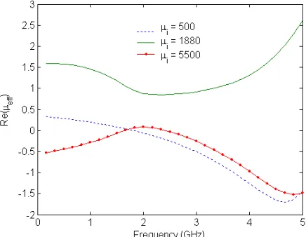
Throughout this study, three magnetization modes are considered: 1) the case of maximal value of relative permeability of the inclusions (H0 = 120A/m, μi = 5500, M = 6.5988·105A/m); 2) the case of fully magnetized inclusions (H0 = 1.6·105A/m, μi = 500, M = 1.7189·106A/m); 3) the intermediate case (H0 = 600A/m,μi = 1880,M = 3.661·105A/m). It is also assumed thata= 0.001m,
r = 0.00034m, αin = 0.5. The above values of a and r are chosen to reach the maximum permissible value of metal volume fraction defined in the Effective Medium Theory of work [11]. The second magnetization mode is also considered to take the appropriate results from work [11].
3. WAVE PROPAGATION IN DIRECTION OF BIAS
Consider a propagation of plane monochromatic electromagnetic wave in the direction of bias magnetic field that is parallel to the axis y. In this way, y-dependence of electromagnetic field components is
e−iβy (∂/∂x= 0 =∂/∂z):
− →
E =−→E0e−iβy, −→E0=E0xx0→− +E0y−→y0+E0z−→z0,
− →
H =−→H0e−iβy, −→H0=H0xx0→− +H0y−→y0+H0z−→z0,
(14)
whereβis the propagation constant, and−→x0,−→y0 and−→z0 are the unit vectors of 3-D Cartesian coordinate system.
Putting Eq. (1) and Eqs. (13)–(14) into Faraday’s law (∇ ×−→E =−iωμˆeff−→H) finally gives
βE0z =ω(μH0x−ikH0z), 0 =−iωμyH0y,
βE0x =−ω(ikH0x+μH0z). ⎫ ⎬
⎭ (15)
Putting Eq. (1) and Eqs. (13)–(14) into Ampere’s law (∇ ×−→H =iωˆeff−→E) finally gives −βH0z=ωE0x,
0 =−iωyyE0y,
βH0x=ωE0z. ⎫ ⎬
Putting first and third equalities of Eqs. (16) into first and third equations of Eqs. (15) finally gives:
β2−ω2μE0z−ikωE0x = 0,
β2−ω2μE0x−ikωE0z = 0.
(17)
The system of Equations (17) with respect to the unknowns E0x and E0z has a solution if its determinant is equal to zero:
ω42k2−β2−ω2μ2= 0. (18)
Solving Eq. (18) with respect to the unknownβ gives
β±=ω
(μ±k). (19)
Puttingβ± into any equality of Eqs. (17) finally gives: E0z =∓iE0x. Last equality corresponds to a circularly polarized plane EM wave where the minus sign stands for right-hand circularly polarized (RHCP) plane wave, and the plus sign stands for left-hand circularly polarized (LHCP) plane wave. Then the expression of effective relative permeability is given by
μeff = (μ±k)/μ0 =
1 + 2√μ+μ−1− α32+ ˜μα32±3k/3μ0, (20)
where the plus sign stands for RHCP plane wave while the minus sign stands for LHCP plane wave. It should be noted that the condition H0y = 0 = E0y implies that only TEM plane wave can propagate in the considered metamaterial medium in the direction of bias.
The spectrum of Re(μeff) is plotted in Fig. 2, Fig. 4, and the spectrum of magnetic loss δm is plotted in Fig. 3, Fig. 5 for all the above mentioned magnetization modes.
Figure 2. Real part of μeff of metamaterial
versus frequency ω of RHCP wave propagated in direction of bias.
Figure 3. Magnetic loss δm of metamaterial versus frequency ω of RHCP wave propagated in direction of bias.
As observed from Fig. 2–Fig. 5, real part of the effective relative permeability of metamaterial with partially magnetized inclusions can span any of the possible value ranges: Re(μeff) < 0 and
0<Re(μeff)<1 or Re(μeff) >1, and its imaginary part can have values ∼10−1÷101 for the case of
wave propagation in the direction of bias. Moreover, the value of effective relative permeability and its value range are tuned by the value of bias magnetic field.
4. WAVE PROPAGATION TRANSVERSE TO BIAS
Figure 4. Real part of μeff of metamaterial
versus frequencyω of LHCP wave propagated in direction of bias.
Figure 5. Magnetic loss δm of metamaterial versus frequencyω of LHCP wave propagated in direction of bias.
∂/∂y = 0 = ∂/∂z) or parallel to the axis z (z-dependence of electromagnetic field components is
e−iβz: ∂/∂x= 0 =∂/∂y).
Consider initially the wave propagation along the axisx. Electromagnetic wave in the metamaterial is defined by:
− →
E =−→E0e−iβx, −→E0 =E0xx0→− +E0y−→y0+E0z−→z0,
− →
H =−→H0e−iβx, −→H0=H0
x−→x0+H0y→−y0+H0z−→z0.
(21)
Putting Eq. (1), Eq. (13) and Eqs. (21) into Faraday’s law finally gives
0 =−iω(μH0x−ikH0z),
iβE0z =−iωμyH0y,
−iβE0y =−iω(ikH0x+μH0z). ⎫ ⎪ ⎬ ⎪
⎭ (22)
Putting Eq. (1), Eq. (13) and Eqs. (21) into Ampere’s law finally gives
0 =iωE0x,
iβH0z =iωyyE0y,
−iβH0y =iωE0z. ⎫ ⎬
⎭ (23)
Putting first equality of Eqs. (22), second and third equalities of Eqs. (23) into second and third equalities of Eqs. (22) finally gives:
β2−ω2μy
E0z = 0,
β2−ω2
yyμ
2−k2
μ
E0y = 0. ⎫ ⎬
⎭ (24)
We impose E0y = 0 in Eqs. (24) so long as the wave propagation in the metamaterial is almost absent for F >0.2 (the inclusions act as a shield for large values of the metal volume fraction). That is why the solution of Eqs. (24) is given by:
β =ω√μy. (25)
Then the expression of effective relative permeability is given by
Consider now the wave propagation along the axisz. Electromagnetic wave in the metamaterial is given by:
− →
E =−→E0e−iβz, −→E0 =E0xx0→− +E0y−→y0+E0z−→z0,
− →
H =−→H0e−iβz, −→H0=H0xx0→− +H0y−→y0+H0z−→z0.
(27)
Putting Eq. (1), Eq. (13) and Eqs. (27) into Faraday’s law finally gives
iβE0y =−iω(μH0x−ikH0z),
−iβE0x =−iωμyH0y, 0 =−ω(ikH0x+μH0z).
⎫ ⎬
⎭ (28)
Putting Eq. (1), Eq. (13) and Eqs. (27) into Ampere’s law finally gives
iβH0y =iωE0x,
−iβH0x =iωyyE0y, 0 =iωE0z.
⎫ ⎬
⎭ (29)
Constituting third equality of Eqs. (28), first and second equalities of Eqs. (29) into first and second equalities of Eqs. (28) finally gives:
β2−ω2μy
E0x = 0,
β2−ω2yyμ
2−k2
μ
E0y = 0. ⎫ ⎬
⎭ (30)
We impose E0y = 0 in Eqs. (30) so long as the wave propagation in the metamaterial is almost absent forF >0.2 (the inclusions act as a shield for large values of the metal volume fraction). That is why the solution of Eqs. (30) is given by Eq. (25). Then the expression of effective relative permeability is given by Eq. (26).
It should be noted that the conditions E0x = 0 = E0y for the wave propagation along the axis
x and E0y = 0 = E0z for the wave propagation along the axis z imply that only TE plane wave can propagate in the considered metamaterial in the direction transverse to bias.
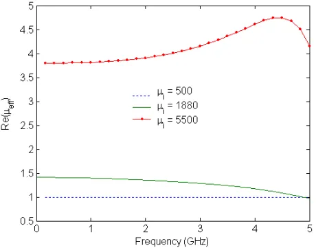
The spectrum of Re(μeff) is plotted in Fig. 6, and the spectrum of magnetic loss δm is plotted in Fig. 7 for all the above mentioned magnetization modes.
As observed from Fig. 6-Fig. 7, real part of the effective relative permeability of the metamaterial with partially magnetized inclusions has only Re(μeff) > 1, and its imaginary part can have values
Figure 6. Real part of μeff of metamaterial
versus frequencyωof wave propagated transverse to bias.
∼ 10−2÷10−1 for the case of wave propagation transverse to bias. Moreover, the value of effective relative permeability and its value range are tuned by the value of bias magnetic field.
Last results are in a good agreement with those of work [9]. The difference between the permeability values obtained here and those reported in [9] does not exceed 5%.
As seen from Figs. 2–7, the case of wave propagation in the direction of bias can “provide” us with any of possible value range of the effective relative permeability of the considered metamaterial depending on the value of bias field. At the same time, the metamaterial behaves as a conventional ferrite in the case of wave propagation transverse to bias.
5. APPLICATION HINTS
Let us define a rough range of possible applications for the considered metamaterial. In order to do that, consider a normal incidence of plane electromagnetic wave on an infinitely long metamaterial layer of thickness d. The full reflection R and transmission T coefficients are defined by [14]
R=ρ 1−e −2ikd
1−ρ2e−2ikd,
T = 1−ρ
2
1−ρ2e−2ikde− ikd
⎫ ⎪ ⎪ ⎬ ⎪ ⎪ ⎭
(31)
where ρ = μeff/eff −1
/μeff/eff + 1
is the effective Fresnel coefficient, and k = k0neff = √
effμeffω/c is the effective wavenumber,c is velocity of speed in vacuum.
As seen from Eqs. (31), if Re(μeff) < 0, then the coefficients R and T are complex. It means
that electromagnetic wave in the microwave frequency range is absorbed by the layer. That is why such a layer can be used for designing a microwave filter or microwave absorber. At the same time, as mentioned in Introductory Section, such a layer can also be used for designing the transfer element of microwave power transfer systems, [8].
As seen from Eqs. (31): limμeff→+0R =−1 and limμeff→+0T = 0. It means that if 0<Re(μeff)<1
, then electromagnetic wave in the microwave frequency range is entirely reflected by the layer changing its phase for π. It means, in turn, that the metamaterial layer can be used for designing a microwave phase inverter. At the same time, such a layer can also be used for designing the transfer element of microwave power transfer systems, [15].
As seen from Eqs. (31): limμeff→+∞R = 1 and limμeff→+∞T = 0. It means that if Re(μeff) >1
, then electromagnetic wave in the microwave frequency range is entirely reflected by the layer. It means, in turn, that the metamaterial layer can be used for designing a microwave transponder. At the same time, magnetically enhanced metamaterials (Re(μeff) > 1) can also be used for fabricating
the substrates of miniaturized microwave patch antennas [16]. Indeed, antennas printed on magnetized ferrite substrates can offer beam steering even with a single element as well as the ability of electronic tuning, [17].
6. CONCLUSION
The real part of effective relative permittivity μeff of an infinite isotropic dielectric host medium
with periodically embedded partially magnetized ferric cylindrical inclusions can have Re(μeff) < 0
or 0<Re(μeff)<1 or Re(μeff)>1, and its imaginary part can have values∼10−2÷101 depending on
the value of dc bias magnetic field. The ability to control the value of complex effective permeability by varying the value of bias magnetic field enables to use the metamaterial for designing the transfer element of microwave power transfer systems, microwave phase inverters, microwave absorbers, microwave filters, microwave transponders, substrates of miniaturized patch antennas.
ACKNOWLEDGMENT
REFERENCES
1. Beguhn, S., X. Yang, and N. X. Sun, “Wideband ferrite substrate integrated waveguide isolator using shape anisotropy,”J. Appl. Phys., Vol. 115, No. 17, 17E503, 2014.
2. Yang, S., D. Vincent, J. R. Bray, and L. Roy, “Study of a ferrite LTCC multifunctional circulator with integrated winding,”IEEE Trans. Comp., Packaging and Manufacturing Tech., Vol. 5, No. 7, 879–876, 2015.
3. Dionne, G. F. and D. E. Oates, “Tuning limitations of the voltage-controlled planar microwave ferrite resonator,”J. Appl. Phys., Vol. 111, No. 7, 07E506, 2012.
4. Nafe, A. and A. Shamim, “An integrable SIW phase shifter in a partially magnetized ferrite LTCC package,” IEEE Trans. Microwave Theory and Tech., Vol. 63, No. 7, 2264–2274, 2015.
5. Wu, J., S. Beguhn, Z. Y. Zhou, J. Lou, and N. X. Sun, “Novel C-band tunable bandpass filter with low bias magnetic fields using partially magnetized ferrites,” Proc. International IEEE MTT-S
Microwave Symposium Digest (MTT), 1–3, Montreal, Quebec, Canada, 17–22 June 2012.
6. Arabi, E., A. Syed, A. Shamim, “A planar and tunable bandpass filter on a ferrite substrate with integrated windings,” Proc. 2015 IEEE MTT-S Int. Microwave Symposium, 1–3, Phoenix, USA, 17–22 May 2015.
7. Hou, Q., Y. Y. Su, and X. P. Zhao, “A high gain patch antenna Based on PN zero permeability metamaterial,” Microw. Opt. Technol. Lett., Vol. 56, No. 5, 1065–1069, 2014.
8. Fan, Y., L. Li, S. Yu, C. Zhu, and C. Liang, “Experimental study of efficient wireless power transfer system integrating with highly sub-wavelength metamaterials,” Progress In Electromagnetics Research, Vol. 141,769–784, 2013.
9. Garcia, N. and E. V. Ponizovskaia, “Low-loss left-handed materials using metallic magnetic cylinders,” Phys. Rev. E, Vol. 71, 046611, 2005.
10. Bezougly, A. V. and V. V. Khoroshun, “Electromagnetic wave diffraction by a grating of gyrotropic circular cylinders,” Telecommunications and Radio Engineering, Vol. 57, No. 5, 1–6, 2002.
11. Rybin, O., “Unusual microwave effective properties of two-component metaferrites,” Int. J. Appl. Electromagnetics and Mech., Vol. 46, No. 3, 519–526, 2014.
12. Rybin, O., “Effective permeability tensor of partially magnetized two-component metaferrites,”
Mod. Phys. Lett. B, Vol. 28, No. 25, 1450199, 2014.
13. Simovski, C. R., P. A. Belov, A. V. Atrashchenko, and Y. S. Kivshar, “Wire metamaterials: Physics and applications,” Adv. Mat., Vol. 24, 4229–4248, 2012.
14. Ghodgaonkar, D. K., V. V. Varadan, and V. K. Varadan, “Free-space measurement of complex permittivity and complex permeability of magnetic materials at microwave frequencies,” IEEE Trans. Instrumentation and Meas., Vol. 39, No. 2, 387–394, 1990.
15. Kim, H., “Highly efficient wireless power transfer using metamaterial slab with zero refractive property,”Elec. Letts., Vol. 50, No. 16, 1158–1160, 2014.
16. Rybin, O. and S. Shulga, “Profile miniaturization and performance improvement of a rectangular patch antenna using magnetic metamaterial substrates,” Int. J. RF and Microwave Computer-Aided Engineering, Vol. 26, No. 3, 254–261, 2016.