Design of a Compact Patch Antenna Loading Periodic
Jerusalem Crosses
Siya Mi* and Yee Hui Lee
Abstract—A compact microstrip antenna loaded with periodic patterns etched in the ground plane is proposed. The etched patterns are Jerusalem crosses which look the same as one of the common electromagnetic band gap structures, uni-planar electromagnetic band gap. In this paper, the dielectric backed with etched ground plane is analysed in terms of metamaterial. The permittivity and permeability are derived from the simulated reflection and transmission coefficients. Then a patch is stacked on the metasubstrate, and the antenna is designed to operate at 2.4 GHz. The proposed antenna has a small dimension in comparison to two other published compact antennas. Compared to the conventional patch antenna, the proposed antenna achieves a 68.38% miniaturization of the patch, and a 2.84 times impedance bandwidth broadening. Furthermore, the operating frequency of the proposed antenna can be tuned over a large range of frequencies by physically adjusting the length of the surrounding slots or by voltage adjusting of the voltage controlled tunable inductive elements. The proposed antenna is fabricated and measured. The measurement results are found to agree well with the simulation ones.
1. INTRODUCTION
Microstrip antenna is widely used because of its easy fabrication and low cost. However, the microstrip antenna has some shortcomings caused by the substrate material. The high dielectric constant and small thickness of the substrate result in an antenna that has low gain and narrow bandwidth. The size of antenna is mainly determined by the frequency of operation and properties of the substrate material. Taking the conventional patch antenna as an example, the length of the patch is about half of the guided wavelength. In recent years, metamaterials have received considerable attention. This is due to their special properties, which have not yet been found in nature. Metamaterials are able to improve antenna performances through the control of electromagnetic wave propagation and to address some of the shortcomings of the conventional microstrip antenna.
The metamaterial in this paper contains a uni-planar periodic structure. One of the most common metamaterials is electromagnetic band gap (EBG). It can prevent the electromagnetic wave propagation over a certain frequency range; therefore, it is often arranged around the antenna in such a way as to reduce the back lobe. EBG can also decrease the coupling between antennas in an antenna array. This can be achieved by laying EBG structures between the antenna elements of the array [1]. Frequency selective surface (FSS) is another one of the commonly used metamaterials. Working as a PEC in the operating frequency and presenting the bandpass features out of the operating frequency, FSS is able to reduce the backward scattering [2–4]. Nowadays, metamaterials are more and more frequently used in the microstrip antenna designs to replace the traditional substrate materials [5–7]. The metasubstrate can be used to improve the operating performance of an antenna, such as its radiation efficiency, gain, and impedance bandwidth.
Received 22 February 2016, Accepted 27 March 2016, Scheduled 9 April 2016
* Corresponding author: Siya Mi ([email protected]).
The miniaturization of antennas, similarly, can be achieved by using metamaterials. In [8], by placing a complementary split-ring resonators (CSSR) between the patch and the ground of the antenna, the size of the patch is significantly decreased. However, this metasubstrate has two layers, making it difficult to fabricate and doubling the thickness of this antenna. The radiation efficiency is reduced, and it is even worse that this design makes the already narrow bandwidth even narrower. In [9], a microstrip antenna is miniaturized by loading a single-layer metamaterial in which four U-shaped structures are etched under the patch. This design improves both the radiation efficiency and the bandwidth, but it is difficult to fabricate because of the vertical vias. In [10], a simple single-layer patch antenna with embedded meander-line (EML) loading is proposed. This design is easy to fabricate, can reduce the patch size by about 35%, and broadens the bandwidth by 1.85 times compared to the conventional patch antenna. However, the etched EMLs allow energy leakage to the back, and thus, reducing the main lobe and gain. In order to increase the gain, a metal plane reflector is placed beneath and parallel to the antenna ground plane. However, in order for the reflector to be effective, the distance between the reflector and the antenna ground has to be as large as 5 mm (0.058λ0). Therefore, even though the patch size is reduced, the overall demission of the antenna remains large, because the total thickness of the antenna is 4.2 times of the original.
In this paper, we propose to etch periodic Jerusalem crosses in the antenna ground plane. The Jerusalem cross is one of the most common patterns which are applied in metamaterial. The Jerusalem crosses can be arranged periodically to form an absorber. In [11], a multi-band absorption is effectively obtained by assembling the Jerusalem crosses. The achieved absorption rate is 96.2%–99.5%. In [12], the Jerusalem cross is used to design a Terahertz absorber with a near-perfect absorption. This absorber can be applied in medical imaging and communication systems. In our design, the etched Jerusalem cross is used as a metasubstrate. It can be used to reduce the size of an antenna and to improve the bandwidth. Besides performance improvement, this structure is also simple to implement and easy to fabricate. For fabrication purpose, a low cost FR4 is chosen as the substrate. Although the loss tangent of FR4 is high, the radiation efficiency is improved significantly compared to the conventional patch antenna. The improvement of maximum realized gain is small, because of energy leakage through the defects in the ground plane as explained in [10].
2. METASUBSTRATE DESIGN
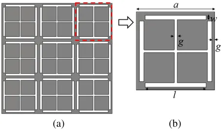
The metasubstrate is constituted by a piece of dielectric backed with a ground plane etched with a 3 by 3 Jerusalem cross array. The patterned ground plane and the unit cell etched with a Jerusalem cross is shown in Fig. 1. Each unit cell contains four etched patches in the centre in the form of a cross, and four etched arms attached at the end. The parameter values of the unit cell are as follows, a= 7 mm, l= 5.5 mm,w= 0.4 mm, and g= 0.25 mm. In this design, the dielectric parameter of the FR4, withϵr of 4.3 and loss tangent (tanδ) of 0.025. The thickness of the substrate is 0.8 mm.
If the electrically small patterned structures are arranged in the material periodically, the
(a) (b)
metamaterial can be taken as a uniform dielectric with a certain permittivity and permeability. The effective permittivity will get smaller because of the absence of metal due to the etched pattern in the ground plane. The permittivity and permeability of the metamaterial can be derived from the transmission and reflection coefficients [13, 14]. A microstrip line on top of the metasubstrate is simulated in order to examine the properties of the metasubstrate. This structure is simulated using CST Microwave Studio (a 3D EM simulation software), and the transmission and reflection coefficients are acquired. The impedance Z and refractive index n can be derived from the transmission and reflection coefficients given by Eqs. (1)–(3).
Z = ±
√
(1 +S11)2−S212
(1−S11)2−S212 (1)
n = 1 k0d
{
Im[ln(eink0d)] + 2mπ−jRe[ln(eink0d)] }
(2)
eink0d = S21
1−S11 Z−1 Z+ 1
(3)
wherek0 is the wave number in free space, andk0 = 2πf /c. dis the transmission distance between two ports; in other words, it is the length of the dielectric.
In Eq. (1), the sign of Z should be determined carefully to ensure Re(Z) ≥ 0 and Im(n) ≥ 0, or equivalently, |eink0d| ≤ 1. In Eq. (2), m is an integer related to the real part of the refractive index,
which can be determined exactly by the method in [15]. The effective permittivity and permeability of the metasubstrate can be then calculated as Eq. (4) and Eq. (5).
ϵmeta = n
Z (4)
µmeta = nZ (5)
The calculated permittivity is shown in Fig. 2(a). From 1 GHz to 4 GHz, the real part of ϵmeta is greater than 0, and it is almost below the original permittivity ϵr of the FR4 (ϵr = 4.3) except at around 1.45 GHz. The low permittivity of the metasubstrate is due to the leakage of electric field from the defects in the ground plane. This effectively reduces the permittivity of the substrate. Note that the effective ϵof the metasubstrate varies with frequency. The permeability of the substrate is plotted in Fig. 2(b). From 1 GHz to 3.0 GHz, the real part ofµmeta is bigger than 1 (the permeability of FR4 and air), and it falls to 0 when the frequency is larger than about 3.0 GHz. Above 3.0 GHz, the permeability being blow 0 performs as a negative permeability material. The imaginary parts of ϵmeta and µmeta indicate that there is leakage loss of the gap in the ground.
3. ANTENNA DESIGN
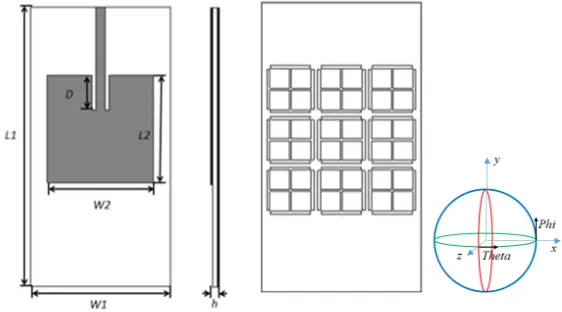
The patch of the antenna is designed as a simple square patch. The length of the patch is the half of the wavelength in metasubstrate. This is calculated using Eq. (6) [16]. An antenna operating at 2.4 GHz will be designed. In Fig. 2, the permittivity and permeability of the metasubstrate at 2.4 GHz can be determined to be 1.9 and 14.4, respectively. The imaginary parts are ignored, since they are very small, which indicates that the loss is negligible. Even through the permittivity of the metasubstrate is less than 4.3, the length of the patch is reduced due to the dominant increase in the permeability of the metasubstrate, µeff. The practical length of the patch should be longer because of the fringing
effect. Based on the theory and simulation, the length of the patch is determined to be 16.7 mm for an operating frequency of 2.4 GHz.
L= c
2πf√ϵeffµeff
(6)
(a) (b)
Figure 2. (a) The permittivity of the metasubstrate. (b) The permeability of the metasubstrate.
Figure 3. The illustration of microstrip antenna.
regardless of the size of the ground plane. Therefore, the ground plane size is kept at 22 mm×40 mm. On the top side, a 50 ohm microstrip insert feed line is used to feed the patch antenna and also to achieve the impedance matching. The insert depth is calculated to be 9 mm. The top and bottom views of the proposed antenna is as shown in Fig. 3.
4. RESULTS AND DISCUSSION 4.1. Simulated Results
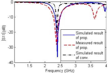
The proposed antenna is simulated by CST studio. A conventional patch antenna, which also operates at 2.4 GHz and uses the same FR4 PCB as the substrate, is simulated for comparison purposes. The reflection coefficients of both simulated antennas are shown in Fig. 4. The solid line and dash dot line are the simulated reflection coefficient of the antennas using metasubstrate and conventional dielectric, respectively. The −10 dB impedance bandwidth of the antenna using metasubstrate is about 7.1%, while the bandwidth of the conventional patch antenna is only 2.5%. The quality factor is proportional to the permittivity of the substrate and is inversely proportional to the permeability as shown in Eq. (7).
Q= πwp
√ϵ eff
2Grhη0√µeff
(7)
whereGr is the radiation conductance andη0 the electromagnetic wave impedance in free space. Thus, by decreasingϵeff and increasingµeff, the Q factor of the antenna becomes smaller, and the bandwidth
Figure 4. The simulated and measured return loss.
Table 1. Comparison of the antenna using metasubstrate and the conventional patch antenna.
Patch Size (mm2) Bandwidth Radiation Efficiency
Metasubstrate Antenna 16.7×16.7 7.1% 88.5%
Conventional Antenna 29.7×29.7 2.5% 46.3%
(a) (b)
Figure 5. The simulated and measured radiation pattern. (a) E-plane. (b) H-plane.
The radiation patterns of the proposed antenna are plotted in Fig. 5. From the radiation patterns, it can be seen that some energy leakage to the back through the patterns etched in the ground plane is observed in the form of an increasing in the back lobe of the antenna. The directivity of this antenna gets smaller, and it looks like an omnidirectional antenna. The dimension and radiation performance of the proposed antenna and conventional patch antenna are listed in Table 1.
In Table 1, the radiation efficiency is high, at 88.5%, while the radiation efficiency of the conventional patch antenna is only 46.3% because of the high tangent loss of the FR4 dielectric substrate. The radiation efficiency takes into consideration the reflection, conduction, and dielectric losses. The efficiency is defined as the ratio of the power radiating out to the total delivered power [16], so the efficiency is in Eq. (8).
e= Rr Rr+RL
(8)
(a) (b)
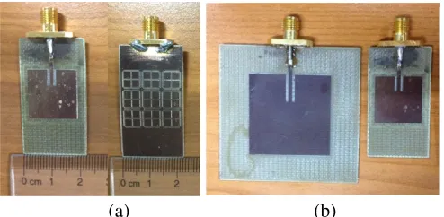
Figure 6. The photos of microstrip antenna. (a) The top view and back view of proposed antenna. (b) The proposed antenna vs. the conventional patch antenna.
Table 2. Comparison of the antenna using various metamaterials.
Antenna (Reference) Unite Cell of Metamaterial Antenan Size
Proposed UC-EBG 0.17λ0×0.32λ0×0.006λ0
[9] Inverted U shape 0.17λ0×0.32λ0×0.030λ0 [10] Embedded meander line 0.70λ0×0.89λ0×0.017λ0
4.2. Fabrication and Measured Results
The antenna with metasubstrate is fabricated. Without any vertical vias and connectors. This one-layer antenna is very easy to fabricate and can be done using the common PCB milling machine. Photos of the fabricated antenna are shown in Fig. 6(a). In order to visualise the significant difference in the dimensions of the antenna and the proposed metasubstrate patch antenna, they, operating at 2.4 GHz, are placed together and compared in Fig. 6(b). It is easy to see that the proposed antenna is able to achieves a significant reduction in antenna size. The proposed compact antenna is also compared with some of the small size antennas introduced in Section 1. Their dimensions are listed in Table 2. Compared with the conventional patch antenna and the two published small size antennas, the proposed antenna has the smallest dimension.
The compact antenna is measured in an anechoic chamber. The measured S-parameter and radiation pattern are plotted and compared with the simulated ones in Fig. 4 and Fig. 5, respectively. The measured and simulated results agree well with each other.
4.3. Frequency Tuning
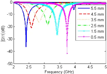
The flexibility of operating frequency tuning is one of the most important issues to determine the performance of an antenna [17]. In our proposed design, the resonance frequency can be tuned conveniently by changing the arm slots of length, l, as shown in Fig. 1(b). By changing the arm slot length, l, the effective permittivity and permeability of the metasubstrate can be varied. It is a common practice to adjust the size or the frequency of operation of the antenna by changing the effective permittivity or permeability of the substrate.
Figure 7. The dependence of reflection coefficients on parameter l.
(a) (b)
Figure 8. The radiation patterns with varied l. (a)E-plane. (b) H-plane.
(a) (b)
Figure 9. The equivalent circuit of the tunable antenna. (a) the pattern in the ground plane. (b) one unit cell with diodes.
for the back lobe. However, this can be expected as the back lobe is determined by the amount of leakage through the ground plane. Therefore, the smallest arm length, l, results in the smallest back lobe and vice versa.
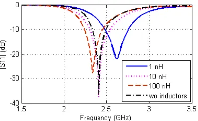
However, the physical dimension of the slot can only be adjusted through re-fabrication. Therefore, we explore the possibility of using lump components for the tuning of the operation frequency of the antenna. Note that this technique is also employed in the implementation of the reconfigurable frequency selective surfaces [18].
Figure 10. The simulated result of the tunable antenna.
(a) (b)
Figure 11. The radiation patterns with varied inductance. (a) E-plane. (b)H-plane.
When the tunable inductor is adjusted from 100 nH to 1 nH, the operating frequency of the antenna can be tuned from 2.33 GHz to 2.62 GHz. Even through the tunable inductors can vary the equivalent inductance, its effect on the electromagnetic wave propagation proprieties of the structure in the ground is not as significant as the physical variation in the length of the arm slot. Thus, the frequency range tuned by the lumped elements is not as significant as the frequency range tuned by the change in physical length of the arms. The simulated results are as shown in Fig. 10. Note that the impedance match is kept well. In Fig. 11, the radiation patterns of the antenna with tunable inductors are plotted. When the inductance equals 1 nH and 100 nH, the radiation patterns are almost the same with no variation in the size of the back lobe at the corresponding resonant frequency. That is because when the inductance is tuned, the physical shape and dimension of this antenna and slots remains unchanged.
5. CONCLUSION
REFERENCES
1. Yang, F. and Y. Rahmat-Samii, “Microstrip antennas integrated with electromagnetic band-gap (EBG) structures: A low mutual coupling design for array applications” IEEE Transactions on Antennas and Propagation, Vol. 51, No. 10, 2936–2946, 2003.
2. Li, H., B. Z. Wang, G. Zheng, and W. Shao, “A reflectarray antenna backed on FSS for low RCS and high radiation performances,” Progress In Electromagnetics Research C, Vol. 15, 145–155, 2010.
3. Jia, Y., Y. Liu, H. Wang, K. Li, and S. Gong, “Low-RCS high-gain and wideband mushroom antenna,”IEEE Antennas Wireless Propagation Letter , Vol. 14, 277–280, 2015.
4. Kim, S.-H., T. T. Nguyen, and J.-H. Jang, “Reflection characteristics of 1-D EBG ground plane and its application to a planar dipole antenna,” Progress In Electronagnetics Research, Vol. 120, 51–66, 2011.
5. Xu, H.-X., G.-H. Wang, and M.-Q. Qi, “ A miniaturized triple-band metamaterial antenna with radiation pattern selectivity and polarization diversity,” Progress In Electromagnetics Research, Vol. 137, 275–292, 2013.
6. Wu, B.-I., W. Wang, J. Pacheco, X. Chen, T. Crzegorczyk, and J. A. Kong, “A study of using metamaterials as antenna substrate to enhance gain,” Progress In Electromagnetics Research, Vol. 15, 295–328, 2005.
7. Rahimi, M., F. B. Zarrabi, R. Ahmadian, Z. Mansouri, and A. Keshtkar, “Miniaturization of antenna for wireless application with difference metamaterial structures,” Progress In Electromagnetics Research, Vol. 145, 19–29, 2014.
8. Ouedraogo, R. O., E. J. Rothwell, A. R. Diaz, K. Fuchi, and A. Temme, “ Miniaturization of patch antenna using a metamaterial-inspired technique,” IEEE Transactions on Antenna and Propagation, Vol. 60, No. 5, 2175–2182, 2012.
9. Saghanezhad, S. A. H. and Z. Atlasbaf, “ Miniaturized dual-band CPW-fed antennas loaded with U-shaped metamaterials,”IEEE Antennas Wireless Propagation Letter, Vol. 14, 658–661, 2015. 10. Yang, X. M., Q. H. Sun, Y. Jing, Q. Cheng, X. Y. Zhou, H. W. Kong, and T. J. Cui, “Increasing the
bandwidth of microstrip patch antenna by loading compact artificial magneto-dielectrics,” IEEE Transactions on Antenna and Propagation, Vol. 59, No. 2, 373–378, 2011.
11. Wang, G. D., M. H. Liu, X. W. Hu, L. H. Kong, L. L. Cheng, and Z. Q. Chen, “Multi-band microwave metamaterial absorber based on coplanar Jerusalem crosses,”Chinese Physics B, Vol. 23, No. 1, 017802, 2013.
12. Arezoomand, A. S., F. B. Zarrabi, S. Heydari, and N. P. Gandji, “Independent polarization and multi-band THz absorber base on Jerusalem cross,” Optics Communications, Vol. 352, 121–126, 2015.
13. Smith, D. R., S. Schultz, P. Markos, and C. M. Soukoulis, “Determination of effective permittivity and permeability of metamaterials from reflection and transmission coefficients,”Physical Review B, Vol. 65, No. 19, 195104, 2002.
14. Hasar, U. C., J. J. Barroso, C. Sabah, I. Y. Ozbek, Y. Kaya, D. Dal, and T. Aydin, “Retrieval of effective electromagnetics parameters of isotropic metamaterials using reference-plane invariant expressions,”Progress In Electromagnetics Research, Vol. 132, 425–441, 2012.
15. Szab, Z., G. Park, R. Hedge, and E. Li, “A unique extraction of metamaterial parameters based on Kramers-Kronig relationship,”IEEE Transactions on Microwave Theory and Techniques, Vol. 58, No. 10, 2646–2653, 2010.
16. Balanis, C. A.,Antenna Theory: Analysis and Design, John Wiley and Sons, 1997.
17. Cai, T., G.-M. Wang, and J.-G. Liang, “Analysis and design of novel 2-d transmission line metamaterial and its application to compact dualband antenna,” IEEE Antennas Wireless Propagation Letter, Vol. 13, 555–558, 2014.