Scholarship@Western
Scholarship@Western
Electronic Thesis and Dissertation Repository
4-14-2016 12:00 AM
Arthrokinematics of the Distal Radioulnar Joint in the Normal
Arthrokinematics of the Distal Radioulnar Joint in the Normal
Wrist and Following Distal Radius Malunion
Wrist and Following Distal Radius Malunion
Braden M. Gammon
The University of Western Ontario
Supervisor Dr. Graham King
The University of Western Ontario Joint Supervisor Dr. James Johnson
The University of Western Ontario
Graduate Program in Medical Biophysics
A thesis submitted in partial fulfillment of the requirements for the degree in Master of Science © Braden M. Gammon 2016
Follow this and additional works at: https://ir.lib.uwo.ca/etd
Part of the Medical Biophysics Commons
Recommended Citation Recommended Citation
Gammon, Braden M., "Arthrokinematics of the Distal Radioulnar Joint in the Normal Wrist and Following Distal Radius Malunion" (2016). Electronic Thesis and Dissertation Repository. 3713.
https://ir.lib.uwo.ca/etd/3713
This Dissertation/Thesis is brought to you for free and open access by Scholarship@Western. It has been accepted for inclusion in Electronic Thesis and Dissertation Repository by an authorized administrator of
Contact patterns in the distal radioulnar joint (DRUJ) are not well understood for normal anatomy or with distal radius deformity. This thesis presents three studies which investigate the arthrokinematics of the DRUJ for these conditions. The first study compared casting and Tekscan, two standard methods for contact measurement, with a novel technique of
proximity mapping termed Inter-cartilage Distance (ICD). The relative benefits, limitations and role for ICD in DRUJ contact assessment were examined and discussed. The second study used ICD to characterize contact patterns in the native DRUJ. Contact was found to be maximal in 10° of supination and the contact centroid moved volar and proximal with
supination. The third and final study evaluated the effect of dorsal angulation deformity on DRUJ arthrokinematics. The contact centroid moved volarly, while simulated triangular fibrocartilage complex (TFCC) rupture reduced DRUJ contact area and caused the centroid position to become more variable in its pathway.
ii
Co-Authorship Statement
Chapter OneSole author – Braden Gammon
Manuscript Review – Graham King, Jim Johnson
Chapter Two
Study Design – Braden Gammon, Emily Lalone, Graham King, Jim Johnson Specimen Preparation – Braden Gammon
Data Collection – Braden Gammon, Mark Welsh
Data Analysis – Braden Gammon, Emily Lalone, Ryan Willing Statistical Analysis – Braden Gammon
Manuscript Preparation – Braden Gammon
Manuscript Review – Emily Lalone, Graham King, Jim Johnson
Chapter Three
Study Design – Braden Gammon, Emily Lalone, Graham King, Jim Johnson Specimen Preparation – Braden Gammon, Masao Nishiwaki
Data Collection – Braden Gammon, Mark Welsh, Masao Nishiwaki Data Analysis – Braden Gammon, Emily Lalone, Ryan Willing Statistical Analysis – Braden Gammon
Manuscript Preparation – Braden Gammon
Manuscript Review – Emily Lalone, Graham King, Jim Johnson
A version of this manuscript will be submitted to the Journal of Hand Surgery (American) entitled: In Vitro Arthrokinematics of the Intact DRUJ
Authors: Gammon B, Lalone E, Willing R, Nishiwaki M, Johnson J, King GJW
Chapter Four
Study Design – Braden Gammon, Emily Lalone, Graham King, Jim Johnson Specimen Preparation – Braden Gammon, Masao Nishiwaki
Data Collection – Braden Gammon, Mark Welsh, Masao Nishiwaki Data Analysis – Braden Gammon, Emily Lalone, Ryan Willing Statistical Analysis – Braden Gammon
Manuscript Preparation – Braden Gammon
Manuscript Review – Emily Lalone, Graham King, Jim Johnson
A version of this manuscript will be submitted to the Journal of Hand Surgery (American) entitled: The effect of Dorsal Angulation Deformities on In Vitro Arthrokinematics of the DRUJ
Authors: Gammon B, Lalone E, Willing R, Nishiwaki M, Johnson J, King GJW
Chapter Five
Sole author – Braden Gammon
iii
Acknowledgments
It is with a deep sense of admiration and gratitude that I acknowledge the support of my supervisors, Dr. Graham King and Dr. Jim Johnson. Together they have created a space and vehicle for students from all over the globe to gather and hone their skills in the field of biomechanical research. It is this type of environment that facilitates the cross-pollination of techniques and ideas, and breeds new thought leaders and researchers. I am humbled to have worked with some of the best in this field, and am grateful for the opportunities this has afforded me.
I will fondly remember my two lab testing partners, Mark Welsh and Masao
Nishiwaki. Both are immensely talented individuals who co-developed the novel wrist simulator this testing took place upon. I am grateful to Masao for exposing me to the nuances of specimen preparation, wrist anatomy and of course, Japanese culture. Both Mark and I would like to think we lightened the otherwise lengthy testing days he organized with our music, companionship and revelry.
I am indebted to Emily Lalone, who tirelessly introduced me to the budding scientific realm of Arthrokinematics. Her energy and unfailingly upbeat attitude was motivating, particularly when concepts and data analysis techniques seemed daunting. I have an entirely new appreciation for how kinematics and 3-D modeling can come together to generate great science when the right person is steering the ship. I also owe thanks to Ryan Willing, who developed key programs for our data analysis which added a layer of completeness and polish to the work.
iv
Dedication
This manuscript is dedicated to my beautiful, loving, patient wife Jessica and our sons Liam and Kai, who are the pride and centre of our lives. I have “refined” this thesis over the course of 3+ years and it has diverted my attention on many evenings and weekends.
Throughout this time they have remained sympathetic, encouraging and supportive. Its completion is a combined achievement that we will all celebrate with pride.
I would also like to pay a sincere tribute to the late Dr. Jim Roth. I was fortunate to train under Dr. Roth during one of the final rotations he supervised at the Roth | McFarlane Hand and Upper Limb Center. His teaching was crafted through experience from a
v
Table of Contents
Abstract ... i
Co-Authorship Statement... ii
Acknowledgments... iii
Dedication ... iv
Table of Contents ... v
List of Figures ... viii
List of Appendices ... xi
Chapter 1 ... 1
1 General Introduction ... 1
1.1 Bony and Soft Tissue Anatomy of the DRUJ ... 1
1.2 Stabilizers of the DRUJ ... 10
1.3 DRUJ and Forearm Biomechanics... 13
1.4 Distal Radius Malunion and its Influence on the DRUJ ... 15
1.5 Joint Contact at the DRUJ in Normal and Malunited Conditions ... 17
1.6 Methods for Assessing Joint Contact ... 18
1.6.1 Direct Methods... 18
1.6.2 Indirect Methods ... 19
1.7 Rationale ... 22
1.8 Objectives and Hypotheses ... 23
1.9 Thesis Overview ... 24
1.10 References ... 25
2 Comparison of Inter-cartilage Distance as a Method for Assessing Arthrokinematics of the Distal Radioulnar Joint ... 37
2.1 Overview ... 37
vi
2.3 Methods... 39
2.3.1 Experimental Protocol – Specimen Preparation ... 39
2.3.2 Experimental Protocol – Non-invasive contact measurement ... 42
2.3.3 Experimental Protocol – Invasive contact measurement ... 42
2.3.4 Measurement of DRUJ Contact Area – Casting ... 46
2.3.5 Measurement of DRUJ Contact Area – Inter-cartilage Distance Algorithm (ICD) ... 49
2.4 Results ... 51
2.5 Discussion ... 54
2.6 References ... 60
3 Arthrokinematics of the distal radioulnar joint measured using Inter-cartilage Distance in an in vitro model ... 63
3.1 Overview ... 63
3.2 Introduction ... 63
3.3 Materials and Methods ... 64
3.3.1 Specimen Preparation ... 64
3.3.2 Simulation of Motion ... 65
3.3.3 Motion Tracking and Kinematic Data Acquisition ... 65
3.3.4 ICD Measurement Technique ... 66
3.3.5 Data Analysis ... 70
3.4 Results ... 71
3.5 Discussion ... 75
3.6 References ... 78
4 The effect of dorsal angulation deformities on arthrokinematics of the DRUJ measured using Inter-cartilage Distance ... 82
4.1 Introduction ... 82
vii
4.2.1 Specimen Preparation ... 83
4.2.2 Simulation of Motion ... 84
4.2.3 Motion Tracking and Kinematic Data Acquisition ... 84
4.2.4 Simulation of Distal Radius Deformity ... 85
4.2.5 Testing Procedure ... 87
4.2.6 ICD Measurement Technique ... 88
4.2.7 Data Analysis ... 90
4.3 Results ... 90
4.4 Discussion ... 94
4.5 References ... 98
5 SGPS General Discussion, Conclusions and Future Work ... 102
5.1 Overview ... 102
5.2 Objectives and Hypotheses ... 102
5.3 Comparison of Inter-cartilage Distance as a method for assessing arthrokinematics of the DRUJ ... 102
5.4 Arthrokinematics of the DRUJ measured using Inter-cartilage Distance (ICD) in an in vitro model ... 103
5.5 The effect of dorsal angulation deformities on arthrokinematics of the DRUJ measured using Inter-cartilage Distance (ICD) ... 104
5.6 General Discussion ... 105
5.7 Future Directions ... 107
viii
List of Figures
Figure 1.1: Bony anatomy of the forearm ... 1
Figure 1.2: The Triangular Fibrocartilage Complex ... 2
Figure 1.3: Pronator Quadratus (PQ) ... 3
Figure 1.4: Extensor Tendons ... 3
Figure 1.5: Interosseous Membrane (IOM) ... 4
Figure 1.6: An axial representation of the DRUJ.. ... 4
Figure 1.7: Osseous and articular anatomy of the distal radius and ulna ... 5
Figure 1.8: Radius of curvature and cartilaginous coverage of the ulnar head and sigmoid notch ... 6
Figure 1.9: Cartilage distribution within the sigmoid notch ... 6
Figure 1.10: Sagittal plane morphology of the sigmoid notch... 7
Figure 1.11: Coronal plane morphology of the DRUJ ... 8
Figure 1.12: Bony anatomy of the ulna. ... 9
Figure 1.13: Bony anatomy of the radius... 10
Figure 1.14: Superficial fibers and deep fibers of the radioulnar ligaments ... 11
Figure 1.15: Centre of rotation of the forearm ... 14
Figure 1.16: Measurement parameters for the distal radial articular surface ... 16
Figure 1.17: A DRUJ casting illuminated on a lightbox ... 18
Figure 1.18: Inter-cartilage Distance algorithm for proximity mapping ... 21
ix
Figure 2.1 Custom forearm testing apparatus ... 40
Figure 2.2 The pulley suspension system of the apparatus ... 41
Figure 2.3 Forearm specimen mounted in the custom positioning apparatus ... 43
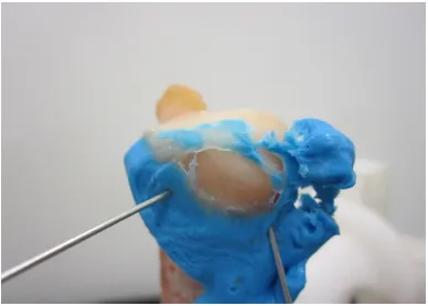
Figure 2.4 Casting material inside the distal radioulnar joint. ... 44
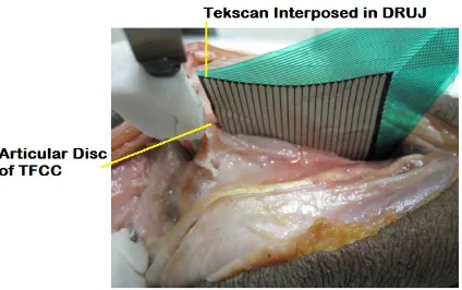
Figure 2.5 The Tekscan® sensor inserted in the DRUJ ... 45
Figure 2.6 The radius and ulna with mounted infrared optical marker triads ... 45
Figure 2.7 The distal radius with spherical nylon fiducial markers. ... 46
Figure 2.8 The casting of the DRUJ affixed to the ulnar head with pins ... 47
Figure 2.9 3-D point cloud designated as the contact patch. ... 48
Figure 2.10 The digitized point cloud superimposed on the registered ulna model. ... 49
Figure 2.11 Registered 3-D bone models depicted in Paraview ... 50
Figure 2.12 The output for Inter-cartilage Distance, Casting and Tekscan ... 52
Figure 2.13 DRUJ contact area in the loaded condition with the forearm 45° pronated ... 53
Figure 2.14 DRUJ contact area in the loaded condition with the forearm 80° pronated ... 53
Figure 2.15 DRUJ contact area in the unloaded condition with the forearm 80° pronated ... 54
Figure 2.16 The radius and ulna models are re-assembled during the ICD algorithm ... 57
Figure 2.17 A DRUJ casting and its corresponding ICD contact map ... 59
Figure 3.1 A cadaveric specimen mounted in a custom forearm motion simulator ... 66
Figure 3.2 The denuded ulna of a specimen ... 67
x
Figure 3.4 The sigmoid notch of the distal radius with directionality as depicted by
anatomical axes shown ... 70
Figure 3.5 The sigmoid notch is viewed en face, with a typical contact map output shown.. 72
Figure 3.6 Contact area measurement for the distal radioulnar joint ... 73
Figure 3.7 The mean position of the contact centroid on the face of the sigmoid notch ... 74
Figure 4.1 A cadaveric specimen mounted in a custom forearm motion simulator. ... 85
Figure 4.2 The custom adjustable implant is inset into the distal radius ... 86
Figure 4.3 Depicting the four different deformity conditions... 87
Figure 4.4 A photo of the sectioned TFCC ... 88
Figure 4.5 A flowchart detailing the stages of post-experiment data processing ... 89
Figure 4.6 Depicting the DRUJ contact area for the normal condition (SW) and with an increasing degree of dorsal angulation deformity (DA10/20/30) ... 91
Figure 4.7 Depicting the DRUJ contact area after TFCC sectioning, for the normal condition (SW) and with an increasing degree of dorsal angulation deformity (DA10/20/30) ... 91
Figure 4.8 The position of the contact centroid on the face of the sigmoid notch during forearm rotation. ... 93
xi
List of Appendices
Appendix 1: Glossary of Medical Terms ... 111
Appendix 2: Contact Maps for Specimens 1-8 ... 118
Appendix 2.1 10-07029L Intact Active Supination ... 118
Appendix 2.2 10-07029L Intact Passive Supination... 118
Appendix 2.3 10-07029L SW1 Active Supination ... 119
Appendix 2.4 10-07029L Dorsal Angulation 10° Active Supination ... 119
Appendix 2.5 10-07029L Dorsal Angulation 20° Active Supination ... 119
Appendix 2.6 10-07029L Dorsal Angulation 30° Active Supination ... 120
Appendix 2.7 10-07029L TFCC Dorsal Angulation 10° Active Supination ... 120
Appendix 2.8 10-07029L TFCC Dorsal Angulation 20° Active Supination ... 120
Appendix 2.9 10-07029L TFCC Dorsal Angulation 30° Active Supination ... 121
Appendix 2.10 11-03057L Intact Active Supination ... 121
Appendix 2.11 11-03057L Intact Passive Supination... 121
Appendix 2.12 11-03057L SW1 Active Supination ... 122
Appendix 2.13 11-03057L Dorsal Angulation 10° Active Supination ... 122
Appendix 2.14 11-03057L Dorsal Angulation 20° Active Supination ... 122
Appendix 2.15 11-03057L Dorsal Angulation 30° Active Supination ... 123
Appendix 2.16 11-03057L TFCC SW1 Active Supination ... 123
xii
Appendix 2.18 11-03057L TFCC Dorsal Angulation 20° Active Supination ... 124
Appendix 2.19 11-03057L TFCC Dorsal Angulation 30° Active Supination ... 124
Appendix 2.20 11-10052L Intact Active Supination ... 125
Appendix 2.21 11-10052L Intact Passive Supination... 125
Appendix 2.22 11-10052L SW1 Active Supination ... 126
Appendix 2.23 11-10052L Dorsal Angulation 10° Active Supination ... 126
Appendix 2.24 11-10052L Dorsal Angulation 20° Active Supination ... 126
Appendix 2.25 11-10052L Dorsal Angulation 30° Active Supination ... 127
Appendix 2.26 11-10052L TFCC Dorsal Angulation 10° Active Supination ... 127
Appendix 2.27 11-10052L TFCC Dorsal Angulation 20° Active Supination ... 127
Appendix 2.28 11-10052L TFCC Dorsal Angulation 30° Active Supination ... 128
Appendix 2.29 11-12061L Intact Active Supination ... 128
Appendix 2.30 11-12061L Intact Passive Supination... 128
Appendix 2.31 11-12061L SW1 Active Supination ... 129
Appendix 2.32 11-12061L Dorsal Angulation 10° Active Supination ... 129
Appendix 2.33 11-12061L Dorsal Angulation 20° Active Supination ... 129
Appendix 2.34 11-12061L Dorsal Angulation 30° Active Supination ... 130
Appendix 2.35 11-12061L TFCC SW1 Active Supination ... 130
Appendix 2.36 11-12061L TFCC Dorsal Angulation 10° Active Supination ... 130
xiii
Appendix 2.38 11-12061L TFCC Dorsal Angulation 30° Active Supination ... 131
Appendix 2.39 12-01004L Intact Active Supination ... 131
Appendix 2.40 12-01004L Intact Passive Supination... 132
Appendix 2.41 12-01004L SW1 Active Supination ... 132
Appendix 2.42 12-01004L Dorsal Angulation 10° Active Supination ... 132
Appendix 2.43 12-01004L Dorsal Angulation 20° Active Supination ... 133
Appendix 2.44 12-01004L Dorsal Angulation 30° Active Supination ... 133
Appendix 2.45 12-01004L TFCC SW1 Active Supination ... 133
Appendix 2.46 12-01004L TFCC Dorsal Angulation 10° Active Supination ... 134
Appendix 2.47 12-01004L TFCC Dorsal Angulation 20° Active Supination ... 134
Appendix 2.48 12-01004L TFCC Dorsal Angulation 30° Active Supination ... 134
Appendix 2.49 12-01056L Intact Active Supination ... 135
Appendix 2.50 12-01056L Intact Passive Supination... 135
Appendix 2.51 12-01056L SW1 Active Supination ... 135
Appendix 2.52 12-01056L Dorsal Angulation 10° Active Supination ... 136
Appendix 2.53 12-01056L Dorsal Angulation 20° Active Supination ... 136
Appendix 2.54 12-01056L Dorsal Angulation 30° Active Supination ... 136
Appendix 2.55 12-01056L TFCC SW1 Active Supination ... 137
Appendix 2.56 12-01056L TFCC Dorsal Angulation 10° Active Supination ... 137
xiv
Appendix 2.58 12-01056L TFCC Dorsal Angulation 30° Active Supination ... 138
Appendix 2.59 12-02067L Intact Active Supination ... 138
Appendix 2.60 12-02067L Intact Passive Supination... 138
Appendix 2.61 12-02067L SW1 Active Supination ... 139
Appendix 2.62 12-02067L Dorsal Angulation 10° Active Supination ... 139
Appendix 2.63 12-02067L Dorsal Angulation 20° Active Supination ... 139
Appendix 2.64 12-02067L Dorsal Angulation 30° Active Supination ... 140
Appendix 2.65 12-02067L TFCC SW1 Active Supination ... 140
Appendix 2.66 12-02067L TFCC Dorsal Angulation 10° Active Supination ... 140
Appendix 2.67 12-02067L TFCC Dorsal Angulation 20° Active Supination ... 141
Appendix 2.68 12-02067L TFCC Dorsal Angulation 30° Active Supination ... 141
Appendix 2.69 12-09013L Intact Active Supination ... 141
Appendix 2.70 12-09013L Intact Passive Supination... 142
Appendix 2.71 12-09013L SW1 Active Supination ... 142
Appendix 2.72 12-09013L Dorsal Angulation 10° Active Supination ... 142
Appendix 2.73 12-09013L Dorsal Angulation 20° Active Supination ... 143
Appendix 2.74 12-09013L Dorsal Angulation 30° Active Supination ... 143
Appendix 2.75 12-09013L TFCC SW1 Active Supination ... 143
Appendix 2.76 12-09013L TFCC Dorsal Angulation 10° Active Supination ... 144
xv
Chapter 1
1
General Introduction
This thesis focuses on the use of Inter-cartilage Distance to measure arthrokinematics of the distal radioulnar joint (DRUJ). Contact relationships between the radius and ulna at the DRUJ are evaluated in both normal conditions, and in the setting of distal radius malunion. This chapter reviews the anatomy and biomechanics of the DRUJ. Methods for assessing articular contact and the effect of malunited distal radius fractures on the DRUJ are discussed, followed by a summary of the study rationale, objectives and hypotheses.
1.1
Bony and Soft Tissue Anatomy of the DRUJ
Two bones, the radius and ulna, constitute the bony architecture of the forearm. They articulate at the proximal (PRUJ) and distal (DRUJ) radioulnar joints (Figure 1.1), and permit forearm rotation (Appendix 2 provides a list of anatomical terms and definitions for reference).
Figure 1.1: Bony anatomy of the forearm, depicting the radius, ulna and their corresponding articulations at the proximal (PRUJ) and distal (DRUJ) radioulnar joints (© B Gammon)
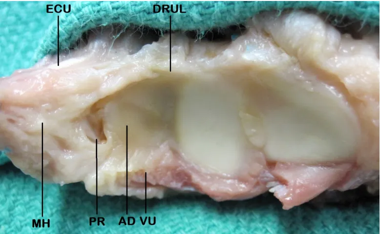
coined by Palmer and Werner1. The anatomic components include the dorsal and volar radioulnar ligaments with their superficial and deep fibers, the articular disc, meniscus homologue and extensor carpi ulnaris (ECU) subsheath (Figure 1.2). The articular disc is also referred to as the triangular fibrocartilage.
Figure 1.2: The Triangular Fibrocartilage Complex. AD = Articular Disc, PR = Prestyloid Recess, VU = Volar Ulnocarpal Ligaments (includes ulnolunate, ulnocapitate and ulnotriquetral ligaments) arising off the Volar Radioulnar Ligament (deep and not shown), DRUL = Dorsal Radioulnar Ligament, MH = Meniscus Homologue, ECU = Extensor Carpi Ulnaris (© B Gammon)
Figure 1.3: The volar surface of the forearm, flexor tendons retracted, depicting pronator quadratus (PQ) (© B Gammon)
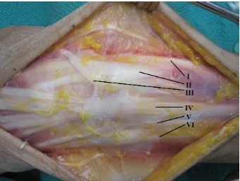
Figure 1.5: The anatomic components of the interosseous membrane (IOM), including the Distal IOM, Accessory Band and Central Band. The Distal Oblique Bundle is a sub-component of the Distal IOM and contributes to DRUJ stability when present (© B Gammon).
The DRUJ is comprised of the ulnar head and sigmoid notch. The ulnar head has an ovoid shape, which exerts a cam effect that is maximal in the neutral position. There is an area devoid of cartilage on the volar ulnar surface of the ulnar head termed the ulnar volar facet. Here the volar DRUJ capsule inserts, and this facet engages with the volar
rim of the sigmoid notch in pronation (Figure 1.6)2.
Other bony landmarks on the distal ulna include the articular dome, non-articular ulnar fovea, ulnar styloid and dorsal groove for ECU (Figure 1.7).
The distal ulnar dome sits beneath the articular disc of the TFCC complex while the fovea and styloid serve as attachment points for the superficial and deep fibers of the dorsal and volar radioulnar ligaments. The ECU tendon traverses the wrist and through part of its excursion runs in the dorsal ECU groove.
The concave sigmoid notch of the radius forms the opposing articular surface to complete this trochoid joint. The articular disc of the TFCC attaches at the distal aspect of the sigmoid notch.
Figure 1.7: Osseous and articular anatomy of the distal radius and ulna: SN= sigmoid notch, RI = radial insertion TFCC, LF = lunate facet, SF = scaphoid facet, EG = ECU groove, US = ulnar styloid, UF = ulnar fovea, UD = ulnar dome, USe = ulnar seat (© B Gammon)
The radius of curvature of the sigmoid notch is approximately 15 mm with 47-80o
of cartilaginous coverage. The ulnar head has a radius of approximately 10 mm. The
Figure 1.8: Radius of curvature and cartilaginous coverage of the ulnar head and sigmoid notch. The sigmoid notch has a larger radius of curvature relative to the ulnar seat. This lack of congruency causes a combined rolling and sliding interaction between the two surfaces during forearm rotation (© B Gammon).
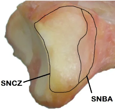
The thickness of cartilage on the articulating portion of the ulnar head is relatively homogenous across its surface, while on the sigmoid notch the cartilage is thicker
centrally2. On average only the distal aspect, comprising 69% of the sigmoid notch
surface area is covered in cartilage with a normal proximal bare area4. The cartilage thins
progressively moving from distal to proximal in the notch (Figure 1.9)2.
Seminal work by Tolat et al.5 defined the morphology of the sigmoid notch and its relationship to DRUJ stability. Four subtypes of morphology in the sagittal plane were described. They include, in order of descending prevalence: Flat Face, C-type, S-type and Ski Slope (Figure 1.10).
Flat Face C-Type S-Type Ski Slope
Figure 1.10: Sagittal plane morphology of the sigmoid notch: Flat Face, C-Type, S-Type and Ski Slope (© B Gammon).
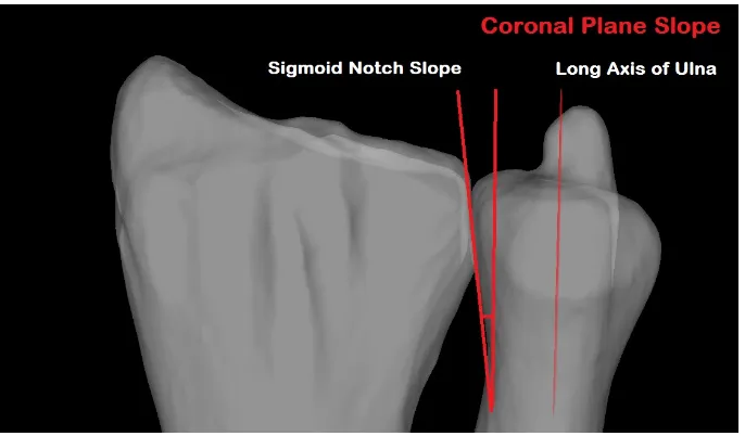
In the coronal plane, the DRUJ can also vary. The articular surface slope of the
sigmoid notch and ulnar head can be parallel, oblique or reverse oblique5. The mean
Figure 1.11: Coronal plane morphology of the DRUJ depicting a reverse oblique sigmoid notch, whose angle is measured off a line parallel to the long axis of the ulna (© B Gammon).
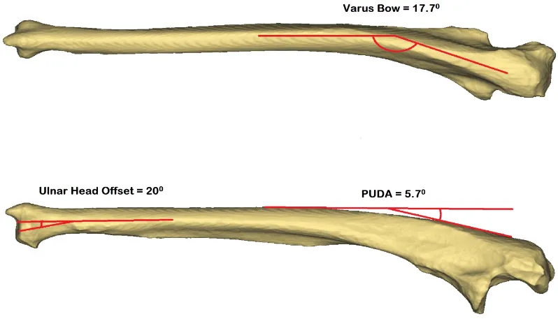
The distal ulnar diaphysis is relatively straight, with the ulnar head being laterally
offset from the long axis of the shaft by approximately 20° (range -14 to 41°)3,6.
Proximally, there is a varus bow which averages 17.7° (range 11-28°)7, as well as an
anterior bow termed the proximal ulna dorsal angulation or PUDA, which averages 5.7°
Figure 1.12: Bony anatomy of the ulna depicting the ulnar head offset, varus bow and proximal ulna dorsal angulation (PUDA) (© B Gammon).
The diaphysis of the radius is bowed in the sagittal and coronal planes, which prevents the forearm bones from impinging in pronation. In the coronal plane the bow is located in the middle third of the radius averaging 10.3° apex lateral. In the sagittal plane there is an apex dorsal bow between the tuberosity and midshaft of the radius averaging
Figure 1.13: Bony anatomy of the radius depicting the apex lateral bow in the coronal plane and apex dorsal bow in the saggital plane (© B Gammon).
1.2
Stabilizers of the DRUJ
Bony anatomy plays a significant role in the stability of the DRUJ. The dorsal and volar osseous rims prevent excessive dorsal and volar translation of the ulnar head within the sigmoid notch. The palmar rim is more prominent and deficiency in this region can
precipitate instability10. The DRUJ is inherently stable in supination, even when its
associated soft tissue stabilizers have been denuded11.
As was demonstrated in Figure 1.8 however, the DRUJ joint surfaces are relatively incongruous. Because of this articular incongruency, soft tissues also play a major role in the stabilization of this joint. DRUJ stability comes in part from the dorsal and volar
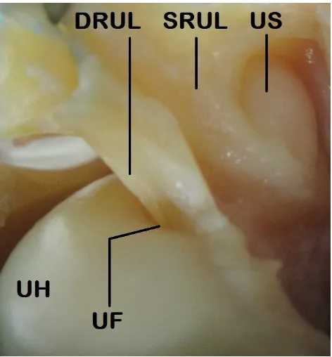
radioulnar ligaments12. These components of the TFCC (Figure 1.2) are considered some
Figure 1.14: A magnified view of the superficial fibers (SRUL) and deep fibers (DRUL) of the radioulnar ligaments, which attach onto the ulnar fovea (UF) and ulnar styloid (US). The ulnar head (UH) lies beneath © B Gammon.
The dorsal ligament tensions in pronation, buttressing the ulnar head in
conjunction with the dorsal rim of the sigmoid notch to prevent dorsal translation13,14,15,16.
In pronation, the volar radioulnar ligament also acts as a checkrein to keep the ulnar head
located3,17. Conversely, in supination the volar ligament tensions to hold the ulnar head
in the sigmoid notch, acting as a buttress in concert with the volar rim of the sigmoid
notch13,14,15,16. The dorsal radioulnar ligament acts as a checkrein to excessive volar
translation of the ulnar head in supination3,17. The foveal attachments have been found to
be the most important components conferring stability18. Even when all other stabilizers
are sectioned, the combination of the articular disc and distal radioulnar ligaments are
capable of maintaining normal DRUJ kinematics through forearm rotation12. Significant
dorsalpalmar instability occurs when the distal radioulnar ligaments are disrupted. However, provided they are at least partially intact, further stability can be obtained with
The ulnolunate and ulnotriquetral ligaments originate off the volar radioulnar ligament (Figure 1.2) and are in maximal tension with the forearm in supination. The
ulnocarpal collateral ligament is a structure originally described by Palmer and Werner1.
Its existence is controversial, and this tissue may consist of thickened ulnar capsule and
ECU subsheath20. When tested as a ligament, it seems to stabilize the ulnocarpal joint in
both pronation and supination14.
The articular disc (or triangular fibrocartilage) originates on the ulnar aspect of the lunate fossa and inserts into the dorsal and volar radioulnar ligaments peripherally (Figure 1.2). The disc glides over top of the ulnar dome, functioning to extend the lunate
facet’s articular surface and act as part of a mobile platform for the ulnar carpus2,21.
The meniscus homologue is a synovium-like soft tissue structure which occupies
the space between the articular disc, ulnocarpal capsule and triquetrum (Figure 1.2)22. It
helps to exert a sling effect, stabilizing the ulnar carpus. Between the meniscus
homologue and articular disc lies the prestyloid recess21. Variability has been found with
the morphology of this orifice, which was found to be narrow in 74% of specimens, wide
in 11% and absent in 15%22.
The DRUJ capsule plays an important role in stability. In fact, significant
restoration of DRUJ kinematics can be achieved by capsular repair alone23. In
histological studies the fiber orientation of the inferior capsule has suggested it has the ability to prevent axial translation. Dorsal and palmar translation is also constrained by the DRUJ capsule. The volar capsule is likely more important in this regard, with redundant oblique folds of tissue that act as a sling for the ulnar head in supination. The
dorsal capsule is thinner and accommodates the ulnar head in pronation24. Sectioning
studies have noted that the radius displaces volarly relative to the ulna in pronation when the dorsal capsule is sectioned. Similarly, the radius subluxes dorsally in supination
relative to the ulna when the volar capsule is sectioned25.
The PQ (Figure 1.3) functions as a dynamic stabilizer of the DRUJ when
contracted in full pronation26. Dynamic stability of the DRUJ is also conferred by
DRUJ. In the setting where the ulnar head is excised however, authors have noted that the PQ exacerbates DRUJ instability in pronation. In this scenario, contraction of the PQ during causes radioulnar convergence and subluxation of the radius dorsally relative to
the distal ulna27. Other authors have also noted this phenomenon, and found that ablation
of the ulnar head and styloid results in significant dorsopalmar instability in addition to
radioulnar convergence29,30,31.
The ECU (Figure 1.4) and its subsheath act as a dynamic stabilizer of the DRUJ32.
During pronation, ECU contraction causes the distal ulna to be depressed volarly relative to the ulnar carpus. The ECU actively stabilizes the DRUJ and ulnocarpal joints in neutral and supination, particularly in the setting of a sectioned TFCC. The ECU subsheath also acts as an adjunctive static stabilizer for the DRUJ, especially in the
neutral forearm position33
Finally, a note should be made of the IOM (Figure 1.5). It has been long established that the IOM prevents longitudinal motion between the radius and ulna. The central band is the strongest component; however in recent years more focus has been placed on the distal IOM for its contribution to secondary DRUJ stability. The distal IOM is taut in all forearm positions and has been found to prevent excessive dorsal/volar translation. It prevents volar ulnar displacement in pronation and dorsal ulnar displacement in
supination34. The distal IOM acts to stabilize the DRUJ once the distal radioulnar
ligaments have been injured15. Recent studies have evaluated this region of the IOM for
a thickened band of tissue, now termed the Distal Oblique Bundle35. Biomechanical
evidence suggests that specimens with a Distal Oblique Bundle have increased stability
of their DRUJ36.
1.3
DRUJ and Forearm Biomechanics
Figure 1.15: Centre of rotation of the forearm, passing through the centre of the radial head and ulnar fovea (© B Gammon).
During forearm motion, the radius rotates around the ulna distally through an arc of pronation (palm down) and supination (palm up). In most normal individuals the total arc of motion measures between 150-180°. Translational motion between the ulnar head and sigmoid notch also occurs in addition to rotation. This is due to their different radii of curvature, with the sigmoid notch having a 50-100% greater arc compared with the
ulnar head5. The ulnar head translates dorsally relative to the distal radius in pronation,
and volarly in supination11. Because of this obligate translation at the DRUJ, the
rotational axis of the forearm changes through pro-supination. In pronation, the axis of
rotation is at the radial side of the DRUJ and it moves ulnar in supination37. The radius
also translates proximally and distally relative to the ulna during forearm rotation37. In
pronation, ulnar length increases relative to the radius while in supination it
decreases38,39. With load, the relative changes in ulnar length increase during forearm
rotation37. The radiographic position of the radius and ulna in the coronal plane is termed
ulnar variance (Figure 1.16), and averages -0.9 mm (range -4.2 to 2.3 mm between individuals). The net radiographic result at the wrist is that the ulnar head moves distal
Load is distributed across both the radiocarpal and ulnocarpal joints, as well as through the DRUJ. Through an arc of simulated pronation and supination the joint
reaction force at the DRUJ has been found to vary between 2-10 N41. In supination, the
ulna comes into direct alignment with the carpus and accepts more axial load than in pronation. Generally, the distal ulna is felt to bear ~18% of the axial load, with the
balance supported by the distal radius38, though some authors have reported that it
supports up to 1/3 of the force placed across the wrist42. Varying muscle loads usually do
not affect the joint reaction force at the DRUJ in the setting of an intact TFCC41.
However, because of its load sharing properties, disruption of the distal radioulnar
ligaments increases the force that must be borne across the DRUJ articulation43.
The length of the radius relative to the ulna has also been found to play a role in force distribution across the ulnocarpal region and DRUJ. At the ulnocarpal joint, pressure
increases proportionally with radial shortening and decreases with radial lengthening44.
Shortening the ulna by 2.5 mm decreases ulnocarpal load to 4%, while increasing ulnar
length by 2.5 mm increases load to 42%38. At the distal radioulnar joint, radial
shortening (and resultant relative ulnar lengthening) had no effect on DRUJ pressure44.
However, progressive shortening of the ulna relative to the radius has been found to
increase pressures in the DRUJ44,45. Partial and complete sectioning of the TFCC
reduced peak pressure in the DRUJ, but the effect of increased pressure with further ulnar
shortening remained present45. This relates to the tension of the distal radioulnar
ligaments, DRUJ capsule, IOM and ulnocarpal ligaments, which are stretched with relative ulnar shortening and cause an increased DRUJ compressive force.
1.4
Distal Radius Malunion and its Influence on the
DRUJ
The normal geometry of the distal radius and its relationship to the distal ulna has
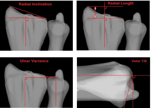
been previously reported46,47,48. It is described in terms of radial inclination, radial
length, ulnar variance and volar tilt based on plain radiographs. The distal radial articular surface has an average inclination of 24°, a radial length of 9-12 mm distal to the ulna, an
Figure 1.16: Measurement parameters for the distal radial articular surface, including radial inclination, length, ulnar variance and volar tilt (© B Gammon).
Distal radius fractures are an extremely common injury. Certain factors can predispose these to malunion, such as osteoporotic bone, significant initial fracture
displacement, patient age >60, and comminution49. Changes in the normal orientation of
the distal radius alters the kinematics of the distal radioulnar joint50,51,52,53,54. This relates
to the abnormal soft tissue tensions created as well as incongruency of the sigmoid notch relative to the ulnar head. Increasing the degree of malunion has a progressively
detrimental effect. Clinically, distal radius malunion has been associated with DRUJ dysfunction causing ulnar-sided wrist pain, restricted forearm rotation and in cases of a
1.5
Joint Contact at the DRUJ in Normal and
Malunited Conditions
An understanding of the biomechanics of an articulation, including its contact mechanics, is an important element in the assessment of joint function. However,
arthrokinematics, or the specific movement of joint surfaces57, have not been well defined
in the literature for the DRUJ.
Under normal conditions, articular contact is maximal in the neutral position,
comprising up to 60% of the DRUJ surface area58. There is minimal contact (less than
10% of the total DRUJ surface area) between the sigmoid notch and ulna at the extremes
of pronation and supination3. Ishii et al.22 evaluated pressure and contact area in the
DRUJ with loaded cadaveric forearm specimens using dynamic pressure sensitive film.
They reported that 12.5% of the sigmoid notch or 15.7 mm2 was in contact with the
DRUJ in the neutral position. They also described a centroid which was located at the dorsum of the sigmoid notch in pronation, and the volar aspect of the sigmoid notch in
supination. Shaaban et al.59 also looked at contact area within the DRUJ using dynamic
pressure sensitive film. They reported the least contact in extreme pronation, and a successive increase in contact up to 30° of supination, where contact was maximal,
reducing thereafter. In the loaded scenario this was 67.5 mm2, and there was no
significant effect from DRUL sectioning and repair. Similar to the findings of Ishii et al., these authors noted that the centroid of contact in the sigmoid notch moved dorsally with pronation and volarly with supination.
Crisco et al. examined the in vivo effects of distal radius malunion on articular contact in the DRUJ. Their subjects were live patients with chronically malunited distal radii, whose deformities included shortening, dorsal angulation and loss of radial inclination. The authors evaluated joint congruity using an interbone distance algorithm to give measurements of interbone spacing area (a proxy for contact area) and interbone spacing centroid location (analogous to a contact centroid). A threshold distance of 5 mm was
used. These authors reported a contact area of 215 mm2 in normal individuals, and 155
forearm rotation or along the volar-dorsal axis, though contact was on average 1.3 mm
more proximal in the malunited condition60.
1.6
Methods for Assessing Joint Contact
1.6.1
Direct Methods
Techniques to evaluate and quantify the contact area between opposing articular surfaces have evolved considerably over the past 30 years. Initial attempts were invasive and involved so-called “Direct” methods. One such technique is casting, which was
described by Stormont et al.61 as the most reproducible option. Casting entails the
injection of low viscosity cement into a joint, which is allowed to solidify and is subsequently extracted. The area devoid of cement is considered to represent the joint contact area (Figure 1.17).
Figure 1.17: A DRUJ casting illuminated on a lightbox. Note the central area devoid of casting material, which is designated as the contact patch (© B Gammon).
many authors to both quantify joint contact61,62,63,64,65 and also to validate new
techniques66,67. To our knowledge, it has not been used previously in the wrist.
Pressure sensitive film, such as Fujifilm Prescale (© Sensor Products Inc., Madison NJ), is another direct method of assessing joint contact area and pressure. The film is inserted into the joint, which is subsequently loaded in a single position. The distribution and magnitude of pressure created between two contacting surfaces can be ascertained from the colors displayed on the film. The film is calibrated such that a deeper pigment color reflects a higher contact pressure. Contact area can also be
quantified from the film. Disadvantages include the capsular and ligamentous sectioning that must occur to place the film in the joint, as well being labor-intensive. Only static recordings are possible, and the film is prone to artifact such as shear stress, staining and crinkling, particularly with curved joint surfaces. The interposition of this material (with a thickness of 0.11 mm) may also alter joint contact pressure and area. Pressure sensitive
film has previously been used in the wrist to quantify radiocarpal contact68,69.
A dynamic sensitive film sensor represents the evolution of
pressure-sensitive film. The most commonly reported version is Tekscan (© Tekscan Inc., South Boston MA) which is a thin pressure monitoring system comprised of numerous
individual sensing elements. Tekscan can be used to characterize and quantify both contact area and contact pressure, and has the advantage of providing real-time data through a range of joint motion. Disadvantages include its invasive introduction and artifact from wrinkling. Moreover, Tekscan has a thickness of 0.1 mm and like pressure sensitive film exerts a mass effect that may alter the bearing surface contact when inside
the joint. It has been used in both the radiocarpal joint70 and DRUJ22,44,45, 59,71.
1.6.2
Indirect Methods
Alternative methods of studying joint contact use indirect techniques. In this scenario, volumetric data from CT or MRI datasets can be used to generate 3-D bone and cartilage models. Contact measurements can be garnered from CT and MRI datasets directly, but the process is tedious. Authors have previously examined individual slices
felt to be inaccurate particularly for complex joints with undulating surfaces. Consequently, researchers have developed methods to measure joint contact using
proximity maps. These are created using the same 3-D models derived from CT73 or
MRI volumetric data sets66,74,75,76. Distance thresholds are set and contact area is
subsequently calculated using software algorithms. This method can also be used to establish the centroid of contact and has been validated against invasive techniques for use in the wrist77.
To further understand changes in joint function and contact, these indirect techniques can be applied in conjunction with simulated joint motion. Kinematic information can be collected directly from experimental cadaveric models (in vitro kinematics). Common techniques used to quantify joint kinematic data in vitro include
biplanar fluoroscopy78, electromagnetic tracking79, stereophotogrammetry80 and, most
recently, optical tracking54. 3-D models of the joint of interest are created using CT or
MRI volumetric datasets. These models are then registered, or matched, to the
experimental specimen’s anatomy using mathematical algorithms81,82,83,84. Proximity
maps are made from the registered 3-D models and optical tracking kinematic data67,85.
Thresholds for the overlap of models are used to characterize the location and area of
joint contact86,87. This allows for joint contact area to be measured through an arc of
motion using non-invasive, or indirect, methods. The dynamic evaluation of joint
surfaces and the characterization of their interaction is termed Arthrokinematics88.
Unlike in vitro methods where kinematics are measured directly, in vivo methods
compare relative joint positions on CT or MRI using computational means. The changes in the position and orientation of the models are then quantified. In vivo techniques have also been used to characterize kinematic changes in the carpal bones under various
experimental conditions89,90,91,92,93,94.
Presented in this thesis is a novel technique which utilizes a form of proximity
mapping termed Inter-cartilage Distance or ICD86. With ICD technique, bone and
relative to the optical trackers. The articulation is then CT scanned with air contrast, and 3-D models which include articular cartilage are subsequently generated from the
volumetric scan data. Fiducial based registration95 is then used to link the 3-D bone and
cartilage models, and restore their relative position and orientation from the testing procedure. The Inter-cartilage distance algorithm is used to create proximity maps of the DRUJ, and areas with cartilage overlap between models are designated as areas of contact86.
This method is an important advance because unlike the previously described
Inter-bone Distance (IBD) technique96, it accounts for regional variations in cartilage thickness
and location (Figure 1.19).
Figure 1.19: A flowchart demonstrating the methods by which contact centoid position for the DRUJ can be described relative to a centre point, with a coordinate system for the sigmoid notch generated using MatLAB (MATLAB 8.0, The MathWorks, Inc., Natick, Massachusetts, United States) (© B Gammon).
1.7
Rationale
Disorders of the distal radioulnar joint are a common clinical entity, and can be
associated with significant disability97. Post-traumatic instability of the DRUJ is one
such disorder, and is associated with TFCC insufficiency98,99. Patients often complain of
ulnar-sided wrist pain, a weak grip and occasionally mechanical symptoms such as a
sensation of subluxation97. Incongruency of the DRUJ following distal radius malunion
is another common clinical presentation100,101. Patients again present with ulnar-sided
wrist pain, decreased grip strength, restricted forearm rotation and visible deformity97,102.
It is theorized that these disorders can progress to osteoarthritis of the DRUJ in the
chronic setting, and that surgery may have a role in halting this process97.
Inter-cartilage Distance algorithm
used to create contact patch and
contact centroid
Coordinate sytem created and centre point calculated for
sigmoid notch in MatLAB
A variety of interventions have been described to alleviate symptoms from DRUJ
instability and malalignment. Open and arthroscopic TFCC repair103,104, DRUJ capsular
plication105, ulnar shortening osteotomy19 and DRUJ ligament reconstruction106,107 have
all been described to address TFCC insufficiency with concomitant DRUJ instability. Distal radius osteotomy can be effective for the treatment of symptoms from DRUJ
incongruency due to distal radial malunion56. The kinematic effect of these procedures
has been previously reported23,44,51,52,53,54,108,109,110.
Arthrokinematics examines the specific movement of joint surfaces, and new techniques have recently been developed, which accurately describe contact patterns in
diarthrodial joints57. Using these arthrokinematic techniques to evaluate joint contact will
improve our understanding of both normal joint function and effect of disorders such as ligamentous insufficiency or osseous deformity. Arthrokinematics can also be used to evaluate the effectiveness of rehabilitation protocols and surgical interventions in restoring normal joint contact patterns. The arthrokinematics of both the normal and pathologic DRUJ are poorly understood; therefore the purpose of this thesis will be to utilize the novel technique of Inter-cartilage Distance to describe and quantify these contact patterns.
1.8
Objectives and Hypotheses
Objectives:
1) To utilize the Inter-cartilage Distance algorithm to quantify joint contact at the
DRUJ and compare this method to gold standard techniques such as casting and Tekscan®.
2) To employ the Inter-cartilage Distance algorithm to characterize the in vitro
arthrokinematics of the DRUJ throughout an arc of simulated forearm supination.
3) To use Inter-cartilage Distance to describe and quantify the effect of simulated
Hypotheses:
1) Inter-cartilage Distance is effective at characterizing DRUJ contact patterns when
compared with other standardized techniques.
2) We theorize that: a) DRUJ contact area and centroid location will change with
forearm rotation and b) simulated active supination will increase contact area compared with passive supination.
3) We predict that: a) increasing dorsal angulation deformity of the distal radius will
decrease the DRUJ contact area and displace the contact centroid volarly and distally at the sigmoid notch b) sectioning of the TFCC will reduce DRUJ contact area and make the pathway of the contact centroid more variable.
1.9
Thesis Overview
In Chapter 2, contact area in the DRUJ is evaluated using Tekscan, casting and
Inter-cartilage Distance. A custom in vitro forearm positioning apparatus allows for the
1.10
References
1. Palmer AK, Werner FW. The triangular fibrocartilage complex of the wrist - anatomy and function. J Hand Surg Am. 1981;6(2):153-162.
2. Buck FM, Nico MA, Gheno R, Haghighi P, Trudell DJ, Resnick D. Morphology of the distal radioulnar joint: cadaveric study with MRI and MR arthrography with the forearm in neutral position, pronation, and supination. AJR Am J Roentgenol. 2010;194(2):202-207.
3. Ekenstam FA. Anatomy of the distal radioulnar joint. Clin Orthop Relat Res. 1992;(275):14-8.
4. Collins ED, Vossoughi F. A three-dimensional analysis of the sigmoid notch. Orthop Rev. 2011;3(2):e17.
5. Tolat AR, Stanley JK, Trail IA. A cadaveric study of the anatomy and stability of the distal radioulnar joint in the coronal and transverse planes. J Hand Surg Br.
1996;21(5):587-594.
6. Sagerman SD, Zogby RG, Palmer AK, Werner FW, Fortino MD. Relative articular inclination of the distal radioulnar joint: a radiographic study. J Hand Surg Am. 1995;20(4):597-601.
7. Windisch G, Clement H, Grechenig W, Tesch NP, Pichler W. The anatomy of the proximal ulna. J Shoulder Elbow Surg. 2007;16(5):661-6.
8. Rouleau DM, Faber KJ, Athwal GS. The proximal ulna dorsal angulation: a radiographic study. J Shoulder Elbow Surg. 2010;19(1):26-30.
10. Wallwork NA, Bain GI. Sigmoid notch osteoplasty for chronic volar instability of the distal radioulnar joint: a case report. J Hand Surg Am. 2001;26(3):454-9.
11. King GJ, Ogston NG, McMurtry RY, Rubenstein JD. Computerized tomography of the distal radioulnar joint: correlation with ligamentous pathology in a cadaveric model. J Hand Surg Am. 1986;11(5):711-717.
12. Gofton WT, Gordon KD, Dunning CE, Johnson JA, King GJ. Soft-tissue stabilizers of the distal radioulnar joint: an in vitro kinematic study. J Hand Surg Am.
2004;29(3):423-431.
13. Acosta R, Hnat W, Scheker L. Distal radio-ulnar ligament motion during supination and pronation. J Hand Surg Br. 1993;18(4):502-505.
14. DiTano O, Trumble TE, Tencer AF. Biomechanical function of the distal radioulnar and ulnocarpal wrist ligaments. J Hand Surg Am. 2003;28(4):622-627.
15. Kihara H, Short WH, Werner FW, Fortino MD, Palmer AK. The stabilizing mechanism of the distal radioulnar joint during pronation and supination. J Hand Surg Am. 1995;20(6):930-6.
16. Schuind F, An KN, Berglund L, Rey R, Cooney WP 3rd, Linscheid RL, Chao EY.
The distal radioulnar ligaments: a biomechanical study. J Hand Surg Am. 1991;16(6):1106-14.
17. Stuart PR, Berger RA, Linscheid RL, An K. The dorsopalmar stability of the distal radioulnar joint. J Hand Surg Am. 2000;25(4):689-699.
18. Haugstvedt J, Berger RA, Nakamura T, Neale P, Berglund L, An K. Relative contributions of the ulnar attachments of the triangular fibrocartilage complex to the dynamic stability of the distal radioulnar joint. J Hand Surg Am. 2006;31(3):445-451.
19. Nishiwaki M, Nakamura T, Nakao Y, Nagura T, Toyama Y. Ulnar shortening effect on distal radioulnar joint stability: a biomechanical study. J Hand Surg Am.
20. Nakamura T, Takayama S, Horiuchi Y, Yabe Y. Origins and insertions of the triangular fibrocartilage complex: a histological study. J Hand Surg Br. 2001;26(5):446-54.
21. Nakamura T, Yabe Y, Horiuchi Y. Dynamic changes in the shape of the triangular fibrocartilage complex during rotation demonstrated with high resolution magnetic resonance imaging. J Hand Surg Br. 1999;24(3):338-41.
22. Ishii S, Palmer AK, Werner FW, Short WH, Fortino MD. An anatomic study of the ligamentous structure of the triangular fibrocartilage complex. J Hand Surg Br.
1998;23(6):977-85.
23. Gofton WT, Gordon KD, Dunning CE, Johnson JA, King GJ. Comparison of distal radioulnar joint reconstructions using an active joint motion simulator. J Hand Surg Br. 2005;30(4):733-742.
24. Kleinman W, Graham T. The distal radioulnar joint capsule: clinical anatomy and role in posttraumatic limitation of forearm rotation. J Hand Surg Am. 1998 23(4):588-99
25. Watanabe H, Berger RA, An K, Berglund LJ, Zobitz ME. Stability of the distal
radioulnar joint contributed by the joint capsule. J Hand Surg Am. 2004;29(6):1114-1120.
26. Linscheid RL. Biomechanics of the distal radioulnar joint. Clin Orthop Relat Res. 1992;(275):46-55.
27. Gordon KD, Dunning CE, Johnson JA, King GJ. Influence of the pronator quadratus and supinator muscle load on DRUJ stability. J Hand Surg Am. 2003;28(6):943-950.
28. Stuart PR. Pronator quadratus revisited. J Hand Surg Br. 1996;21(6):714-22.
30. Sauerbier M, Fujita M, Hahn ME, Neale PG, Berger RA. The dynamic radioulnar convergence of the darrach procedure and the ulnar head hemiresection interposition arthroplasty: a biomechanical study. J Hand Surg Br. 2002;27(4):307-316.
31. Sauerbier M, Hahn ME, Berglund LJ, An K, Berger RA. Biomechanical evaluation of the dynamic radioulnar convergence after ulnar head resection, two soft tissue
stabilization methods of the distal ulna and ulnar head prosthesis implantation. Arch Orthop Trauma Surg. 2011;131(1):15-26.
32. Spinner M, Kaplan EB. Extensor carpi ulnaris. Its relationship to the stability of the distal radio-ulnar joint. Clin Orthop Relat Res. 1970;68:124-9.
33. Iida A, Omokawa S, Akahane M, Kawamura K, Takayama K, Tanaka Y. Distal radioulnar joint stress radiography for detecting radioulnar ligament injury. J Hand Surg Am. 2012;37(5):968-974.
34. Watanabe H, Berger RA, Berglund LJ, Zobitz ME, An K. Contribution of the Interosseous Membrane to Distal Radioulnar Joint Constraint. J Hand Surg Am. 2005;30(6):1164-1171.
35. Noda K, Goto A, Murase T, Sugamoto K, Yoshikawa H, Moritomo H. Interosseous membrane of the forearm: an anatomical study of ligament attachment locations. J Hand Surg Am. 2009;34(3):415-422.
36. Kitamura T, Moritomo H, Arimitsu S, Berglund LJ, Zhao KD, An KN, Rizzo M. The biomechanical effect of the distal interosseous membrane on distal radioulnar joint stability: a preliminary anatomic study. J Hand Surg Am. 2011;36(10):1626-1630.
37. Tay SC, van Riet R, Kazunari T, Koff MF, Amrami KK, An KN, Berger RA. A method for in-vivo kinematic analysis of the forearm. J Biomech. 2008;41(1):56-62.
39. Tay SC, van Riet R, Kazunari T, Amrami KK, An KN, Berger RA. In-vivo kinematic analysis of forearm rotation using helical axis analysis. Clin Biomech. 2010;25(7):655-659.
40. Tomaino MM. The importance of the pronated grip x-ray view in evaluating ulnar variance. J Hand Surg Am. 2000;25(2):352-7.
41. Gordon KD, Kedgley AE, Ferreira LM, King GJ, Johnson JA. Design and implementation of an instrumented ulnar head prosthesis to measure loads in vitro. J Biomech. 2006;39(7):1335-1341.
42. Shaaban H, Giakas G, Bolton M, Williams R, Wicks P, Scheker LR, Lees VC. The
load-bearing characteristics of the forearm: pattern of axial and bending force transmitted through ulna and radius. J Hand Surg Br. 2006;31(3):274-279.
43. Shaaban H, Giakas G, Bolton M, Williams R, Scheker LR, Lees VC. The distal radioulnar joint as a load-bearing mechanism - a biomechanical study. J Hand Surg Am. 2004;29(1):85-95.
44. Miura T, Firoozbakhsh K, Cheema T, Moneim MS, Edmunds M, Meltzer S. Dynamic effects of joint-leveling procedure on pressure at the distal radioulnar joint. J Hand Surg Am. 2005;30(4):711-718.
45. Nishiwaki M, Nakamura T, Nagura T, Toyama Y, Ikegami H. Ulnar-shortening effect on distal radioulnar joint pressure: a biomechanical study. J Hand Surg Am.
2008;33(2):198-205.
46. Jung JM, Baek GH, Kim JH, Lee YH, Chung MS. Changes in ulnar variance in relation to forearm rotation and grip. J Hand Surg Br. 2001;83(7):1029-33.
47. Medoff RJ. Essential radiographic evaluation for distal radius fractures. Hand Clin. 2005;21(3):279-288.
49. Bhattacharyya R, Morgan BS, Mukherjee P, Royston S. Distal radial fractures: the significance of the number of instability markers in management and outcome. Iowa Orthop J. 2014;34:118-22.
50. Adams BD. Effects of radial deformity on distal radioulnar joint mechanics. J Hand Surg Am. 1993;18(3):492-8.
51. Kihara H, Palmer AK, Werner FW, Short WH, Fortino MD. The effect of dorsally angulated distal radius fractures on distal radioulnar joint congruency and forearm rotation. J Hand Surg Am. 1996;21(1):40-7.
52. Fraser GS, Ferreira LM, Johnson JA, King GJ. The effect of multiplanar distal radius fractures on forearm rotation: in vitro biomechanical study. J Hand Surg Am.
2009;34(5):838-848.
53. Hirahara H, Neale PG, Lin Y, Cooney WP, An K. Kinematic and torque-related effects of dorsally angulated distal radius fractures and the distal radial ulnar joint. J Hand Surg Am. 2003;28(4):614-621.
54. Nishiwaki M, Welsh M, Gammon B, Ferreira LM, Johnson JA, King GJ. Distal radioulnar joint kinematics in simulated dorsally angulated distal radius fractures. J Hand Surg Am. 2014;39(4):656-663.
55. Brogren E, Wagner P, Petranek M, Atroshi I. Distal radius malunion increases risk of persistent disability 2 years after fracture: a prospective cohort study. Clin Orthop Relat Res. 2013;471(5):1691-1697.
56. Prommersberger K, Pillukat T, Mühldorfer M, van Schoonhoven J. Malunion of the distal radius. Arch Orthop Trauma Surg. 2012;132(5):693-702.
58. Ekenstam FA, Hagert CG. Anatomical studies on the geometry and stability of the distal radio ulnar joint. Scand J Plast Reconstr Surg. 1985;19(1):17-25.
59. Shaaban H, Giakas G, Bolton M, et al. Contact area inside the distal radioulnar joint: effect of axial loading and position of the forearm. Clin Biomech. 2007;22(3):313-318.
60. Crisco JJ, Moore DC, Marai GE, Laidlaw DH, Akelman E, Weiss AP, Wolfe SW. Effects of distal radius malunion on distal radioulnar joint mechanics - an in vivo study. J Orthop Res. 2007;25(4):547-555.
61. Stormont TJ, An KN, Morrey BF, Chao EY. Elbow joint contact study: comparison of techniques. J Biomech. 1985;18(5):329-36.
62. Eckstein F, Löhe F, Müller-Gerbl M, Steinlechner M, Putz R. Stress distribution in the trochlear notch. A model of bicentric load transmission through joints. J Bone Joint Surg Br. 1994;76(4):647-53.
63. Eckstein F, Löhe F, Hillebrand S, Bergmann M, Schulte E, Milz S, Putz R.
Morphomechanics of the humero-ulnar joint: I. Joint space width and contact areas as a
function of load and flexion angle. Anat Rec. 1995;243(3):318-26.
64. Liew VS, Cooper IC, Ferreira LM, Johnson JA, King GW. The effect of metallic radial head arthroplasty on radiocapitellar joint contact area. Clin Biomech.
2003;18(2):115-8.
65. Moungondo F, El Kazzi W, van Riet R, Feipel V, Rooze M, Schuind F.
Radiocapitellar joint contacts after bipolar radial head arthroplasty. J Shoulder Elbow Surg. 2010;19(2):230-235.
67. Lalone EA, Peters TM, King GW, Johnson JA. Accuracy assessment of an imaging technique to examine ulnohumeral joint congruency during elbow flexion. Comput Aided Surg. 2012;17(3):142-152.
68. Viegas SF, Tencer AF, Cantrell J, Chang M, Clegg P, Hicks C, O'Meara C,
Williamson JB. Load transfer characteristics of the wrist. Part I. The normal joint. J Hand Surg Am. 1987;12(6):971-978.
69. Pogue DJ, Viegas SF, Patterson RM, Peterson PD, Jenkins DK, Sweo TD, Hokanson JA. Effects of distal radius fracture malunion on wrist joint mechanics. J Hand Surg Am. 1990;15(5):721-7.
70. Short WH, Werner FW, Green JK, Masaoka S. Biomechanical evaluation of ligamentous stabilizers of the scaphoid and lunate. J Hand Surg Am. 2002;27(6):991-1002.
71. Deshmukh SC, Shanahan D, Coulthard D. Distal radioulnar joint incongruity after shortening of the ulna. J Hand Surg Br. 2000;25(5):434-8.
72. Van Ginckel AV, Van Ginckel A, Roosen P, Almqvist KF, Verstraete K, Witvrouw E. Effects of in vivo exercise on ankle cartilage deformation and recovery in healthy volunteers: an experimental study. Osteoarthritis Cartilage. 2011;19(9):1123-1131.
73. Marai GE, Laidlaw DH, Demiralp C, Andrews S, Grimm CM, Crisco JJ. Estimating Joint Contact Areas and Ligament Lengths From Bone Kinematics and Surfaces. IEEE Trans Biomed Eng. 2004;51(5):790-799.
74. Cohen ZA, McCarthy DM, Kwak SD, Legrand P, Fogarasi F, Ciaccio EJ, Ateshian GA. Knee cartilage topography, thickness, and contact areas from MRI: in-vitro calibration and in-vivo measurements. Osteoarthritis Cartilage. 1999 Jan;7(1):95-109.
76. Boyer PJ, Massimini DF, Gill TJ, Papannagari R, Stewart SL, Warner JP, Li G. In vivo articular cartilage contact at the glenohumeral joint: preliminary report. J Orthop Sci. 2008;13(4):359-365.
77. Fischer KJ, Johnson JE, Waller AJ, McIff TE, Toby EB, Bilgen M. MRI-based modeling for radiocarpal joint mechanics: validation criteria and results for four specimen-specific models. J Biomech Eng. 2011;133(10):101004.
78.Smith DK, Cooney WP 3rd, An KN, Linscheid RL, Chao EY. The effects of
simulated unstable scaphoid fractures on carpal motion. J Hand Surg Am. 1989;14(2 Pt. 1):283-91.
79. Dunning CE, Duck TR, King GJ, Johnson JA. Simulated active control produces repeatable motion pathways of the elbow in an in vitro testing system. J Biomech. 2001;34(8):1039-48.
80. Soslowsky LJ, Flatow EL, Bigliani LU, Pawluk RJ, Ateshian GA, Mow VC. Quantitation of in situ contact areas at the glenohumeral joint: a biomechanical study. J Orthop Res. 1992;10(4):524-34.
81. Maurer CR Jr, Maciunas RJ, Fitzpatrick JM. Registration of head CT images to physical space using a weighted combination of points and surfaces. IEEE Trans Med Imaging. 1998;17(5):753-61.
82. Ma B, Ellis RE. Robust registration for computer-integrated orthopedic surgery: Laboratory validation and clinical experience. Med Image Anal. 2003;7(3):237-250.
83. Besl P, McKay ND. A method for registration of 3-D shapes. IEEE Trans. on Pattern Analysis and Machine Intelligence. 1992; 14(2): 239–256.
85. Lalone EA, McDonald CP, Ferreira LM, Peters TM, King GW, Johnson JA. Development of an image-based technique to examine joint congruency at the elbow. Comput Methods Biomech Biomed Engin. 2013;16(3):280-290.
86. Willing R, Lapner M, Lalone EA, King GW, Johnson JA. Development of a
computational technique to measure cartilage contact area. J Biomech. 2014;47(5):1193-7.
87. Lalone EA, Giles JW, Alolabi B, Peters TM, Johnson JA, King GW. Utility of an image-based technique to detect changes in joint congruency following simulated joint injury and repair: an in vitro study of the elbow. J Biomech. 2013;46(4):677-82.
88. Baeyens J, van Glabbeek F, Goossens M, Gielen J, van Roy P, Clarys J. In vivo 3D arthrokinematics of the proximal and distal radioulnar joints during active pronation and supination. Clin Biomech. 2006;21 Suppl 1:S9-12.
89. Wolfe S, Crisco J, Katz L. A non-invasive method for studying in vivo carpal kinematics. J Hand Surg Br. 1997;22(2):147-152.
90. Moritomo H, Murase T, Goto A, Oka K, Sugamoto K, Yoshikawa H. Capitate-based kinematics of the midcarpal joint during wrist radioulnar deviation: an in vivo three-dimensional motion analysis. J Hand Surg Am. 2004;29(4):668-675.
91. Goto A, Moritomo H, Murase T, Oka K, Sugamoto K, Arimura T, Masumoto J, Tamura S, Yoshikawa H, Ochi T. In vivo three dimensional wrist motion analysis using magnetic resonance imaging and volume based registration. J Orthop Res.
2005;23(4):750-6.
92. Johnson JE, Lee P, McIff TE, Toby EB, Fischer KJ. Scapholunate ligament injury adversely alters in vivo wrist joint mechanics: An MRI-based modeling study. J Orthop Res. 2013;31(9):1455-1460.
94. Rainbow MJ, Kamal RN, Leventhal E, Akelman E, Moore DC, Wolfe SW, Crisco JJ. In vivo 3-dimensional analysis of dorsal intercalated segment instability deformity secondary to scapholunate dissociation: a preliminary report. J Hand Surg Am. 2013;38(7):1346-1355.
95. Kaufmann R, Pfaeffle J, Blankenhorn B, Stabile K, Robertson D, Goitz R.
Kinematics of the midcarpal and radiocarpal joints in radioulnar deviation: an in vitro study. J Hand Surg Am. 2005;30(5):937-942.
96. Lalone EA, McDonald CP, Ferreira LM, Peters TM, King GW, Johnson JA. Development of an image-based technique to examine joint congruency at the elbow. Comput Methods Biomech Biomed Engin. 2013;16(3):280-290.
97. Murray PM, Adams JE, Lam J, Osterman AL, Wolfe S. Disorders of the distal radioulnar joint. Instr Course Lect. 2010;59:295-311.
98. Ehman EC, Hayes ML, Berger RA, Felmlee JP, Amrami KK. Subluxation of the
distal radioulnar joint as a predictor of foveal triangular fibrocartilage complex tears. J Hand Surg Am. 2011;36(11):1780-1784.
99. Moriya T, Aoki M, Iba K, OzasaY, Wada T, Yamashita T. Effect of triangular ligament tears on distal radioulnar joint instability and evaluation of three clinical tests: a biomechanical study. J Hand Surg Br. 2009;34(2):219-223.
100. Fujitani R, Omokawa S, Akahane M, Iida A, Ono H, Tanaka Y. Predictors of distal radioulnar joint instability in distal radius fractures. J Hand Surg Am. 2011;36(12):1919-1925.
101. Kim JP, Park MJ. Assessment of distal radioulnar joint instability after distal radius fracture: comparison of computed tomography and clinical examination results. J Hand Surg Am. 2008;33(9):1486-1492.
103. Shinohara T, Tatebe M, Okui N, Yamamoto M, Kurimoto S, Hirata H.
Arthroscopically assisted repair of triangular fibrocartilage complex foveal tears. J Hand Surg Am. 2013;38(2):271-277.
104. Atzei A, Rizzo A, Luchetti R, Fairplay T. Arthroscopic foveal repair of triangular fibrocartilage complex peripheral lesion with distal radioulnar joint instability. Tech Hand Up Extrem Surg. 2008;12(4):226-35.
105. Manz S, Wolf MB, Leclère FM, Hahn P, Bruckner T, Unglaub F. Capsular
imbrication for posttraumatic instability of the distal radioulnar joint. J Hand Surg Am. 2011;36(7):1170-1175.
106. Lawler E, Adams BD. Reconstruction for DRUJ Instability. Hand (N Y). 2007;2(3):123-126.
107. Adams B, Berger R. An anatomic reconstruction of the distal radioulnar ligaments for posttraumatic distal radioulnar joint instability. J Hand Surg Am. 2002;27(2):243-51.
108. Petersen MS, Adams BD. Biomechanical evaluation of distal radioulnar reconstructions. J Hand Surg Am. 1993;18(2):328-34.
109. Saito T, Nakamura T, Nagura T, Nishiwaki M, Sato K, Toyama Y. The effects of dorsally angulated distal radius fractures on distal radioulnar joint stability: a
biomechanical study. J Hand Surg Br. 2013;38(7):739-745.
110. Ferreira LM, Greeley GS, Johnson JA, King GW. Load transfer at the distal ulna following simulated distal radius fracture malalignment. J Hand Surg Am.
2
Comparison of Inter-cartilage Distance as a Method for
Assessing Arthrokinematics of the Distal Radioulnar
Joint
2.1
Overview
This chapter presents an in-vitro cadaveric study examining the accuracy of Inter-cartilage Distance as a tool for measuring contact area in the distal radio-ulnar joint. It is compared to other direct methods of contact area measurement including Casting and Tekscan®.
2.2
Introduction
As documented in Chapter 1, the distal radioulnar joint (DRUJ) is a complex,
diarthrodial articulation which, in conjunction with the proximal radioulnar joint (PRUJ), allows for the radius to rotate around the ulna during forearm pronation and supination. There is a combined rolling and sliding motion that occurs as the radius glides over the
ulnar head1. The area of ulnar head contacting the sigmoid notch changes depending on
the position of forearm rotation2.
The joint contact pattern between the radius and ulna at the DRUJ is of interest, as it gives insight into how the radius and ulna interact during normal and pathological
conditions. Ulnar-sided wrist pain is a common complaint in patients with a malunion of
the distal radius3. Incongruence at the DRUJ may contribute to these symptoms. Thus, it
is important to be able to quantify changes in the arthrokinematics of this articulation so this phenomenon can be further studied.
As described previously in Chapter 1 (Section 1.6), there are both direct and indirect methods described to assess joint contact. Direct methods include casting, pressure
sensitive film and piezoresistive array pressure sensors(Tekscan®). The “direct” gold
standard for accuracy is considered to be casting4. This reference standard technique is
limited in its applicability as the joint capsule must be sectioned to remove the cast, and
only static positions can be examined. Piezoresistive array pressure sensorsrepresent an