Volume 8, No. 4, May 2017 (Special Issue)
International Journal of Advanced Research in Computer Science REVIEW ARTICLE
Available Online at www.ijarcs.info
© 2015-19, IJARCS All Rights Reserved 295
Design and Performance of Solar Tracking Photo-Voltaic System using Microcontroller
Zahoor Ahmad Suraya Sharief
Assistant Professor Assistant Professor
Department of Electrical Engineering Department of Electrical Engineering Islamic unicersity of Science & Technology Islamic unicersity of Science & Technology
Awantipora, J&K India Awantipora, J&K India [email protected] [email protected]
Abstract —Solar power generation had been employed as a renewable energy for years ago. Residents that use solar power as their alternative power supply will bring benefits to them The main objective of this paper is to develop a microcontroller-based solar panel tracking system which will keep the solar panels aligned with the Sun in order to maximize in harvesting solar power without unnecessary consumption of motor energy.[1] In an ordinary solar power system the sunlight was not used to the maximum extent and so in order to take the system to the highest potential, solar tracking system was employed. This paper shows design and realization of automatic solar panel orientation system in order to achieve high performances. This can be done by keeping the solar panel at 90 degree to the sun rays. To achieve this, components like PIC microcontroller, a DC gear motor, solar panel, and a gear wheel arrangement were used. The solar tracking system operates by the comparison of voltages using solar cell array, which is connected to the PIC microcontroller. And so, the main panel rotates where the maximum light is absorbed. As a result of using this solar tracking system, the efficiency of the system was found to be increasing when compared to the system that does not use the process of solar tracking.[2]
Keywords — Solar Tracking, Solar Panel, Microcontroller, DC Gear Motor, Sensors.
I. INTRODUCTION
The solar energy is known to be one of the preferred renewable green energies, which is much cleaner and free from harmful production to the environment compared with the conventional counterparts [1, 2]. Maximizing power output from a solar system is desirable to increase efficiency. In order to maximize power output from the solar panels, one need is to keep the panels aligned with the sun, means that the tracking of the sun is required [3]. Solar trackers are the most appropriate and proven technology to increase the efficiency of solar panels through keeping the panels aligned with the sun’s position. Solar trackers get popularized around the world in recent days to harness solar energy in most efficient way [4, 5].The main objective of this paper is to design the sun tracking solar system model which is a device that follow the movement of the Sun regardless of motor speed. In this project we can also implement an energy efficient method to control the Light Emitting Diode (LED) street lights.
Besides that, it is to improve the overall electricity generation using single axis sun tracking system and also to provide the design for residential use.
system and also to provide the design for residential use.LDR or light dependent resistor has been chosen as the sensor because LDR is commonly used in sun tracking system. This is because LDR is sensitive to the light. The resistance of LDR will decreases with increasing incident light intensity [12]. For the controller, PIC18F877A had been chosen. This PIC programming will give the pulse to the driver to move the motor. For the driver, bidirectional DC motor control using relay has been used. The motor controller had been chosen because it can control the motor to rotate clockwise and counter-clockwise easily. DC geared motor also been chosen because it has a hold torque up to 24 kg.cm and low rpm. Last but no least, LM7805 is
used to convert the input voltage from the source to 5 V output because integrated circuit only need 5 V to operate.
II. METHODOLOGY
This project is divided into two parts, hardware development and programming development. Figure 1
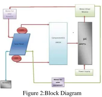
[image:2.595.311.561.292.550.2]shows block diagram of the project.
Figure 2:Block Diagram
The project is built using a balanced concept which is two signals from the different sensors are compared Light Dependent Resistor (LDR) as a light sensor has been used. The two light sensor are separated by divider which will create shadow on one side of the light sensor if the solar panel is not perpendicular to the sun. For the controlling circuit, microcontroller 16F877A acts as a brain that controls the movement of the motor via relay. Data received from the sensors and processed by the microcontroller (PIC16F877A). The microcontroller will send a data to the Bi-directional DC-geared motor via relay to ensure solar panel is perpendicular towards the Sun. Relay controls the rotation of the motor either to rotate clockwise or
anticlockwise. The solar panel that attached to the motor will be reacted according to the direction of the motor.
III COMPONENTS IN THE CIRCUIT
Solar panel
PIC16F877A microcontroller
Light dependent resistor (LDR)
DC gear motor
Battery,Comparator circuit
Motor driver,Regulated Power Supply
A. SOLAR PANEL SPECIFICATIONS:
Table 1. Specifications of Hardware
TYPE Monocrystalline Si
Solar cell
Weight 450 g
Size 190×190×5 mm
No of cells 36
Max Power 6 Watts
Max Power Voltage 18 V
Max Power Current 0.3 A
Open Circuit Voltage 20 V
Short Circuit Current 0.9 A
Figure 3: Photovoltaic panel or array
MATHEMATICAL ANALYSIS
Vmax=18V Vmin=0(approx) Current (I) =0.3A Imax =0.9A
Power=6W ; Force (F) =mass×acceleration F=450×9.8=4.41N
Torque (T) =F×radius(r) =4.41×0.045
[image:2.595.71.241.435.597.2]© 2015-19, IJARCS All Rights Reserved 297
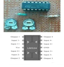
B.Sensor
[image:3.595.317.500.86.215.2][image:3.595.41.504.89.216.2]
Figure 4: sensor circuits
Table 1: LDR output voltage from solar sensor circuit
SUNLIGHT VRLDR VLLDR
EXPOSED 3.7V 0.75V
NOT EXPOSED 3.5V 1.6V
C. DC MOTOR AND MOTOR DRIVER THEORY:
The tracking system would need to consist of a motor which controls the position of the panel and a control circuit to direct these motors .DC Geared motor is actually an assembly of two things a normal DC motor and a Gear reduction unit.
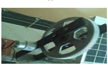
GEAR ARRANGEMENT
To make the externally connected mechanical hardware rotate at the required speed, gear arrangement was done. A small gear was attached to the motor & another large gear was attached to the hardware, so that the speed gets reduced. The speed produced by the motor gets reduced to the required number of times & then reaches the mechanical hardware through large gear & chain arrangement. The gear ratio will be 10:1.
MATHEMATICAL ANALYSIS:
Specification: 12 Volt, 6 Watt, 20 rpm
The unique of the designed system is the speed of DC geared motor is the speed of DC geared is neglected because the motor offers low output rated speed 20 rpm and high output rated torque. Therefore speed of motor is not critical consideration during design process. The main consideration of the designed system is direction of motor rotation and this matter has been tackled by considering the driver circuit.
Gear Ratio=Ratio of input speed relative to output speed OR Ratio of number of output teeth to the number of output teeth .Therefore, Gear ratio =128/12
=10(approx) i.e. 10:1
Figure 5: Gear Arrangement
Also output Power (P) = Torque (T) ×Angular velocity (Ω)
P = T×2πN/60
T = (P×60)/2Πn
T = (6×60)/2× 3.14×20
T = 18/6.28
T = 2.86 Nm =29 Kg-cm
H-BRIDGE MOTOR DRIVER:
The PIC controls the rotation of the base plat form in both directions, clockwise and counter clock wise. To reverse the rotation direction of the permanent magnet DC motor, the polarity of the applied voltage must be reversed. Though there are several H bridge drivers like L 293D, L 6202D but here we implement H bridge by using four transistors.
[image:3.595.352.525.308.412.2]been used in H – bridge to drive a motor in both directions (clockwise and anti clock wise).
Description of circuit can be divided in to two parts .First part explain the concept behind the working transistor as switch and second part the function and operation of H-
bridge.As a Switch; when there is no input on the base, the transistor is in cut-off region and act as open switch .When the base is given an input through a resistor R the transistor get biased and enters in to saturation state, hence behave like a closed switch. It is clear from Fig. 6 that the PIC controls to the H-bridge using ports RB0 and RB1( pin33 and pin 34)
INPUT(A&B) from microcontroller T1 T2 T3 T4 Direction of Motor
00 OFF OFF ON ON REST
01 OFF ON ON OFF CLOCKWISE
10 ON PFF OFF ON COUNTER CLOCK
[image:4.595.105.494.183.345.2]WISE
Figure 6
This IC driver amplifies the input voltage and protects the micro controller from back electromotive force. Generally motor generates back electromotive forces .This may damage the motor.
D. IC LM324N COMPARATOR: Here IC LM324N is
[image:4.595.353.523.378.714.2]used to compare the analog signals.
Figure 7: Comparator circuit
E. IC 7805 VOLTAGE REGULATOR CIRCUIT. IC
7805 is a 5V voltage regulator that restricts the voltage output to 5V and draws 5V regulated power .We have designed 5V dc supply for internal operation of microcontroller as shown in fig 9.
IV. HARDWARE OPERATION
Figure :8
Figure:9
Figure:10
[image:4.595.91.226.473.614.2]
© 2015-19, IJARCS All Rights Reserved 299 whole light energy so we have made a tracking system in
which solar panel can be rotated as per the sun changes its position .The 12v dc input voltage is injected to the PCB .This 12 volt dc supply is used to run different component in
the circuit. This 12volt dc supply also goes to 7805 voltage regulator from where the output 5volt dc spread to all logic circuitry. The 12volt dc supply is only for relay, LM324N,
and Motor Driver. There is also a reset switch for controlling necessary condition. Two LDR’S are arranged on the edges of solar panel. Panel is arranged in such a way
that light on two LDR’S is compared and panel is rotated towards LDR which have high intensity. When the intensity
of light falling on right LDR is more panel slowly moves towards the right and if intensity on the left LDR is more panel slowly moves towards the left. In the noon sun is ahead and intensity of light on both LDR is same, In such cases panel is constant and there is no rotation. The voltage
signal of each LDR’S sensor that are compared by LM324 are fed to the microcontroller .Microcontroller receive voltage signal from any input output pin of the controller
and performs operation according to its own algorithm.
When the controller finds the highest voltage level of any LDR sensor gives instruction to the motor through the motor
driver circuit to rotate the panel on the single axis in the direction of LDR sensor which are generating highest voltage output. So the battery can recharge appropriately
through the solar panel and we can run any electronic devices here we can use this energy for street light system. As by rotating the solar panel in the direction of the sun we
utilize the maximum energy of the sun.
This system also demonstrate the usage of LED as light source .LED’s are low power consuming devices as compared to fluorescent lamps .Another LDR is also applied here for controlling the intensity of street light and stops the unnecessary working of motor during night.LDR resistance drastically reduces according to the day light .Its output is connected to the microcontroller pin, microcontroller comprises programmable instruction that controls the light intensity .These street lights completely shut down at morning during day and continues again during night.
V .COMPARISON OF FIXED MOUNT WITH SINGLE AXIS TRACKER SYSTEM:
HOURS STATIC PANEL SOLAR TRACKING AXIS
Voltage (V)
Current (mA)
Power (mW)
Voltage (V)
Current (mA)
Power (mW)
1000 16.8 4.2 70.56 17.5 4.9805 87.158
1100 17.3 4.325 74.823 18.1 5.15126 93.238
1200 17.8 4.45 79.21 18.5 5.2651 97.404
1300 18.3 4.575 83.723 19.1 5.43586 103.825
1400 18.8 4.7 88.36 19.8 5.63508 111.575
1500 17.1 4.275 73.103 18.0 5.1228 92.404
1600 16.6 4.15 68.89 17.5 4.9805 87.158
Figure: 11
VI. SIMULATION RESULTS: Characteristic of LDR’s
Figure:12
RESULT 1:LDR TOP RESULT 2:LDR BOTTOM
Figure: 13
VII. ADVANTAGES
The main advantage of this system is low power consumption. It takes very less power which can be also derived directly from the solar panel or from a DC battery with recharging mechanism. In the evening when sun sets, the solar panel stops rotating and on the next day it has to come to its original position. In other systems, this task is done using another mechanism for retracing back the path during night. But in our system this is achieved by using a Light Dependent Resistor(Sensor) which stops the motor
next day. This saves the energy which is required to power up the extra circuitry for retrace mechanism. This means that our mechanism becomes active only when sun is present, hence it can always get the power from sun.
VIII. CONCLUSION
© 2015-19, IJARCS All Rights Reserved 301 by 24% and it was found that all the parts of the
experimental setup are giving good results.. Moreover, this tracking system does track the sun in a continuous manner. And this system is more efficient and cost effective in long run. From the results it is found that, by automatic tracking system, there is gain in increase of efficiency when compared with non-trackingsystem.
Hence reliable,economical, compact and efficient system of solar energy conversion had been made possible with this design. The system can be applied in the residential area for alternative electricity generation especially for non-critical and low power appliances.In a nutshell, the output of this effort is just a small drop in the big ocean of science and technology, in order to make life simpler, easier and enjoyable.
IX.FUTURE SCOPE
The goals of this project were purposely kept within what was believed to be attainable within the allotted timeline. As such, many improvements can be made upon this initial design. That being said, it is felt that this design represents a functioning miniature scale model which could be replicated to a much larger scale. The following recommendations are provided as ideas for future expansion of this project:
Remedy the motor binding problems due to the photo sensor leads. This could be done with some sort of slip ring mechanism, smaller gauge wire, a larger motor with more torque, or a combination of some or all of these ideas. Increase the sensitivity and accuracy of tracking by using a different light sensor. A photodiode with an amplification circuit would provide improved resolution and better tracking accuracy/precision. Different algorithm can be followed for more efficient tracking. This device can be given more intelligence, such as after tracking once, it will able to predict the line of movement of the sun across the sky.
REFERENCES
[1] Aryuanto Soetedjo. Modeling of Maximum Power Point Tracking Controller for Solar Power System.
[2] TELKOMNIKA Indonesian Journal of Electrical Engineering. 2012; 10(3): 419-430.
[3] Yuhong Zhao, Xuecheng Zhao, Yunhui Zhang. MPPT for Photovoltaic System Using Multi-objective
[4] Improved Particle Swarm Optimization Algorithm TELKOMNIKA Indonesian Journal of Electrical
Engineering, January 2014; 12(1): 261~ 268.
[5] Syed Arsalan. Sun Tracking System with Microcontroller 8051. International Journal of Scientific &
Engineering Research, June-2013; 4(6).
[6] A.K. Saxena and V. Dutta, “A versatile microprocessor based controller for solar tracking,” in Proc. IEEE, 1990, pp. 1105 – 1109.
[7] Tamara A. Papalias and Mike Wong, “Making Sense of Light Sensors”, Application notes, CA: Intersils Americas Inc. 2007. [8] David Appleyard, “Solar Trackers: Facing the Sun”, Renewable Energy World Magazine, UK: Ralph Boon, June 1, 2009.
[9] S. J. Hamilton, “Sun-tracking solar cell array system,” Department of Computer Science and Electrical Engineering, University of
Queensland, Bachelors Thesis, 1999.
[10] N. Amin, W. C. Yung and K. Sopian, “Low Cost Single Axis Automated Sunlight Tracker Design for Higher PV Power Yield” ISESCO Science and Technology Vision, Volume 4, November 2008.
[11] Han Wan Siew, “Solar Tracker” SIM University, 2008. [12] Jyotirmay Gadewadikar, “Microprocessor Based Solar Tracking System Using Stepper Motor” S.G.S. Institute of Tech. & Science,
Indore.
[13] David Appleyard, “Solar Trackers: Facing the Sun”, Renewable Energy World Magazine, UK: Ralph Boon, June 1, 2009.
[15] www.projectsof16f877A.com , www.slideshare.net
[16 ] www.youtube.com , www.engineeargarage.com ,www.circuit today.com