INVERTER DEAD-TIME ELIMINATION FOR REDUCING HARMONIC
DISTORTION AND IMPROVING POWER QUALITY
R.Narmatha
II.M.E-Power Electronics &Drives, Muthayammal Engineering College, Rasipuram Namakkal, India
T.Govindaraj
Head of Electrical and Electronics Engineering, Muthayammal Engineering College, Rasipuram, Namakkal, India
ABSTRACT
Numerous studies have been presented to eliminate dead-time effect. This paper will present a
dead-time elimination scheme for a sinusoidal pulse width modulation (SPWM) controlled inverter.
In comparison to using expensive current sensor, this method precisely determine the load current
polarity by detecting the terminal voltage of the antiparallel diode of power devices. The presented
scheme includes the freewheeling current polarity detection circuit and the PWM control generator
without dead-time. This method significantly reduces the output voltage loss, harmonic distortion
and improves quality of power. Simulation results are given to demonstrate the effectiveness of the
dead-time elimination scheme.
Keywords:
Dead time elimination, sinusoidal pulse width modulation (SPWM).INTRODUCTION
The state of the art in motor control provides an adjustable voltage and frequency to the terminals
of the motor through a pulse width modulated (PWM) voltage source inverter drive. As the power
devices change switching states, a dead time exists. Dead- time is used for sinusoidal pulse
width-modulation (SPWM)-controlled inverter control to avoid “short through” of high-side and low-side
power devices. The dead-time mainly depends upon characteristics of power devices and gate drive
circuit. The effects of dead time include output voltage loss and current distortion. These effects
become relevant as voltage is low and switching frequency is high. Moreover, addition of dead
time to a PWM-controlled inverter also affects the common-mode voltage.
Several methods have been presented to deal with the dead-time issue. These methods include
dead-time compensation, dead-time elimination and dead-time minimization. To overcome the
Journal of Asian Scientific Research
dead-time effects, the authors (Yong Wang, Qiang Gao, and Xu Cai, 2011)propose many dead-time
compensation solutions. They are all developed based upon the knowledge of the current direction.
In order to determine the direction of current, an accurate current sensor is required. However, the
result is highly affected by the harmonics around the zero-crossing points, particularly when the
current is small.For the dead-time minimization method, dead time is still required when the
current is around zero-crossing points in which current polarity detection is difficult and not
accurate.
Table-1.Comparison of Different Methods
In (David and Russel, 2008; Yong and Yen, 2009), current polarity is determined by detecting the
terminal voltages of the antiparallel diode of a power device. Therefore, the dead-time elimination
method is developed based upon the detection method. However, two power sources are required
for each inverter leg or half-bridge of converter. For a three-phase inverter, four power sources for
such detection circuits are required.Moreover, the conduction states of power antiparallel diode are
detected only at the instants of rising edge of chop on, as shown in. It may result in detection error
due to switching noise and current ripple in practice and therefore cause commutation error.
More details of the comparisons are summarized in Table I. There are three categories: dead-time
compensation; time elimination; and time minimization. This paper will present a
dead-time elimination scheme for PWM-controlled inverter. The presented dead-dead-time elimination
scheme does not require separate power supplies for freewheeling-current detection of high- and
low-side power devices. Therefore, only one power source is required for freewheeling-current
polarity detection of three-phase inverter/converter. Method Dead time
compensation Dead time elimination Dead time minimization Proposed method Current sensor
o × o ×
Isolated
power
× o × ×
Dead
time
The presented scheme includes the freewheeling-current polarity detection circuit and the PWM
control generator without dead time. Current polarity is detected regularly with a sampling
frequency which is higher than the switching frequency to reduce the detection error. Simulation
results are shown to demonstrate the effectiveness.
Fig-1. Dead time effect
Fig-2. Voltage distortion caused by dead time. (a) Inverter/converter leg. (b) Voltage distortion caused by dead time
(a)
(b)
EFFECT OF DEAD TIME
When ac induction motors are operated using open-loop adjustable frequency drives, system
instabilities may occur for certain frequency ranges and loading conditions. The cause of these
instabilities can be inherent low-frequency motor instabilities, instability due to the interaction
between the motor and the PWM inverter, or the choice of PWM strategy.
When the ac induction motor is fed by the voltage source inverter, the applied stator voltage
waveforms contain harmonics generated by the PWM algorithm. The system stability will be
additional machine losses and reduced efficiency. The magnitude of these losses will depend on the
magnitude of the harmonic content in the applied voltage and are compounded by induced
harmonics. Excessive harmonics will increase motor heating and torque pulsations. Even the
smallest of harmonics as a percent of the fundamental, when coupled with the motor, can result in
unstable operation. The choice of the PWM strategy is then important to minimize the voltage and
current harmonics. Defects in the PWM strategy will result in voltage deviations at the motor
terminals and will be intensified by the addition of the inverter dead time.
The effects of the dead time on the output voltage are shown in Fig. 1. It can be examined from one
phase of the PWM inverter. The basic configuration shown in Fig. 2 consists of upper and lower
power devices A+ and A-, and reverses recovery diodes Da+ and Da-, connected between the positive
and negative rails of the power supply. Commutation of the power devices comes from the PWM
generator. Output terminal Va is connected to motor phase Va and the current iL is positive with
respect to the motor. Examining the power device switching sequence as A+ is turning OFF and A
-turning ON, or A- is turning OFF and A+ turning ON, there exists a time when both power devices
cease to conduct. During the dead time output Va appears to be floating, but the current iL must
conduct through reverse recovery diodes Da+ and Da-. Depending on the current polarity, the
reference voltage may be delayed by the dead time.
Consider the four possible commutation sequences. In the first condition, the current iL is positive.
A+ transitions from ON to OFF and A- from OFF to ON. During the dead zone, Da- conducts and
Da+ blocks the flow of current to the positive rail. This condition results in the correct voltage
applied to the motor terminals.
In the second condition, the current iL is positive. A+ transitions from OFF to ON and A- from ON
to OFF. During the dead zone, Da- continues conduction and Da+ blocks the flow of current to the
positive rail. Current conducts in D2 until the dead time elapses, then A+ turns ON. This condition
results in a loss of voltage at the motor terminals.
In the third condition, the current iu is negative. A+ transitions from OFF to ON and A- from ON
to OFF. During the dead zone, Da +
conducts and Da
blocks the current flow to the negative rail.
This condition results in the correct voltage applied to the motor terminals.
For the fourth condition, the current iL is negative. A+ transitions from ON to OFF and A- from OFF
to ON. During the dead zone, Da+ continues conduction and Da- blocks the flow of current to the
negative rail. Current conducts in D1 until the dead time elapses, then A- turns ON. This condition
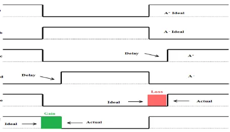
Fig-3. Pulse deviations (Afarulrazi and Zarafi, 2010)
Fig. 3 shows the effect of dead-Time. Trace 3a and 3b are the ideal pulse times; if applied, the
resulting fundamental voltage would be of the correct magnitude and phase. In trace 3c, A+
transitions from ON to OFF, but there must be a delay time before A- in trace d can turn from OFF
to ON. Likewise as A- in trace 3d transitions from ON to OFF, A+ in trace 3c must delay before it
can turn on.
Consider iu positive in trace 3e, as A+ transitions from ON to OFF, there is no reduction or gain to
the pulse time as compared to the ideal pulse time. As A+ transitions from OFF to ON, the pulse
time decreases from the ideal resulting in a deviation to the pulse time and an incorrect
fundamental voltage to the load.
When iu is negative as in trace 3f, A+ is held on longer than the ideal, resulting in an increase in
pulse time, and an incorrect fundamental voltage applied to the load. As A+transition from OFF to
ON, there is no reduction or gain to the pulse as compared to the ideal pulse.
Therefore, the real output voltage is greater (smaller) than its command as current is negative
(positive). Fig. 2 shows the phase voltage and current of the inverter output. As shown in Fig. 2, the
output voltage vo(t) is with distortion as compared to that without dead time (see waveforms A and
B). However, waveforms A and B cross each other at points P1 and P2. The output current io(t) is
also distorted at these two zero-crossing points, as shown in Fig. 2.
PROPOSED DEAD-TIME ELIMINATION SCHEME
A.
PWM Generator Without Dead Time
Fig. 3(a) shows the circuit of an inverter leg or half-bridge of converter. As shown in Fig. 3(a), an
antiparallel diode is connected with a power device. As the power device is off while the current
conduction continues, the antiparallel diode of its opposite power device provides the current path.
Therefore, there is no need to turn on the opposite power device during this turn-off period. Once
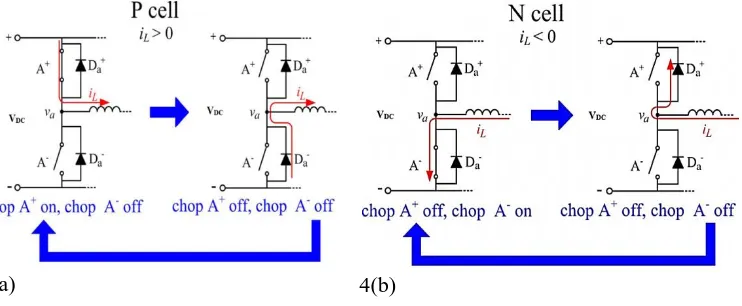
For example, when power device “A+” is turned off and the current direction retains, “Da-” will provide the current path when power device “A+” is turned off. Similar facts occur to power device “A−” and diode “Da+ ”. Therefore, power device “A+” and diode “Da- ” are defined as a “P” cell for positive current control (current flowing into the load side), as shown in Fig. 3(b). In addition, power device “A−” and diode “Da+” are defined as “N” cell [as shown in Fig. 3(b)], which conducts negative current.
Fig. 4 shows the PWM control without dead time. As shown in Fig. 4(a), once current is positive,
P-cell control is retained. Meanwhile, there is no PWM control signal for N-cell control.
Therefore, dead time is no longer required while guaranteeing no short through between positive
and negative dc links. Similarly, when current is negative, a PWM control signal is applied to N
cell only. Since there is no switching in the power device of P cell, dead time is no longer needed,
and no short through will occur.
Fig-4. PWM control based upon P cell and N cell. (a) P-cell control, iL >0. (b) N-cell control, iL <0.
4(a)
4(b)
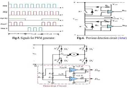
Fig. 5 shows the relationship between the chop signals and the control signals of converter without
dead time. The control signals can therefore be summarized as follows:
Chop A+ =chop • sign (iL) (1)
Chop A− =chop • sign (iL) (2)
As shown in (1) and (2), the required calculation is simple, and only slight modifications to the
PWM signal are required. Furthermore, the modifications can be realized by a digital controller.
For inverter control, the chop signal is changed to a PWM control signal. The PWM generator can
Fig-5. Signals for PWM generator. Fig-6. Previous detection circuit (Artur)
Fig-7. Proposed detection circuit.
B. Freewheeling-Current Polarity Detection Circuit WithoutIsolated Power
Fig. 6 shows the polarity detection of freewheeling current. The detection circuit requires two separate power sources, namely, “Vcc1” and “Vcc2,” as shown in Fig. 6. The required number of separate power sources is increased up to four for a three-phase inverter. These separate power
sources increase the difficulty for modularization of the detection circuit.
Fig. 7 shows the presented freewheeling-current polarity detection circuit. As shown in Fig. 7, only
one power source is required for the detection circuit for both single- and multiphase
inverter/converter. This special feature provides the potential of modularization of the detection
circuit. In Fig. 7, when iL >0, the terminal voltage becomes negative during the switch-off period,
as shown in Fig. 8(a). Similarly, during the switch-off period, the terminal voltage is positive and
greater than the dc-link voltage when iL<0, as shown in Fig. 8(b). Therefore, the terminal voltage
can be used to reflect the polarity of freewheeling current. Once the polarity of current is
determined, the control signals of converter/inverter can be generated by (1) and (2).
C. Freewheeling-Current Polarity Detection for Current WithMultiple Zero-Crossing Points
Under some conditions, e.g., small inductor of load, the output current polarity changes very
To deal with such ambiguous situation, the concept of average current is used as an assistance
index for the judgment of current polarity. Note that no real average value of load current is calculated. Once the period between “chop off” and zero crossing point
is slightly greater than
0
.
5(1
− D
)
ts
, the average current becomes negative, and the current polarity is changed.
The polarity change rule is therefore modified as follows. If
(3)
theniL,avg>0, and there is no change of current polarity. If
(4)
theniL,avg≤ 0, and the current polarity is changed, where tk= time interval between “chop off” and
zero-crossing point (k = 1, 2, 3, . . .).
The presented circuit for the dead-time elimination circuit
and the method are indeed effective. In the presented paper, dead time is not required, and the
power device (e.g., high-side power device) is turned on only when the antiparallel diode of its
counterpart (low-side power device) is conducting current. Therefore, the possibility for ZVS
seems dim.
Fig-8. Terminal voltage and PWM control signals without dead time. (a) iL>0 (b) iL <0
(a)
(b)
SIMULATION RESULTS
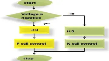
Fig. 10 shows the flowchart of the PWM generator without dead time. The “P”-cell control signal is switched on and off when current is negative. The polarity of freewheeling current is detected
regularly with a sampling frequency which is higher than the switching frequency to reduce the
detection error. In this section, the simulation performed by MATLAB software is carried out to
verify the proposed method. The schematic of the SPWM voltage source converter power stage
used for the simulation is shown in fig.11. The induction motor is chosen for the load of the
inverter. The simulations with both the conventional SPWM strategy with dead time and the
proposed method are carried out for comparison. Fig. 4 shows the simulation waveform of IL using
the conventional PWM strategy with dead time. From the simulation results it can be seen that the
output current is distorted. Fig. 12(b) shows the simulation waveforms using the proposed Method.
From Fig. 12(b) it can be seen that the switch commands to the upper and lower device of phase A,
A+ and A- are complementary and without dead time.
As shown in Fig. 11, the proposed method can detect the polarity, and the PWM control signals do
not require any dead time. Since the dead time for the presented method is eliminated, the current
distortion associated with dead time can be removed.
Fig-10. Flowchart of the implementation Fig-11. Gate pulses without dead-time
(a)
(b)
THD ANALYSIS
SPWM is an effective technique used for variable frequency drive applications. It utilizes dc bus
voltage more effectively
Fig-13. Simulation Diagram
and generates less THD in the Voltage Source Inverter. SPWM utilize a switching frequency to
spread the harmonics continuously to a wide band area so that the peak harmonics can be reduced
greatly. Simulation has been carried out by varying the modulation index between 0 and 1. Finally
performance of SPWM has been compared with and without dead time. The harmonic spectrum of
SPWM inverter with and without dead time is shown in fig. 14.
Fig-14.Harmonic spectrum of SPWM inverter
CONCLUSION
In this paper, a method was proposed to eliminate dead time in the SPWM controlled inverters.
Compared to the conventional method with dead-time, this method significantly reduces the output
distortion and THD and improves the performance of the load. The contributions of this paper
1) Propose a current polarity detection circuit which requires one power source only for
inverter.
2) Present the PWM control method without dead time based upon the proposed current
polarity detection circuit
3) Flexibleimplementation makes it an attractive option for VSI applications.
This method can be used in the voltage source PWM converter to improve the performance,
increase the reliability, and reduce the cost.