International Journal of Women’s Health
Dove
press
E x p E rt O p I n I O n
open access to scientific and medical research
Open Access Full text Article
role of uterine forces in intrauterine device
embedment, perforation, and expulsion
norman D Goldstuck1
Dirk Wildemeersch2
1Department of Obstetrics and
Gynaecology, Faculty of Medicine and Health Sciences, Stellenbosch University and tygerberg Hospital, Western Cape, South Africa;
2Gynecological Outpatient Clinic and
IUD training Center, Ghent, Belgium
Correspondence: norman D Goldstuck Department of Obstetrics and Gynaecology, Faculty of Medicine and Health Sciences, Stellenbosch University and tygerberg Hospital,
101 Francie van Zyl Street, Western Cape 7505, South Africa
tel +278 2341 8200 Email nahumzh@yahoo.com
Background: The purpose of this study was to examine factors that could help reduce primary perforation during insertion of a framed intrauterine device (IUD) and to determine factors that contribute in generating enough uterine muscle force to cause embedment and secondary perforation of an IUD. The objective was also to evaluate the main underlying mechanism of IUD expulsion.
Methods: We compared known IUD insertion forces for “framed” devices with known perfora-tion forces in vitro (hysterectomy specimens) and known IUD removal forces and calculated a range of possible intrauterine forces using pressure and surface area. These were compared with known perforation forces.
Results: IUD insertion forces range from 1.5 N to 6.5 N. Removal forces range from 1 N to 5.8 N and fracture forces from 8.7 N to 30 N depending upon device. Measured perforation forces are from 20 N to 54 N, and calculations show the uterus is capable of generating up to 50 N of myometrial force depending on internal pressure and surface area.
Conclusion: Primary perforation with conventional framed IUDs may occur if the insertion pressure exceeds the perforation resistance of the uterine fundus. This is more likely to occur if the front end of the inserter/IUD is narrow, the passage through the cervix is difficult, and the procedure is complex. IUD embedment and secondary perforation and IUD expulsion may be due to imbalance between the size of the IUD and that of the uterine cavity, causing production of asymmetrical uterine forces. The uterine muscle seems capable of generating enough force to cause an IUD to perforate the myometrium provided it is applied asymmetrically. A physical theory for IUD expulsion and secondary IUD perforation is given.
Keywords: IUD, insertion forces, removal forces, fracture forces, intrauterine pressure, intra-uterine surface area
Introduction
The intrauterine device (IUD) is a long-acting reversible contraceptive method with a favorable impact on reducing unwanted pregnancy. The IUD is usually well tolerated,
especially if it conforms to the uterine cavity.1 A not uncommon problem is that of
expulsion, which predisposes to unwanted pregnancy due to method failure. Expulsion may be related to a number of factors, including insertion technique and the relationship
between the size of the IUD and that of the uterine cavity.2–6 An uncommon problem
is that of uterine perforation, which is potentially serious and is variously reported
as occurring in every 1,000–2,500 insertions or with even greater frequency.7 The
precise cause of uterine perforation is not well understood. There is evidence that it is more common postpartum and during lactation. Inexperience, insertion technique,
International Journal of Women's Health downloaded from https://www.dovepress.com/ by 118.70.13.36 on 23-Aug-2020
For personal use only.
Number of times this article has been viewed
This article was published in the following Dove Press journal: International Journal of Women’s Health
Dovepress
Goldstuck and Wildemeersch
uterine states (lactation and postpartum), and instrumentation have all been suggested as causal factors.8–10 There is some
evidence that it may be primary (at the time of insertion) or secondary (at least 4 weeks or more after insertion has taken place). Secondary perforation may be due to a mismatch between the size of the device and the uterine cavity.3–5
Similarly, the problem of expulsion has been thought to be related to insertion technique, eg, lack of fundal placement of the IUD and not stabilizing the uterus with a tenaculum during placement. The type of IUD and the relationship of its size to that of the uterine cavity has also been suggested as a factor in IUD expulsion.3
Based on measuring the forces required for the insertion, removal, and fracture of IUDs and the forces the myometrium itself can generate, we tried to gain an insight into their role in IUD expulsion and how these forces are involved in primary embedment and secondary IUD perforation.
Background
During interval insertion of an IUD some force, often mini-mal, is required to place the device in the endometrial cavity. The force depends on several factors which have not been clearly differentiated. However, sometimes, the force required to insert an IUD can be significant. The force required to dilate the cervix either by using dilators or the IUD/inserter itself has been measured.11–13 Once the device is placed in
the endometrial cavity, the forces generated by myometrial contraction impact on the device. They have not been mea-sured in the presence of an IUD, but detailed measurement of intrauterine pressure, especially during dysmenorrhea, have been recorded.14–17 Endometrial cavity surface area has
also been measured.18,19 From these studies, it is possible to
calculate the uterine muscle force vector. The muscle force vector is the summation of all the uterine muscle forces to give a singular direction of force. It is analogous to the summated cardiac electrical muscle force that is represented on the electrocardiogram. It can be calculated for the myo-metrium using intrauterine pressure and surface area (see
Supplementary material).20 These calculations should help
to clarify the potential capability of the action of the force of myometrial muscle acting on an IUD in situ. The forces
required to remove an IUD have been measured,21,22 as have
the forces required to fracture an IUD23,24 and the forces for
failed insertion.25
The results obtained by experiment can be compared with the theoretical calculations to clarify the potential capability of the action of the force of myometrial muscle acting on an IUD in situ. They may also provide a better understanding
as to whether uterine muscle action alone can be responsible for IUD perforation and also give an explanation for how it causes device expulsion. Uterine forces may be determined using intrauterine pressure and surface area relationships alone. While Laplace’s law (the relationship of pressure, radius, and muscle wall tension) is informative for the preg-nant uterus where the radius of the uterine cavity is large relative to myometrial wall thickness, it is of limited use in the nonpregnant uterus where the radius is small relative to the myometrial wall thickness and will not be used.
Insertion forces
The forces acting against the insertion of an IUD are due to obstruction of passage of the device in the cervical canal, usually at the level of the internal cervical os, and frictional force resisting passage of the device.
The obstructive force is due to progression of the pre-senting surface area of the device.26 The frictional force is
the resistance to the device inserter tube as it passes along the cervical canal.26 The presenting diameter of the device
can be used to calculate the presenting surface area of the device.26 The larger the presenting diameter of the device,
the greater the force required to insert it because the present-ing surface area increases rapidly with increaspresent-ing radius
(see Supplementary material).26
retention forces
These are the forces that keep the IUD in place in the endo-metrial cavity, especially if it is fundally placed despite the downward myometrial forces attempting to displace (expel) it. The myometrial counterforces succeed in preventing expulsion for the most part, which is why the majority of IUDs remain in good position. These forces cannot be mea-sured directly. It is the breakdown of these forces (retention forces) that allows the IUD to be expelled either via the internal cervical os, embedded, or very much more rarely through the myometrium itself (perforation).
Fracture forces
These are the intrauterine forces that are capable of breaking IUDs which are in the uterine cavity.23,24 There are many
reports of IUD breakage, and the type of force needed to do this has been measured.23,27
Methods
We searched PubMed, Popline, and Google Scholar using the following search terms: “uterine forces”, “uterine pressure”, “uterine surface area”, “uterine pain”, “IUD expulsion forces”,
International Journal of Women's Health downloaded from https://www.dovepress.com/ by 118.70.13.36 on 23-Aug-2020
Dovepress IUD-related forces
“IUD fracture forces”, “IUD insertion forces”, and “uterine dilation forces for the nonpregnant uterus”. The aim of the search was to find the extreme of values related to these events. Since IUD perforation is a rare event, it is possible that it is due to a confluence of extreme conditions of uterine pressure and surface area and myometrial muscle tension. The physi-cal parameters that were obtained were to provide the basis for comparisons with known insertion, removal, and fracture forces obtained in other experimental studies.
Calculation of uterine forces was made using equations linking force, intrauterine pressure, and intrauterine surface area which were corrected for the parameters involved. The equations linking these involve static values for simplification and avoid the more complex equations associated with dynamic force vector calculus (see Supplementary material).
Results
Insertion and removal forces
The mean insertion forces required to insert the Copper-7®
(GD Searle and Co, High Wycombe, UK), Nova T 200® (Bayer,
Wuppertal, Germany), Progestasert® (Alza Corporation, Palo
Alto, CA, USA), and Multiload Copper (MLCu®; Multilan
AG, Dublin, Ireland) IUDs as well as Hegar dilators through the internal cervical os are given in Table 1. The forces required to insert these IUDs increase almost linearly with increasing inserter tube diameter.10,11 This is not true for
the Hegar dilators, which require much larger forces as the
diameter increases. This is because the IUD inserter tubes are compressible and because the surface area of the presenting end of the IUD inserter tube increases almost linearly over 3 mm to 6 mm.12,13 With increasing size over that, the
rela-tionship of diameter to presenting surface area of the Hegar dilators deviates substantially from linearity, ie, increasing diameter produces a significantly larger relative surface area and requires significantly more force for insertion.
The obstructive force to the IUD is related to the surface area of the presenting part. The frictional force opposing IUD insertion is minimal due to the smooth surface of the IUD inserter tube and lubrication of the cervical canal, and will not be considered further.26 The force required to insert an
IUD in vivo is generally 1.5 N to 6.5 N, depending on type in
nulliparous and low parity women.11 In multiparous women,
it is consistently at the lower end of that range.11
Even for unsuccessful insertions, the mean forces produced were 4–7.6 N. Increased force usually results in “bowing” of the inserter tube if there is an obstruction at the cervical canal.25 In in vitro testing using fresh hysterectomy
specimens,11 it was possible to perforate the uterus with a
metal sound by applying forces of 20.7–28.4 N depending on anatomical site (perforation was easiest near the uterotu-bal junction) and thickness of the myometrium. It was also possible to perforate the uterus with the Dalkon Shield®
(AH Robins, Richmond, VA, USA) inserter, which is made of a stiff and rigid plastic, using 31.6 N of force,11 but not
with the inserter tubes of the other devices.
This was in general agreement with the perforation forces for the Dalkon Shield obtained by Horbelt et al who concluded that insertion forces are significantly lower than the forces needed for perforation of the Dalkon Shield, and IUD perforation as a result of transmigration of the IUD is a possibility due to uterine muscle action.28 They found that the mean insertion force of the
standard Dalkon Shield device was 6.05 lbs force (26.9 N) and the perforation force was 9.95 lbs force (44.3 N). They found the force required to perforate the uterus using the applicator only was 12.4 lbs force (55.18 N) to 13.09 lbs force (58.02 N) depend-ing on uterine position.28 This is similar to the Dalkon Shield
perforation forces of the later study.11 The perforation forces
with the metal sound and Dalkon Shield inserter correspond to a pressure of 2–3 N per mm2 of myometrial surface area.11 The
narrower the diameter of the part of the IUD pressing against the myometrial wall, the lower the perforating force required (as the pressure against the wall will be greater).
There were two studies that measured the force required to remove an IUD from the uterus.21,22 The force required to
remove various IUDs varies from ,1 N to 5.8 N depending on
Table 1 Forces required to insert an intrauterine device and to dilate the cervical canal
Study Dilator (mm) Mean
force (N)
Anthony et al12 Hegar 3
Hegar 4 Hegar 5 Hegar 6 Hegar 7 Hegar 8
2.45 3.43 8.33 22.05 40.42 41.65 nicolaides et al13 Hegar 3
Hegar 4 Hegar 5 Hegar 6 Hegar 7 Hegar 8
1.3 1.4 3.4 12.3 24.7 32.4 Goldstuck11 Copper-7®* 3.07
nova t 200®* 3.6
progestasert®* 6.1
Multiload Copper®◊ 6.5
1.5 2.13 6.5#
4.04
Notes: *presenting diameter of intrauterine device inserter tube; #one evaluation
only; ◊presenting diameter for all devices in the series (excluding side arms).
Copper-7, GD Searle and Co (High Wycombe, UK). nova t 200, Bayer, (Wuppertal, Germany). progestasert, (Alza Corporation, palo Alto, CA, USA). Multiload Copper (MLCu), (Multilan AG, Dublin, Ireland).
International Journal of Women's Health downloaded from https://www.dovepress.com/ by 118.70.13.36 on 23-Aug-2020
Dovepress
Goldstuck and Wildemeersch
the IUD (Table 2). These forces do not represent the maximum in utero force that a device can resist, merely the force to pull the device (removal force) out of the endometrial cavity and through the external cervical os. In general, it appears that devices con-forming to the uterine cavity shape are associated with higher removal forces.22 This is because devices that do not conform
to the uterine cavity have poorer anchoring mechanisms. This may help to explain why devices that conform to the size of the uterine cavity are more resistant to being expelled.
IUD fracture forces
The forces required to break the transverse arm of the IUD from the horizontal arm have been determined.27 This was done
for both used and unused devices. The mean force required
to rupture a new or used Copper-7 IUD was 30.4±9.58 N,
while the mean forces required to rupture the Nova T 200 IUD were 16.8 N for used devices and 6.8 N for unused. The MLCu 250 device required a mean force of 15.7 N to rupture unused devices and 8.7 N to rupture used devices. Spontaneous rupture of a MLCu 250 IUD has been reported occasionally to the manufacturers.29 More recently, a report of spontaneous
intrauterine rupture of a Copper T 380A IUD (ParaGard®; Teva
Pharmaceutical Industries Ltd, Petach Tikva, Israel)30 and of a
Mirena® IUD (Bayer) have been reported.31 We do not know
the force required to rupture a Copper T 380A IUD, but since the frame of the Mirena is the same as that of the Nova T 200, we have direct evidence that the uterus can generate the 16 N of force required to rupture the frame of the Mirena IUD.
Calculated uterine forces
In order to calculate the total uterine force produced for a given time, we need to know the intrauterine pressure and surface area, as was previously explained (a detailed explanation of the calcu-lations is given in the Supplementary material). The recalcu-lationship
of uterine force for a given intrauterine pressure for three values of surface area is shown in Figure 1. The calculated total force is the sum of all the prevailing force vectors. Normally, the resultant intrauterine force vector is from the fundus to the cer-vix (Figure 2). This is true because the direction of unattached intrauterine contents is normally through the cervix, eg, IUDs or menstrual blood. Unusually, the direction of intrauterine forces may be aberrant, eg, retrograde passage of endometrial products possibly leading to endometriosis.16
Endometrial cavity surface area has been measured indi-rectly and diindi-rectly,18,19 the usual values being 600–1200 mm2.
Intrauterine pressure in the nonpregnant uterus has been studied using various techniques.32 In general, it tends to be highest in
the late luteal phase of the cycle and lowest in the early follicular phase. Basal pressure is highest in the periovulatory phase of the cycle. Retrograde uterine contractility (if present) is also highest at the time of ovulation.16 Placement of an IUD itself, however,
does not increase intrauterine pressure.33 During episodes of
dysmenorrhea, intrauterine pressures of up to 300 mmHg and above have been recorded.14 Intrauterine pressures of up to
100 mmHg are usually not associated with symptoms.32
Pressures of this magnitude, especially if the endometrial cavity surface area is over 1,000 mm2, will result in total
Table 2 Forces required to remove an intrauterine device
Study Type of IUD Removal
forces (N) mean ± SD (range)
Comments
D’Souza
et al21 Gynet380S® 2.2±1.46
Kurz22 Multiload Copper® 250
Copper-7® 200
Copper t® 200
Copper t 200 (adapted)
5.4–5.8 2.6–3.8 1.0–1.7 1.6–2.6
Cross arm 15–28 mm depending on size of uterine cavity
Notes: Gynet380S®, Ortho pharmaceutical Corp. (raritan, nJ, USA). Multiload
Copper® 250, (Multilan AG, Dublin, Ireland). Cop per-7®, GD Searle and Co (High
Wycombe, UK). Copper t® 200, Ortho pharmaceutical Corp. Copper t 200
(adapted), Ortho pharmaceutical Corp.
Abbreviations: IUD, intrauterine device; SD, standard deviation.
0 50 100 150 200
Pressure (mmHg)
Force (N)
250 300 350 Surface area
600 mm2 900 mm2 1,200 mm2 5
10 15 20 25 30 35 40 45 50 55
Figure 1 Myometrial force (n) produced by a given intrauterine pressure (mmHg) for three values of endometrial cavity surface area.
International Journal of Women's Health downloaded from https://www.dovepress.com/ by 118.70.13.36 on 23-Aug-2020
Dovepress IUD-related forces
uterine force of sufficient magnitude to produce expulsion, embedment, or perforation of an IUD (Figure 1). We have direct clinical evidence that the uterus can produce forces of 16–20 N because we know that intrauterine fracture of IUDs requires this kind of force. By calculating the forces the uterus can produce using pressure and surface area, we know the uterus is theoretically capable of generating forces of around 50 N, which is sufficient to produce uterine perforation even after the IUD is confirmed to be correctly placed using ultrasound. This suggests that there may be occasions where the provider of the IUD is not responsible for its perforation of the uterine cavity. This conclusion has profound medicolegal implications.
Discussion
The nature of IUD perforation, whether primary or secondary or both, has been the subject of discussion for many years.34,35
This study suggests that both are possible. The forces required to perforate the myometrium are greater than the forces needed to insert an IUD if the inserter tube is flexible, because it will simply “bow” if it comes up against the myometrial wall.25 If an Allis forceps is applied to the cervix rather than
a single-toothed tenaculum to stabilize the uterus, it will generally slip off after application of 6–8 N of force.11 This
means it will act as a safety valve and not allow perforation on insertion as a single-toothed tenaculum might. This is not true for the inflexible Dalkon Shield inserter (or any other inflexible inserter) and unknown for the relatively flexible Mirena inserter.11 A metal sound is, however, easily capable of
perforating the myometrium, especially at its most vulnerable area around the uterotubal junction, with application of 20 N force.11 This suggests that sounding the uterus before IUD
insertion, when required, should preferably be performed with a flexible plastic disposable sound, with care taken not to use excessive force.
The higher the force required to insert an IUD, the more pain sensations are provoked.36 A larger oval presenting end
of 5–7 mm could pass without as much force as a round one because the internal cervical os is often oval-shaped or may become oval-shaped when stretched. This allows lower insertion forces for anatomical reasons. Figure 3 shows the presenting end of the T-shaped Femilis® levonorgestrel-releasing intrauterine
system (Contrel Europe NV, Ghent, Belgium). In this case, insertion will usually not cause much resistance during the insertion procedure.37 Experience suggests that the tissue on the
lateral sides of the internal ostium stretches more easily than the tissue anteroposteriorly. Advanced hysteroscopes are also oval-shaped to allow hysteroscopy to be done in the office. Therefore, a round instrument of 5 mm will usually cause pain because of stretching of all sensitive muscle fibers around the internal os.12,13 This is a solution, at least in part, to the insertion forces
problem. Perforation of the uterus at the time of IUD insertion may be operator-dependent7 and may be more likely if the uterus
is acutely anteflexed or retroflexed and is not straightened before insertion. Use of a tenaculum with 2 N of force can reduce the uterocervical angle from 75 degrees to 10 degrees38 by applying
traction and straightening the uterine axis, and may help prevent lower uterine perforation. Insertion in lactating women, even beyond 6 weeks after delivery, was shown to be an important risk factor.8,10,35 An atrophic uterus (caused by long-term use of
a depot injectable) is also a risk factor because the fundal myo-metrium may become thin. Except in cases of uterine atrophy and in postpartum lactating women,10 the forces required to
cause perforation at insertion of the IUD (primary perforation) are higher than the forces needed to insert an IUD.28
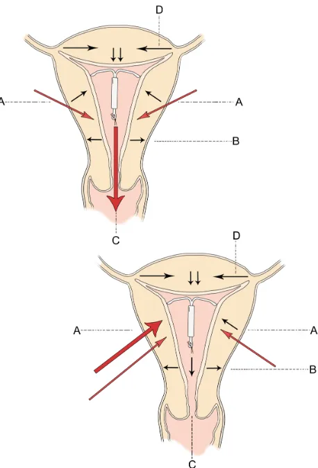
Figure 2 Direction of uterine forces in the normal intrauterine device containing uterus are given at (A–D) in the top diagram.
Notes: Depending on the time of the cycle (and at basal pressures), any direction may be dominant. At higher pressures, the fundus to cervix force at (C) is usually dominant and the counterforces at (A) hold the IUD in place. High pressure asymmetrical forces at position (A) in the bottom diagram push the intrauterine device from left to right and towards the fundus so that it perforates at the uterotubal junction.
Abbreviation: IUD, intrauterine device.
International Journal of Women's Health downloaded from https://www.dovepress.com/ by 118.70.13.36 on 23-Aug-2020
Dovepress
Goldstuck and Wildemeersch
There is strong evidence for secondary perforation, ie, the so-called “migrating device”. This occurs when an IUD which is known to be in situ 8 weeks or more after insertion is later found to be in an ectopic position.39 Since IUDs are inert,
they do not migrate but are driven by the force of myometrial
contractions into the abnormal location. The question arises as why this applies to some IUDs and not to the majority. In the case of the MLCu device, at least 50% of IUD perfora-tions occurred late (after 3 months up to more than 2 years).40
IUDs must be driven by the force of myometrial contractions into the abnormal location (Figure 4). If the IUD is too large for the uterine cavity, and possesses pointed tips, penetration of the IUD in the uterine wall occurs usually slowly until eventually perforation occurs (Figure 5). Penetration of the wall causing embedment leads to pain complaints and abnor-mal bleeding, and is probably far more frequent than slow perforation.41 Most IUDs remain in situ even if the uterus is
generating forces in excess of the forces required for remov-ing a device, and some are expelled. We thus need to explain how IUDs remain in situ if the uterus is generating forces in excess of the forces required for removing a device.
The key to understanding this problem is to remember that the summated force is a multivector quantity (ie, it is multidirectional). That being the case the total uterine force produced consists of forces simultaneously going from fun-dus to cervix, cervix to funfun-dus, and tangentially to the main axis of force (Figure 2). While the resultant vector force may be in a given direction there are many minor forces acting in different directions from the resultant vector. The IUD remains in place because the fundal force pushing the device downwards (Figure 2, force “C”) is functionally matched by upward forces of the myometrial promontory (Figure 2, force “A”). Note that if the device is placed at the fundus it escapes being exposed to the full weight of the downward forces at “A” since some of them act downwards at or below Figure 3 The figure shows an oval shaped internal cervical os.
Note: the inserter tube and folded arms will automatically rotate (arrow) and adapt to the shape of the os to find the entry of least resistance, usually in the latero-lateral direction.
Figure 4 Extreme forces can act on the intrauterine device (eg, Multiload Cu-IUD [MLCu®; Multilan AG, Dublin, Ireland]) causing somersaulting and predisposing to
expulsion or perforation.
Note: this is the end result of progressive clockwise or anticlockwise asymmetric uterine rotation forces.
Abbreviation: IUD, intrauterine device.
Figure 5 Secondary perforation of one extremity of the transverse arm of an intrauterine device close to the uterotubal junction; the other extremity is about to perforate (arrow).
Note: this type of secondary perforation is due to asymmetrical uterine forces and cannot be produced on insertion.
International Journal of Women's Health downloaded from https://www.dovepress.com/ by 118.70.13.36 on 23-Aug-2020
Dovepress IUD-related forces
could be anatomical or physiological. Normally, the majority of myometrial fibers are found in the fundal region and become sparser, being replaced by connective tissue, closer to the lower uterine segment. Perhaps there is a distortion of this arrangement in IUD users who experience perforation. The knowledge that uterine muscle can generate enough force to drive an IUD through its walls has significant implications. It can be stated with a fair degree of certainty that the uterus alone may be responsible for perforation in some instances and that the provider who inserted the device is not culpable. This is especially true if the perforation occurred 8 weeks or more post-insertion.
While secondary perforation has long been suspected, our paper demonstrates a definitive physical and physiological basis for the phenomenon by showing that uterine muscle can provide the power necessary for secondary perforation.
Conclusion
Perforation is a rare but serious complication of IUD use. There is considerable diversity of opinion as to whether it occurs only at the time of insertion and also as a secondary phenomenon, ie, after the device is already in place. In order for a properly placed device to leave the endometrial cavity, the myometrium must be able to exert sufficient force to drive the device through the uterine wall. Prior to perforation, the IUD projections can penetrate the muscle wall and cause damage and side effects which are a warning sign. In these cases, three-dimensional sonography is very useful to deter-mine the exact position of the IUD, including the transverse arms. Two-dimensional sonography is much less suitable for seeing the transverse arms. Expulsion is a not uncommon complication of IUD use and may cause the device to fail. Figure 6 3D ultrasonography of an abnormally located paraGard® intrauterine
device (left) and Mirena® levonorgestrel intrauterine system (right) causing bleeding
and pain.
Notes: the fundal transverse dimension in these cases is only approximately 2 cm. the fundal width shown in the picture on the right is 19.56 mm. Severe disproportion causes expulsion, embedment and sometimes secondary perforation as a consequence of severe uterine forces. Markers indicate maximum uterine cavity width. paraGard (teva pharmaceutical Industries Ltd, petach tikva, Israel). Mirena (Bayer, Wuppertal, Germany).
the level of the IUD stem. This explains why devices which are placed at or as close to the fundus as possible are more resistant to expulsion. For example, if the transverse arm of a T-shaped IUD is unable to unfold completely in the upper part of the cavity (Figure 6) because of a too small uterine cavity transverse diameter, downward displacement and expulsion is likely to occur, or embedment and secondary perforation, as a consequence of uterine contractile forces.
The cliché of “fundal seeking”, with which some manu-facturers have described their devices may be reasonably
accurate (eg, the Flexi-T300®, Prosan SA, and the Femilis
levonorgestrel-releasing intrauterine system).42 This would
be especially true where the device is placed close to the fundus and where the arms sit snugly above the myometrial promontory (Figure 7). Expulsion is therefore a failure of one or both sides of the uterine muscle promontory to pro-vide enough effective counterforce to the main fundus to cervix force vector. This is much more likely if the device does not open properly, which is usually due to dimensional incompatibility between the device and the uterine cavity.
It could be that perforation, like many other abnormal physical events, is explained by asymmetry (Figure 2, lower diagram). In this case, the resultant uterine muscle force vec-tor is directed laterally or posteriorly with significant force (30 N+) to drive the IUD out of the uterine cavity and into a contiguous structure, eg, the bladder or abdominal cavity.39
The cause of asymmetric muscle forces is not apparent, but
Figure 7 t-shaped Femilis® levonorgestrel intrauterine system (Contrel Europe
nV, Ghent, Belgium) with transverse arm of either 24 mm or 28 mm, showing perfect fit in the fundus of the uterus.
Note: Expulsion have been less than one per 100 per year in multicenter studies.37
International Journal of Women's Health downloaded from https://www.dovepress.com/ by 118.70.13.36 on 23-Aug-2020
Dovepress
Goldstuck and Wildemeersch
Ensuring fundal placement and using an IUD that conforms to the transverse width of the uterine cavity in the fundus will help the device to resist myometrial expulsive forces.
Clinical trials suggest a one-dimensional frameless IUD/intrauterine system is most likely to be success-ful, because it is theoretically capable of adapting to asymmetrical myometrial forces (Figure 8). This can be demonstrated using topology, ie, the study of complicated geometrical surfaces. The intracavitary forces act below the anchor mechanism and largely below the linear shape of the frameless devices, which may allow them to adapt to the highly distorted uterine cavity shape changes and pressures which severe asymmetrical forces could pro-duce. In terms of IUD tolerance and continuation of use, from a practical point of view, the worst case is to insert an IUD which is too big for the uterine cavity. To be well tolerated, an IUD should cause a minimum of distortion of the endometrial cavity during the maximum degree of the
contraction phase.7 In theory, a one-dimensional frameless
IUD/intrauterine system probably provokes the least reac-tion from the uterus and is likely to be universally tolerated, as clinical trials suggest.43
Disclosure
DW has been involved in the optimization of innovative drug delivery systems for use in the uterus. He is currently
an advisor in devising new concepts in controlled release for contraception, gynecological treatment, and prevention of infectious diseases. NDG reports no conflict of interest in this work.
References
1. Wildemeersch D. IUD/IUS designs that do not fit may significantly
contribute to early discontinuation – a commentary. Eur J Contracept
Reprod Health Care. 2011;16:135–141.
2. Hasson HM. Clinical studies of the Wing Sound II metrology device.
In: Zatuchni GI, Goldsmith A, Sciarra JJ, editors. Intrauterine
Contraception:Advances and Future Prospects. Philadelphia, PA, USA: Harper and Row; 1984:126–141.
3. Kurz KH. Cavimeter uterine measurements and IUD clinical correlation.
In: Zatuchni GI, Goldsmith A, Sciarra JJ, editors. Intrauterine
Contraception:Advances and Future Prospects. Philadelphia, PA, USA: Harper and Row; 1984:142–162.
4. Kamal I, Hefnawi F, Ghonheim M, Talant M, Abdalla M. Dimensional and architectural disproportion between the intrauterine device and the
uterine cavity: a cause of bleeding. Fertil Steril. 1971;22:514–521.
5. Goldstuck N. Assessment of uterine cavity size and shape: a systematic review addressing relevance to intrauterine procedures and events. Afr J Reprod Health. 2012;16:129–138.
6. Goldstuck ND. The relationship of IUD dimensions to event rates. Contracept Deliv Syst. 1982;3:103–105.
7. Tatum HJ, Connell EB. Intrauterine devices. In: Filshie M,
Guillebaud J, editors. Contraception:Science and Practice. London,
UK: Butterworths; 1989.
8. Van Houdenhoven K, van Kaam KJAF, van Grootheest AC, Salemans THB, Dunselman GAJ. Uterine perforation in women using
a levonorgestrel-releasing intrauterine system. Contraception. 2006;73:
257–260.
9. Heartwell SF, Schlesselman S. Risk of perforation among users of
intrauterine devices. Obstet Gynecol. 1983;61:31–36.
10. Goldstuck ND, Holloway G. IUD insertion forces: effects of recent
childbirth and lactation. Adv Contracept. 1988;4:159–164.
11. Goldstuck ND. Insertion forces with intrauterine devices: implications
for uterine perforation. Eur J Obstet Gynecol Reprod Biol. 1987;25:
315–323.
12. Anthony GS, Fisher J, Coutts JR, Calder AA. Forces required for surgical dilatation of the pregnant and non-pregnant human cervix. Br J Obstet Gynaecol. 1982;89:913–916.
13. Nicolaides KH, Welch CC, McPherson MB, Johnson IR, Filshie GM. Lamicel: a new technique for cervical dilatation before first trimester
abortion. Br J Obstet Gynaecol. 1983;90:475–479.
14. Milsom I, Andersch B. Intrauterine pressure and serum ibuprofen: observations after oral administration of 400 mg ibuprofen to
a patient with primary dysmenorrhoea. Eur J Clin Pharmacol.
1985;29:443–446.
15. Liedman R, Skillern L, James I, McLeod A, Grant L, Akerlund M.
Validation of a test model of induced dysmenorrhoea. Acta Obstet
Gynecol Scand. 2006;85:451–457.
16. Bulletti C, de Ziegler D, Polli V, Diotallevi L, Del Ferro E, Flamigni C.
Uterine contractility during the menstrual cycle. Hum Reprod. 2000;
15 Suppl 1:81–89.
17. Czekanowski R. Die Abhaengigkeit von Volumen un Druck in der nicht schwangeren menschlichen. [In-vitro studies into interdependence of
volume and pressure in non-pregnant human uterus]. Zentralbl Gynakol.
1980;102:129–137. German.
18. Tejuja S, Malkani PK. Clinical significance of correlation between size of the uterine cavity and IUCD: a planimeter hysterogram technique. Am J Obstet Gynecol. 1969;105:620–627.
19. Ismail AA, Anwar MY, Kesk SM, Azay SM, Gaweesh S, Toppozada MK. Uterine geometry by Wing sound and hysterography versus direct
measurements. Adv Contracept. 1987;3:237–243.
Figure 8 Frameless copper and drug delivery systems occupy limited space in the uterine cavity and have no transverse arms, eliminating embedment and secondary perforation of the uterine wall.
Notes: Arrows indicate uterine cavity width. Framed intrauterine devices that do not adapt to the width of the uterine cavity, or with too long transverse arms, are likely to become embedded, if not expelled, and could perforate the uterine wall in the presence of asymmetrical forces. the anchor is highly visible in the fundal muscle in both pictures.
International Journal of Women's Health downloaded from https://www.dovepress.com/ by 118.70.13.36 on 23-Aug-2020
Dovepress IUD-related forces
20. Sharma AK. Text Book of Vector Calculus. New Delhi, India: Discovery
Publishing House; 2006.
21. D’Souza RE, Bounds W, Guillebaud J. Comparative trial of the force
required for, and pain of, removing GyneFix® versus Gyne-T380S®
following randomised insertion. J Fam Plann Reprod Health Care.
2003;29:29–31.
22. Kurz KH. Role of retention in avoiding expulsion of IUDs- measuring
devices for basic research. Contracept Deliv Syst. 1982;3:107–116.
23. Goldstuck ND. IUD fracture mechanism. Contraception. 2014;89:328.
24. Wilson S, Tan G, Baylson M, Screiber C. Controversies in family
planning: how to manage a fractured IUD. Contraception. 2013;88:
599–603.
25. Goldstuck ND. Bowing forces with IUD inserters in vitro: reference to
difficult IUD insertions. Clin Reprod Fertil. 1987;5:173–176.
26. Giancoli DC. Physics. 6th ed. Upper Saddle River, NJ, USA: Pearson
Prentice Hall; 2012.
27. Goldstuck ND, Hofmeyr GJ, Sonnendecker EW, Butchart A. In vitro study of fracture forces associated with the Copper T, Nova T and MLCu
250/375 intrauterine devices. Contraception. 1990;41:583–589.
28. Horbelt DV, Roberts DK, Anderson HW. Studies in translocation:
Dalkon shield insertion, perforation and migration. J Kans Med Soc.
1979;80:323–326.
29. Custo G, Saitto C, Cerza S, Cosmi EV. Intrauterine rupture of a
Multiload Cu 250 intrauterine device: report of a case. Adv Contracept.
1988;4:217–220.
30. Sinha P, Pradhan A, Diab Y. Expulsion of part of a spontaneously broken
IUD. J Obstet Gynaecol. 2004;24:837–838.
31. Jindal S, Sharma SS, Ikorni A. Spontaneous breakage and expulsion of a stem fragment of levonorgestrel intrauterine system (Mirena) following
duplicate insertion. Arch Gynecol Obstet. 2009;279:95–97.
32. Braaksma JT, Janssens J, Eskers TKAB, Hein PR. Accurate pres-sure recording in the non-pregnant human uterus. A comparison
of open and closed tip catheters. Eur J Obstet Gynaecol. 1971;6:
195–206.
33. Macedo-Costa LF, Pinto-Dantas CA, Darze E, De Souza O. The effect of
the IUD on the intrauterine pressure of the human uterus. Int J Gynecol
Obstet. 1971;9:192–202.
34. Zakin D, Stern WZ, Rosenblatt R. Complete and partial uterine perforation and embedding following insertion of intrauterine devices. I. Classification, complications, mechanism, incidence and missing
string. Obstet Gynecol Surv. 1981;36:335–353.
35. Caliskan E, Ozturk B, Dilbaz O, Dilbaz S. Analysis of risk factors
associated with intrauterine perforation by intrauterine devices. Eur J
Contracept Reprod Health Care. 2003;8:150–155.
36. Goldstuck ND. A comparison of the initial pain response following insertion of the Copper 7 and combined Multiload Copper 250 IUDs. Contracept Deliv Syst. 1982;2:295–301.
37. Wildermeersch D, Janssens D, Andrade A. The Femilis® LNG-IUS:
contraceptive performance – an interim analysis. Eur J Contracept
Reprod Health Care. 2009;14:103–110.
38. Johnson N, Bromham DR. Effect of cervical traction with a
ten-aculum on the uterocervical angle. Br J Obstet Gynaecol. 1991;98:
309–312.
39. Eke N, Okpani AO. Extrauterine translocated contraceptive device: a presentation of five cases and revisit of the enigmatic issues of
iatrogenic perforation and migration. Afr J Reprod Health. 2003;7:
117–123.
40. Harrison-Woolrych M, Ashton J, Coulter D. Uterine perforation on intrauterine device insertion: is the incidence higher than previously
reported. Contraception. 2003;67:53–56.
41. Benacerraf BR, Shipp TD, Bromley B. Three-dimensional ultrasound detection of abnormally located intrauterine contraceptive devices which
are the source of pelvic pain and abnormal bleeding. Ultrasound Obstet
Gynecol. 2009;34:110–115.
42. Flexi-T. [homepage on the Internet] Prescribing information. Prosan International BV, Arnhem, the Netherlands; 2005. Available from http:// www.trimedic-inc.com/flexi-t_iud_advantage.html. Accessed July 8, 2014.
43. Wildemeersch D, Pett A, Jandi S, Hasskamp T, Rowe P, Vrijens M. Precision intrauterine contraception may significantly increase continu-ation of use: a review of long-term clinical experience with frameless
copper-releasing intrauterine contraception devices. Int J Womens
Health. 2013;5:215–225.
International Journal of Women's Health downloaded from https://www.dovepress.com/ by 118.70.13.36 on 23-Aug-2020
International Journal of Women’s Health
Publish your work in this journal
Submit your manuscript here: http://www.dovepress.com/international-journal-of-womens-health-journal
The International Journal of Women’s Health is an international, peer-reviewed open-access journal publishing original research, reports, editorials, reviews and commentaries on all aspects of women’s healthcare including gynecology, obstetrics, and breast cancer. The manuscript management system is completely online and includes
a very quick and fair peer-review system, which is all easy to use. Visit http://www.dovepress.com/testimonials.php to read real quotes from published authors.
Dovepress
Dove
press
Goldstuck and Wildemeersch
Supplementary material
Mathematical glossary
a. The presenting surface area (psa) of an IUD inserter is related to the diameter by the formula π r2, where r is the radius,
ie, the diameter/2.
Psa = (diameter/2)2×π
b. Intrauterine force is a vector quantity, ie, it has both magnitude and direction. Intrauterine pressure is a scalar quantity, ie, it has magnitude only.
Pressure = force/unit area, and therefore, Force = pressure × unit area
The force in Newtons (N) of uterine contraction can be calculated from intrauterine pressure and intrauterine (endome-trial cavity) surface area.
Pressure is usually measured in Pascals and a Pascal = N/meters2 or N = Pascal × meters2
If intrauterine pressure is measured in mmHg and endometrial cavity surface area is measured in mm2, then as
1 kPascal =7.5 mmHg
and
mmHg = kPascals × 103 = 7 5. Pascals
and
mm2= meter2× 10-6
Intrauterine force (N) = mmHg/7.5 × 103× mm2× 10-6
= mmHg/7.5 × 10-3× mm2
Calculation of uterine force in Newtons is a summation of the overall forces related to a particular pressure and surface area. It does not provide the direction or directions of the component forces, and some of the forces may act in different directions and in opposition.
c. 1 lb force =4.4482 Newtons.
International Journal of Women's Health downloaded from https://www.dovepress.com/ by 118.70.13.36 on 23-Aug-2020


![Figure 4 Extreme forces can act on the intrauterine device (eg, Multiload Cu-IUD [MLCu®; Multilan AG, Dublin, Ireland]) causing somersaulting and predisposing to expulsion or perforation](https://thumb-us.123doks.com/thumbv2/123dok_us/8394473.1385624/6.612.61.284.385.657/intrauterine-multiload-multilan-ireland-somersaulting-predisposing-expulsion-perforation.webp)


