© 2015, IRJET.NET- All Rights Reserved
Page 2327
Modelling of Fuzzy Generic Power System Stabilizer for SMIB System
D.Jasmitha
1, Dr.R.Vijayasanthi
2PG Student, Dept. of EEE, Andhra University (A), Visakhapatnam, India1
Assistant Professor, Dept. of EEE, Andhra University (A), Visakhapatnam, India2
Abstract
Modern power systems consist of several generators working synchronously to meet the power demand. For reliability of these systems, stability must be ensured in case of faults within the system. Faults within a system induce electro-mechanical oscillations of electrical generators. These oscillations, also called power swings must be effectively damped to maintain the system stability. In an attempt to reduce the system oscillations, Power System Stabilizers (PSS) are used to add damping by controlling the excitation system. A well tuned PSS can effectively improve power system dynamic stability. The Power System Stabilizers are mainly designed to stabilize the local and inter-area mode power system oscillations. The Power System Stabilizer (PSS) is a device that improves the damping of generator electro-mechanical oscillations. Stabilizers have been employed on large generators to improve stability constrained operating limits. However it results into poor performance under various loading conditions when implemented with Conventional PSS. Therefore the need for fuzzy logic PSS arises.
In the present work, an attempt was made to provide systematic approach for stabilizing a Single Machine Infinite Bus (SMIB) system with a non-linearity i.e., Generation Rate Constraint (GRC) using generic power system stabilizer with fuzzy logic controller and is compared with Conventional PSS and Generic Power System Stabilizer. The GRC would influence the dynamic responses of the system significantly and lead to larger overshoot and longer settling time. Simulation results are presented under wide range of operating conditions. Results presented in the thesis demonstrate that the proposed Controller gives better performance when compared to Conventional PSS and Generic Power System Stabilizer.
Key Words: Power System Stabilizers (PSS), Generic Power System Stabilizer (GPSS), Generator Rate Constraint (GRC), Fuzzy
Generic Power System Stabilizer.
---***---I.INTRODUCTION
The stability of power systems is one of the most important aspects in electric system operation. This arises from the fact that the power system must maintain the frequency and voltage levels, under any disturbance, like a sudden increase in the load, loss of one generator or switching out of a transmission line, during a fault [1]. One of the major problems in the power system operation is related to the small-signal oscillatory instability caused by the insufficient natural damping in the system. The most cost-effective way of countering this instability is using the auxiliary controllers called Power System Stabilizers (PSS), to produce additional damping in the system [2],[3]. During the changes in the operating conditions, the oscillations of small magnitude and low frequency often persists for a long period of time and in some cases even present limitations on the power transfer capability. A Power System Stabilizer (PSS) is designed to damp the low frequency oscillations of the power system. The Power System Stabilizer PSS is used to damp the generator rotor oscillations by controlling its excitation using the auxiliary stabilizing signals.
An inter-connected power system, depending on its size, has hundreds to thousands of modes of oscillation. In the analysis and control of the system stability, two distinct types of system oscillations are usually recognized. One type is associated with units at a generating station swinging with respect to the rest of the power system. Such oscillations are referred to as the local plant mode of oscillations. The frequencies of these oscillations are typically in the range of (0.8-2.0) Hz. The second type of oscillations is associated with the influenced by the PSS include torsional modes and control modes such as the exciter mode associated with the excitation system and the field circuit [4].
II. MODELLING OF SINGLE MACHINE INFINITE
BUS SYSTEM
© 2015, IRJET.NET- All Rights Reserved
Page 2328
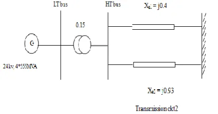
A Single Machine Infinite Bus System (SMIB) isconsidered for the present investigations. The system of study is the one machine connected to infinite bus
system through a transmission line having resistance re
and inductance xe shown in Figure 2.1
Figure 2.1 Single Machine Infinite Bus System
The generator is modeled by transient model, according to the following equations. All system data can be found in
The investigation of the behavior of the generator can be done in two ways. In the first case the inputs are the infinite bus voltage that are transformed into rotating frame, the field voltage and the mechanical torque. The machine terminal and infinite bus voltages in the terms of the d and q components are
Ẽt = vd + jvq --- (2.8)
Ẽb = vbd + jvbq --- (2.9)
Referring to Figure 2.1, the network constraint equation is
Ẽt = Ẽb + (re+jxe) --- (2.10)
----
(2.11)
Resolving into d and q components gives
--- (2.12)
variables , , and infinite voltage:
--- (2.14)
--- (2.15)
The stator voltage equations (2.1) and (2.2), without the external RL line parameters, are used to compute the terminal voltage of the generator within the block “stator winding”.
A Single Machine Infinite Bus (SMIB) system is considered for the present investigations. A machine connected to a large system through a transmission line may be reduced to a SMIB system by using Thevenin’s voltage (infinite bus voltage). The Thevenin equivalent impedance shall henceforth be referred to as equivalent
impedance (i.e., re+jxe).
© 2015, IRJET.NET- All Rights Reserved
Page 2329
--- (2.16)--- (2.17)
--- (2.18)
--- (2.19)
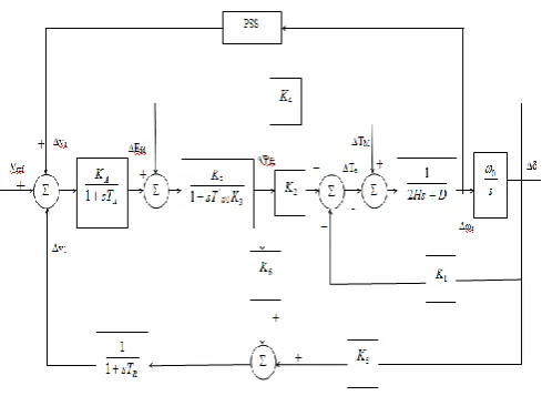
Figure 2.2 Linearized model of SMIB system
The interaction between the speed and voltage control equations of the machine is expressed in terms of six
constants K1-K6. These constants with the exception of K3,
which is only a function of the ratio of impedance, are dependent upon the actual real and reactive power loading as well as the excitation levels in the machine. Investigation of single machine infinite bus model
considering non-linearity like Generator Rate
Constraints (GRC) is also presented.
2.1.1 Generator Rate Constraint (GRC):
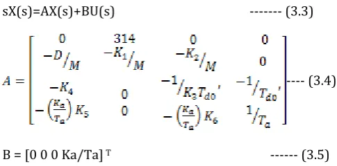
One of the important constraints of the power system is Generator Rate Constraints (GRC) shown in figure 2.3, i.e., the practical limit on the rate of change in the generating power. The GRC would influence the dynamic responses of the system significantly and lead to larger overshoot and longer settling time. In order to take effect of the GRC into account, the linear model of a SMIB will be nonlinear model with saturation limits are the dynamic stability of power system, linearized incremental modes are usually employed. Therefore, the state equation of an inter-connected power system with n synchronous generators can be written in the vector- constant matrices. If each synchronous generator can be modeled by four state variables taking the Laplace transformation of the above equation (2.18) and (2.19). We have the state equation in frequency domain
sX(s)=AX(s)+BU(s) --- (3.3)
---- (3.4)
B = [0 0 0 Ka/Ta] T --- (3.5)
© 2015, IRJET.NET- All Rights Reserved
Page 2330
The control vector can be expressed in the formU(s) = [U1(s) U2(s)…..Un(s)] T --- (3.6)
Ui(s)=Hi(s)Yi(s) --- (3.7)
Yi(s) is the output of generator I and also the input signal to the PSS in generator i.e., three types of input signals Yi are usually employed, namely, speed, power and frequency.
Block diagram:
Figure 3.1: SMIB with power system stabilizer
The transfer function of the PSS Hi(s) is usually of lead lag type.
--- (3.8)
Figure 3.1 shows simple SMIB with power system stabilizer .shaft speed are taken as input to the power system stabilizer so the PSS is also called as delta-omega PSS. For a given operating point, the power system is linearized around the operating point; the Eigen values of the closed-loop system are computed. The typical PSS consists of a wash out function phase compensator and a gain. It is well known that the performance of the PSS is mostly affected by the phase compensator and the gain.
IV. Application of Power System Stabilizers to
the SMIB System
4.1 Conventional Power System Stabilizers:
Controller Design:
Damping torque is produced to overcome rotor oscillation. The action of a PSS is to extend the angular stability limits of a power system by providing supplemental damping to the oscillation of synchronous machine rotors through the generator excitation [29]
Controller is designed to compensate lag between exciter input and electrical torque. The amount of damping introduced depends on the gain of PSS transfer function at that particular frequency of oscillation.
Block diagram:
Figure: 4.1 lead-lag Power System Stabilizer
The transfer function of conventional power system stabilizer is given by
--- (4.1)
© 2015, IRJET.NET- All Rights Reserved
Page 2331
BlockDiagram:Figure 4.2 SMIB with conventional power system
stabilizer
The conventional lead-lag type fixed parameter single input Conventional Power System Stabilizer (CPSS) is widely been used by power system utilities. Due to the changes in operating point, such as heavy load change or system topology change following a major disturbance, this type of PSS offers some problems
From this perspective, the conventional single-input
PSS (machine shaft speed, ωr as single input to PSS)
design approach based on a Single-Machine Infinite Bus (SMIB) linearized model in the normal operating condition has some deficiencies.
However, because a CPSS is designed for a particular operating point for which the linearized transfer function model is obtained, it often does not provide satisfactory results over a wide range of operating conditions.
4.2 Generic Power System Stabilizer:
The generic Power System Stabilizer (GPSS) block is used in the model to add damping to the rotor oscillations of the synchronous machine by controlling its excitation current. Any disturbances that occur in power systems can result in inducing electromechanical oscillations of the electrical generators. Such oscillating swings must be effectively damped to maintain the system stability and reduce the risk of outage. The output signal of the PSS is used as an additional input
(Vstab) to the excitation system block. The PSS input signal can be either the machine speed deviation (dω) or its acceleration power Pa = Pm – Pe (difference between the mechanical power and the electrical power). Figure 4.3 shows Generic Power System Stabilizer.
Figure 4.3 Generic power system stabilizer
To ensure a robust damping, a moderate phase advance has to be provided by the PSS at the frequencies of interest in order to compensate for the inherent lag between the field excitation and the electrical torque induced by the PSS action. The model consists of a low - pass filter, a general gain, a washout high - pass filter, a phase - compensation system and an output limiter. The general gain (K) determines the amount of damping produced by the stabilizer. The washout high -pass filter eliminates low frequencies that are present in the dω signal and allows the PSS to respond only to speed changes. The phase - compensation system is represented by a cascade of the two first - order lead - lag transfer functions used to compensate the phase lag between the excitation voltage and the electrical torque of the synchronous machine.
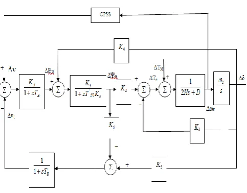
© 2015, IRJET.NET- All Rights Reserved
Page 2332
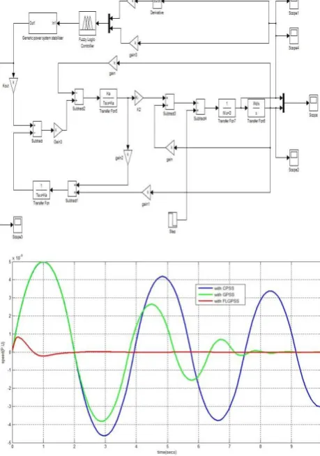
Figure 4.4 SMIB with Generic Power System Stabilizer4.3 Generic Power System Stabilizer with Fuzzy
Logic Controller:
The low frequency oscillation problem deals with using Conventional Power System Stabilizer. These PSS provide the supplementary damping signal to suppress the oscillations and increase the overall stability of the system. But these Conventional PSS use transfer functions of highly linearized models around a particular operating point. So, these systems are unable to provide satisfactory operations over wide range of operating conditions. To overcome this problem, Artificial Intelligence based approaches has been developed. This includes Fuzzy Logic, in which Fuzzy Logic based controller shows great potential to damp out local mode oscillations especially when made adaptive.
Fuzzy Logic is based on data sets which have non-crisp boundaries. The membership functions map each element of the Fuzzy set to a membership grade. Also Fuzzy sets are characterized by several linguistic variables. Each linguistic variable has its unique membership function which maps the date accordingly. Fuzzy rules are also provided along with to decide the output of the Fuzzy logic based system. A problem associated with this is the parameters associated with the membership function and the fuzzy rule, which
broadly depends upon the experience and expertise of the designer. The block diagram of Generic Power System Stabilizer with Fuzzy Logic Controller is as shown in the Figure 4.5.
Figure 4.5 Generic Power System Stabilizer Logic Controller
V. RESULTS AND DISCUSSIONS
© 2015, IRJET.NET- All Rights Reserved
Page 2333
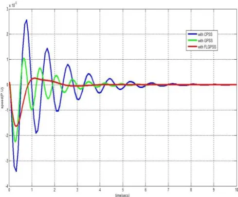
Figure 5.2 Speed when system with GRC Operating at P =1.0, Q = 0, x = 0.4 with CPSS,With GPSS and with FLGPSS
Figure 5.3 Speed when system Operating at P = 1.0,Q =
-0.5, x = 0.4With CPSS, with GPSS, with FLGPSS
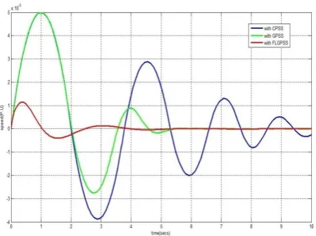
Figure 5.4 Speed when system with GRC Operating at P
= 1.0, Q = -0.5, x = 0.4 with CPSS,With GPSS and with
FLGPSS
Figure 5.5 Speed when system Operating at P = 1.0, Q = 0.5, x = 0.4 With CPSS, with GPSS, with FLGPSS.
Figure 5.6 Speed when system with GRC Operating at P = 1.0, Q = 0.5, x = 0.4 with CPSS,With GPSS and with
© 2015, IRJET.NET- All Rights Reserved
Page 2334
Figure 5.7 Speed when system Operating at P = 0.5, Q= 0,x = 0.4 With CPSS, with GPSS, with FLGPSS
Figure 5.8 Speed when system with GRC Operating at P = 0.5, Q = 0, x = 0.4 with CPSS,With GPSS and with FLGPSS
VI.CONCLUSION
Power System Stabilizers have been thought to improve power system damping by generator voltage regulation depending on system dynamic response. The PSS is a supplementary control system which is often applied as a part of excitation control system The final values of gain (K) and lead time constant (T) obtained are given to Simulink block and the dynamic response curves for the variables ∆ω, ∆ , ∆Vt are taken from the Simulink. The system response curves of the conventional PSS, generic PSS and fuzzy logic generic PSS are compared.
Performance of fixed gain CPSS is better for particular operating conditions. It may not yield satisfactory results when there is a drastic change in the operating point. In this project work, generic PSS and generic PSS with fuzzy logic controller have been systematically assessed to pin-point the main differences in their behaviour that can be ascribed to their intrinsic design characteristics.
SYSTEM DATA:
The system data is as follows:
Machine (P.U) 24kV, 4x55 MVA
Transmission line ckt1 (pu) = Xe1 = j0.4 Transmission line ckt2 (pu) = Xe2 = j0.93
Exciter: power flowincorporating static voltage stability based on
multi-objective adaptiveimmune algorithm, Energy
Conversion and Management, Vol. 49,(2008) 1175-1181.
[2] F. P. Dmello and C. Concordia, “Concepts of synchronous machinestability as affected by excitation
control,” IEEE Trans. Power App.Syst., vol. PAS-88, pp.
316–329, 1969.
[3] E. Larsen and D. Swann, “Applying power system
stabilizers, parts I, IIand III,” IEEE Trans. Power App.
Syst., vol. PAS-100, pp. 3017–3046,Jun. 1981
[4] Ali Feliachi, Xiaofan Zhang, Craig S.Sims,
“PowerSystem stabilizers design using optimal
reducedorder models part I and part II,” IEEE transactionson Power system, vol.3, No.4, Nov 1988.
[5] S. Abe and A. Doi, “A new power system stabilizer synthesis in multimachine power systems,” IEEE Trans. Power App. Syst., vol. PAS–102, pp. 3910–3918, 1983.
[6] A Power System Stabilizer Using Speed and ElectricalPower Inputs - Design and Field Experience, D.C. Lee,R.E. Beaulieu, J.R.R. Service, IEEE Trans. Vol. PAS100,Sept 1981, pp 4151-4157.
© 2015, IRJET.NET- All Rights Reserved
Page 2335
of overall system stability,” IEEE transaction on Powersystem, vol.4, No.2, May 1989.
[8] V. Mukherjee, and S. P. Ghoshal, “Particle swarm optimization-genetic algorithm based fuzzy logic controller for dual input power system stabilizers,” J. Inst. Eng. India, pt. EL, vol. 88, pp. 36-43, Mar. 2008.
[9] C. M. Lim and S.Elangovan, “Design of stabilizers in multimachine power systems,” Proc. Inst. Elect. Eng. C, vol. 132, pp. 146–153, 1985.
[10] C. L. Chen and Y. Y. Hsu, “Coordinated synthesis of multimachine power system stabilizer using an efficient decentralized modal control algorithm,” IEEE Trans. Power Syst., vol. PS–2, pp. 543–551, 1987.
[11] Y. N. Yu and Q. Li, “Pole-placement power system stabilizers design of an unstable nine-machine system,” IEEE Trans. Power Syst., vol. 5, pp.353–358, 1990