R E S E A R C H
Open Access
On the performance of the Code Division
Duplex system using interference rejection
codes
Yufang Yin
1, Gangjun Li
1, Li Li
2and Hua Wei
2*Abstract
In this paper, we investigate the performance of the Code Division Duplex (CDD) system using the interference rejection codes, which exhibit zero correlation values on the relative delay-induced code offsets and can be applied to mitigate the mutual interference between the uplink and downlink. Specifically, we propose to employ loosely synchronous codes to effectively combat the interference through the interference-free window. Moreover, the simplified RAKE structure is proposed as the receiver of the CDD device, which can significantly reduce the complexity in the implementation. The simulation results demonstrate that our proposed method can achieve a near
inference-free performance when the user load of the system is moderate.
1 Introduction
A duplex communication system [1] is a point-to-point system composed of two connected parties or devices that can communicate with one another in both directions, normally termed as uplink and downlink individually. To circumvent the mutual interference between the uplink and downlink, the Frequency Division Duplex (FDD) [1] and Time Division Duplex (TDD) [1] apparatuses are commonly deployed in communication systems. In the FDD system, the uplink and downlink signals are gapped in different frequency bands, while in the TDD system, the uplink and downlink transmissions are identified in differ-ent time slots. In this way, the uplink and downlink can be treated as being orthogonal in the FDD or TDD apparatus since they utilize different frequency or time resources.
Recently, No Division Duplex (NDD) [2, 3] techniques have captured growing interests for the 5G communi-cation system, since they can significantly increase the capacity of the cellular system as well as simplify the infrastructure of the cellular network. The basic philos-ophy of the No Division Duplex [2, 3] is that a radio device can transmit and receive on the same frequency at the same time; more explicitly, it can operate in a full-duplex fashion. However, as the radio signals attenuate
*Correspondence: [email protected]
2Chengdu University of Information and Technology, Chengdu, China Full list of author information is available at the end of the article
quickly in an exponential way over the distance, the signal from a local transmitting antenna is hundreds of thou-sands of times stronger than transmissions from other nodes. Therefore, the challenge in implementing a full-duplex system is to recover the desired signal from the excessively strong local interferers. Hence, a complicated interference canceller [3] must be deployed in the NDD device to combat the local interference, in both the analog RF component as well as the digital baseband component. In Code Division Multiple Access (CDMA) systems, the spreading sequences characterize the properties of the associated Intersymbol Interference (ISI) as well as the Multiple Access Interference (MAI) [4]. Traditional spreading sequences, such asm-sequences [4], Gold codes [4], and Kasami codes [4], exhibit non-zero off-peak auto-correlations and cross-auto-correlations, which result in a high MAI in the system. To circumvent this issue, the ideal solution is to design the optimal sequences whose auto-and cross-correlations are zero for the infinite code off-sets, as shown in Fig. 1a. However, this kind of perfect sequence does not exist in theory. Therefore, considerable research has been invested on the interference rejection code which can exhibit zero correlation values on the rel-ative delay-induced code offsets. The area which has the value of zero correlation is the so-called Zero Correlation Zone (ZCZ) or Interference-Free Window (IFW) of the spreading code [5], as shown in Fig. 1d. The auto- and
Fig. 1Cross-correlations of four different codes.aPerfect sequence.bWalsh code.cGold code.dInterference rejection code (LS code)
cross-correlation properties of four spreading codes are exhibited in Fig. 1. In this figure, we can observe that the correlation value of the interference rejection code is zero in IFW. Loosely Synchronous (LS) code [6, 7] is one of these specific interference rejection codes which exhibit an IFW, where the off-peak values of aperiodic auto- and cross-correlations are zero, resulting in zero ISI and zero MAI in the IFW. Given these conditions, a major ben-efit of the interference rejection codes is that they are capable of combating the mutual interference between the uplink and downlink without a complicated interfer-ence canceller. Hanzo, Wei, and Ni [8–10] investigated the performance of the CDMA system in the context of the deployment the LS codes. However, in their work, the power control [11] scheme is employed to avoid the near-far effect, and only the cellar communication scenarios are evaluated in previous work. In [9, 12], the interference rejection codes are deployed in the multi-carrier CDMA system and the performance is analyzed. The authors in [13] investigated the performance of the CDMA system in conjunction with the multiple antenna technique and the interference rejection code. Various chip waveforms [14] are investigated for the LS codes, and the network capacity in the cellular scenario is analyzed in [15].
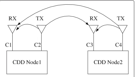
In this paper, to circumvent the implementation of complicated interference canceller, Code Division Duplex (CDD) is proposed for a synchronous communication system. As shown in Fig. 2, the basic concept of the CDD is that the downlink and uplink signals are dis-tinguished by their unique spread sequence Ci, i.e., the CDD radio can transmit and receive simultaneously at the same frequency band with different spreading sig-natures. The state of the art CDD device can operate in the same fashion as the NDD device. However, the advantage of the CDD receiver is to employ a simple matched filter or RAKE receiver rather than a complicated
interference canceller in the NDD device owing to the cross-correlation properties of the interference rejection code, which is beneficial in the engineering implementa-tion and power saving.
In this paper, we will investigate the performance of CDD communication systems in the context of two prac-tical scenarios. The first scenario is a cellular-like commu-nication system, where a base station node operates as the centric node and all the other CDD nodes must commu-nicate with the center node. In this specific scenario, the center node has a much stronger transmission power than other nodes. The second scenario is an ad hoc commu-nication system where each CDD device transmits on the same power in the network and can communicate with each other. In this contribution, we will investigate the Bit Error Rate (BER) performance and capacity of CDD systems in both scenarios when communicating over a Nakagami-mchannel.
This paper is organized as follows. In Section 2, we will introduce the specific interference rejection code, namely LS code, while in Section 3, we will describe the model
of the CDD system and fading channel. In Section 4, we will characterize the BER performance of the CDD com-munication, and in Section 5, we will discuss our findings. Finally, in Section 6, we will offer our conclusion.
2 Interference rejection codes
There exists a specific family of spreading codes, which exhibit an IFW; more specifically, Loosely Synchronized (LS) codes [6] exploit the properties of the so-called orthogonal complementary sets [6, 7]. Since the detailed construction method of binary LS codes was described in [6, 9, 10], here, we only focus our attention on the properties and the applications of the LS codes [16, 17].
Generally, an LS code can be denoted as LS(N,P,W0), which denotes the family of LS codes generated by apply-ing a (P×P)-dimensional Walsh-Hadamard (WH) matrix to an orthogonal complementary code set of length N and insertingW0number of zeros between two orthog-onal complementary sets [6, 9, 10]. The constructed LS(N,P,W0)codes can be constructed for any arbitrary length of the codes by selecting the proper parameterN, and then, the generated LS codes can exhibit an IFW of interference rejection code as shown in Fig. 1; more explicitly, the spreading signature function ci(t),cj(t) of the constructed LS codes satisfy:
−∞
−∞ ci(t)cj(t−τ)dt=0, τ <WI, i=j (1) whereci(t)andcj(t)are the signature functions in the gen-erated LS(N,P,W0)code set andWI is the width of the IFW. More explicitly, the constructed LS(N,P,W0)codes are still orthogonal to each other even in the scenarios of the multipath environment provided that the delay spread of the multipath is less than the width of IFW. Hence, the LS code with inherent IFW can effectively suppress the Multipath Interference (MPI) and multiuser access inter-ference (MAI), which also significantly simplify the design of receiver as well as reduce the complexity of the receiver in CDMA system.
For example, the LS(N,P,W0) codes can be gen-erated based on the complementary pair of [6, 16], and the total number of available codes in the fam-ily of LS(N,P,W0) is given by NP. The total
num-ber of NP codes can be classified by N sets of P
number of LS codes through their Walsh-Hadamard
Matrix, and each set has P number of LS codes. The
LS codes in the same set exhibit an IFW length of [−WI,+WI], where we have WI = min{W0,N − 1}. The aperiodic auto-correlation and cross-correlation functionρkk(τ),ρjk(τ)of the codes belonging to the same set will be zero, provided that we haveτ ≤ WITc. Fur-thermore, the LS codes belonging to theN different sets are still orthogonal to each other at zero offset, namely in a perfectly synchronous environment. However, the LS
codes belonging to the N different sets will lose their orthogonality, when they have a non-zero code offset.
To combat the interference incurred by its own trans-mission, the spreading codes in the CDD device have the following assignment policy: the spreading codes of the uplink and downlink are wisely chosen to belong to different sets of Walsh-Hadamard. The benefit of this assignment is that the spreading codes between the uplink and downlink have the maximum width of the IFW, which can guarantee the orthogonality between the uplink and downlink in one CDD node so that their mutual interfer-ence can be negligible.
3 System model
3.1 System model
Assume that the system supports K synchronous users and each user is assigned two unique spreading signature waveforms for its uplink and downlink, respectively. The spreading signature waveform can be noted as ck(t) = G−1
i=0
ckiψTc(t −iTc), whereG is the spreading gain and
ψTc(t)is the rectangular chip waveform, which is defined over the interval [ 0,Tc). Consequently, when theKusers’ signals are transmitted over the frequency-selective fading channel, the complex low-pass equivalent signal received at a given RX antenna can be expressed as:
R(t) = where N(t) is the complex-valued low-pass-equivalent AWGN (additive white Gaussian noise) having a double-sided spectral density ofN0andτkis the propagation delay between the transmitter and receiver for user k. In the same CDD device, τk is assumed to be 0, while in dif-ferent CDD devices,τk is determined by the propagation distance: without loss of generality,τk = dkc, wherecis the speed of light. Lp is the total number of resolvable paths.Pk is the received power, which is determined by the large-scale fading of the wireless channel.
3.2 Wireless large-scale fading model
resorting to complicated path loss models, which is suffi-ciently accurate to approximate the real channel model. In this contribution, the following simplified models [1] for path loss as a function of distance are commonly used for system design:
Pr=PtGa
d d0
−γ
, (3)
where d0 is the wavelength of the radio signal,d is the distance between the transmitter and receiver, andGais the constant which is related to the characteristic of the antenna, such as the height and direction. Parameterγ is the exponential attenuation factor which is related to the practical environment. Generally, the attenuation factorγ is about 2 to 4 according to the free-space, indoor, urban, or hilly environments.
3.3 Channel model
The DS-CDMA signal experiences independent
frequency-selective Nakagami-m fading. The complex low-pass equivalent representation of the Channel Impulse Response (CIR) encountered by thekth user is given by [19]:
hk(t)= Lp−1
l=0
hklδ(t−lTc)exp
jθkl , (4)
where hkl represents the Nakagami-distributed fading envelope,lTcis the relative delay of thelth path of userk with respect to the main path, whileLpis the total num-ber of resolvable multipath components. Furthermore,θkl is the uniformly distributed phase-shift of thelth multi-path component of the channel andδ(t)is the Kronecker delta function. More explicitly, theLP multipath attenu-ations {hkl} are independent Nakagami-distributed ran-dom variables with a Probability Density Function (PDF) of [20–22]:
p(hkl) = M(hkl,mkl,kl), M(R,m,) = 2m
mR2m−1
(m)m e
(−m/)R2, (5)
where (·) is the gamma function [19] and mkl is the Nakagami-m fading parameter, which characterizes the severity of the fading for thelth resolvable path of user k[23] . Specifically,mkl = 1 represents Rayleigh fading, mkl → ∞corresponds to the conventional Gaussian sce-nario, and mkl = 1/2 describes the so-called one-sided Gaussian fading, i.e., the worst-case fading condition. The Rician and log-normal distributions can also be closely approximated by the Nakagami distribution in conjunc-tion with values ofmkl > 1. The parameterkl in Eq. 5 is the second moment ofhkl, i.e., we havekl=E[(hkl)2]. We assume a negative exponentially decaying Multipath Intensity Profile (MIP) given bykl=k0e−ηl, η≥0,l=
0,. . .,Lp−1, wherek0is the average signal strength cor-responding to the first resolvable path andηis the rate of average power decay.
4 BER performance analysis
As shown in Fig. 3, let the first user be the user of inter-est and consider a receiver using de-spreading as well as multipath diversity combining. The conventional matched filter-based RAKE receiver using maximum ration com-bining (MRC) can be invoked for detection, where we assume that the RAKE receiver combines a total of Lr number of diversity paths, which may be more or possi-bly less than the actual number of resolvable components at the current chip rate. It is advocated that the system has achieved perfect time synchronization and perfect estimates of the channel tap weights. Then, after appropri-ately delaying the outputs of the individual matched filter, in order to coherently combine theLrnumber of path sig-nals with the aid of the RAKE receiver, the outputZkl of the RAKE receiver’slth finger sampled att=T+lTc+τk can be expressed as:
Zkl =Dkl+Ikl, (6)
whereDklrepresents the desired direct component, which can be expressed as:
Dkl =
√
2PTsbk[0]h2kl, (7)
whereTSis the symbol duration.
The MRC’s decision variableZk, which is given by the sum of all the RAKE fingers’ outputs, can be expressed as:
Zk= Lr−1
l=0
Zkl. (8)
The RAKE fingers’ output signalZkl is a Gaussian dis-tributed random variable with a mean ofDkl.
The term Ikl in Eq. 6 represents the total interference incurred by the Multipath Interference (MPI) as well as the Multiple Access Interference (MAI), which can be expressed as:
Ikl =Ikl[S]+Ikl[M]+Nk, (9) whereIkl[S] represents the multipath interference imposed by the user of interest, which can be expressed as:
Ikl[S]=
Furthermore,Ikl[M] represents the multiuser interfer-ence inflicted by theK−1 number of interfering signals, which can be expressed as:
Ikl[M] = the phase differences between the incoming carrier and the locally generated carrier used in the demodulation. Finally, the noise term in Eq. 9 can be expressed as:
Nkl=hkl Ts
0
n(t)c[t] cos(2πfct+θkl)dt, (12) which is a Gaussian random variable with a zero mean and a variance ofN0Tsh2kl, where{hkl}represents the path attenuations.
Furthermore,Ikl[S] represents the MPI imposed by the user of interest. Without loss of generality, we can assume that the width of the IFW is longer than the channel spread timeLpTc, and in this case, the MPI becomes zero since the auto-correlation of the spreading code is zero.
Hence, the performance of the CDD system is mainly determined by the MAI termIkl[M], which is affected by channel delay profile, distance amongst the nodes, and the number of users supported in a cell.
Again, the uplink TX and downlink RX have different spreading sequences for thekth user in one CDD device, and recall that the system can assign different sets of the spreading codes for the uplink and downlink; more specif-ically, the spreading codes of the uplink and downlink have the maximum width of IFW in the generated LS codes. And the distance between the TX antenna and RX antenna is very close, i.e.,τk=0. Hence, after the matched filter and RAKE receiver, the interference introduced by its own transmission can be ignored due to the inherent orthogonality of the spreading codes. Thus, the MAI are mainly introduced by other CDD device nodes.
Since the power control is difficult to be implemented in the CDD system, the near-far effect must be taken into account for the BER performance analysis. Assume that the power of the interested signals isPk while the power
of the interference isPj, and Pk andPj can be obtained from Eq. 3.
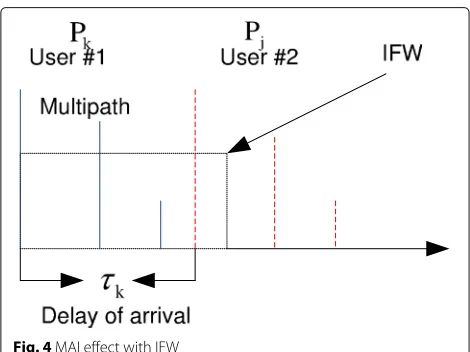
As shown in Fig. 4, if one path of the channel impulse response of the interference user is located within the IFW, this specific path will not introduce any interfer-ence to the interested signals. More explicitly, only these paths which are located outside the interference-free win-dow will introduce the MAI to the desired signal. Without loss of generality, we can assume that the multipath inten-sity profile of all users obeys the same distribution, i.e.,
k0 = 0,k = 1, 2, ...K, andEb = PTs is the energy per bit. Thus, the variance of thelth RAKE finger’s out-put samplesZklfor a given set of channel amplitudes{hkl} may be approximated as [23, 24]:
σ2 agation delay of the interference userjand the interested userk, respectively;Lp is the total number of resolvable paths; andu(x)is the step function, i.e.,u(x) = 1,x ≥0, otherwise u(x) = 0,x < 0. According to the large-scale fading model, Pj and Pk are the strength of the received signals, which can be derived in Eq. 3 as Pj = PtjGa
Hence, the MRC’s output sample Zk can be approxi-mated by a Gaussian random variable with a mean of
E [Zk]=
Hence, the BER using BPSK modulation conditioned on a set of fading attenuations{hkl,l = 0, 1,. . .,Lr−1}can be expressed as [1, 18]:
Pb(γ )=Q
whereQ(x)represents the GaussianQ-function which can also be simplified as [1, 23]:
Q(x)= 1 Furthermore, 2γlin Eq. 17 represents the output Signal to Interference plus Noise Ratio (SINR) at thelth finger of the RAKE receiver.
Let us now substitute Eqs. 13, 15, and 16 into Eq. 17, and the expressions under the square-root functions must be equal, which allows us to expressγlas follows:
γl=
For the convenience of the BER derivation, we define a termγcas:
the Nakagami-mdistribution characterized by Eq. 5, and the PDF ofγlcan be formulated as: the conditional BER expression of Eqs. 17 and 21 over the joint PDF of the instantaneous SNR values.
5 Simulation performance of CDD
As we mentioned before, two scenarios are investigated in this paper. The first scenario is a cellular system which has a center node, and all other nodes besides the center node only communicate with the center one. The second sce-nario is a relay and ad hoc communication environment,
where any two of the nodes can communicate with each other. For the CDD performance evaluation, we assume that the system has a chip rate of 1.2288 M chips which is the same as the CDMA2000 and EVDO systems [25]. The bandwidth of our system is 1.25 MHz. The carrier fre-quency of the system isfc = 2 GHz, and the large-scale fading factorγ = 2.5. Moreover, the radius of a cell is configured to 2000 m. All the CDD nodes are operated in synchronous transmission mode, i.e., all nodes transmit simultaneously. We also assume that the maximum delay spread of the channel isτ = 3μs [11]. Thus, the number of resolvable paths is considered asLp = Tcτ +1 = 4, where τ = 3μs, and the channel’s delay spread profile is negatively exponentially distributed with the factor η in the range of [0.3, 3] μs. The RAKE receiver combines Lr =3 number of fingers for BER performance evaluation, and the channel’s exponential decay factor isη=0.2.
In our simulation, the LS(4,32,4) codes are deployed as the spreading codes. More explicitly, the total length of the LS(4,32,4) code isL = NP+2W0 = 136 chips, and its spreading factor may be calculated by simply noting that each bit to be transmitted is spread by one of the con-stituent LS(4,32,4) codes. Although the length of this LS code isL=NP+2W0=136, the effective spreading gain of the LS code is identical toGeff = 128 since the insert-ing zeros must not be taken into account. The LS(4,32,4) codes are constituted by a total of 128 spreading codes. The width of the IFWWI and the number of supported userKsatisfies that:
WI = 4,K ≤16; WI = 2, 16<K≤32; WI = 1, 32<K≤64; WI = 0, 64<K≤128.
0 100 200 300 400 500 600 700 800 900 1000 10−4
10−3 10−2 10−1
G=128, SNR=20dB, K=2, η=0.2,m=1, L
r=3 Lp=4,
BER
Distance to Interfernce Node[m]
W
I
=0
W
I
=1
W
I
=2
W
I
=3
W
I
=4
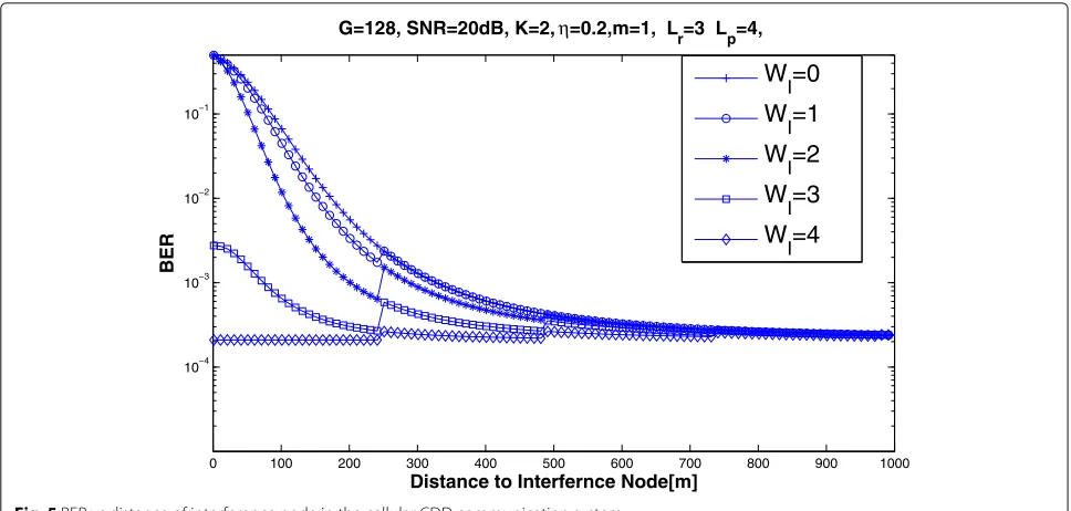
Fig. 5BER vs distance of interference node in the cellular CDD communication system
or 4, the interference is suppressed significantly and the effect of the interference node is negligible.
The performance of CDD in two common scenarios is shown in Fig. 6. In the cellular scenario, a center node or Base Station (BS) exists in the network, which has a high transmission power than other nodes. In our simu-lation, we assume that the base station node has a 20-dB higher transmission power. The second is an ad hoc sce-nario where each node has the same transmission power. Figure 6 plots the BER performance of the CDD com-munication system in the context of a various number of usersK. In Fig. 6, we can observe that the performance
in the ad hoc scenario is superior than that in the cellular scenario. This phenomenon is reasonable since the cel-lular environment exists as a strong base station which also acts as a strong interference node to other destina-tion nodes and then degrades the BER performance in the cellular condition.
Figures 7 and 8 exhibit the performance of the CDD system in conjunction with various supported users K. From Fig. 7, we can observe that the near interference-free performance can be achieved when the number of users K is less than 16 since the spreading codes have the maximum width of the IFW in this condition. As
0 5 10 15 20 25 30
10−5 10−4 10−3 10−2 10−1
G=128,η=0.2, m=1, L r=3 Lp=4,
BER
E b/N0[dB]
Analytical result Ad−hoc Scenario K=16 Analytical result Ad−hoc Scenario K=32 Analytical result Celluar Scenario K=16 Analytical result Celluar Scenario K=32 Simulation result Ad−hoc Scenario K=16 Simulation result Ad−hoc Scenario K=32 Simulation result Celluar Scenario K=16 Simulation result Celluar Scenario K=32
0 5 10 15 20 25 30 10−4
10−3 10−2 10−1
G=128,η=0.2, m=1, L
r=3 Lp=4,
BER
Eb/N0[dB]
K=16
K=32
K=64
Fig. 7BER performance of the CDD communication system with various number of usersK
the number of users is increased to 32, the performance of the CDD system is degraded moderately, since the width of the IFW is still maintained in WI ≤ 2. How-ever, when the number of users is increased to more than 64, the performance is degraded significantly since the width of IFW is decreased to 0 ∼ 1, which reduces the capability of combating the MAI. Figure 8 portrays the
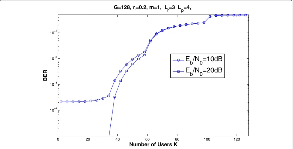
BER performance of the CDD in conjunction with vari-ous usersK. Two different SNR parameters are configured in our simulation, i.e., SNR = 10 dB and SNR = 20 dB, respectively. From Fig. 8, we can conclude that the CDD system exhibits a near interference-free performance in the case K ≤ 32. In Figs. 7 and 8, it is advocated that the CDD system should be deployed in a relatively-low
0 20 40 60 80 100 120
10−4 10−3 10−2 10−1
G=128,η=0.2, m=1, L
r=3 Lp=4,
BER
Number of Users K
E
b
/N
0=10dB
E
b
/N
0=20dB
load of users. For a spreading gain of 128 systems, the
CDD system can supportK = 40 user communications
simultaneously without the mutual interference; this load is promising since the linear Minimum Mean Square Esti-mator (MMSE) multiuser detector with a much higher complexity can only support to K = 40 to achieve an ideal performance. Similarly, the performance of the linear MMSE multiuser detector [26, 27], the Parallel Inter-ference Canceller (PIC) [26, 27], and Serial InterInter-ference Canceller (SIC) [26, 27] deteriorates significantly for the high load scenario in a CDMA system; furthermore, the traditional MMSE detector, PIC, and SIC suffer the seri-ous near-far effect and degrade the performance in our CDD scenarios. The ideal Maximum Likelihood detector [26, 27] can solve this issue; however, the complexity of the ML detector is excessively high so that it is impossible to implement in practical communication systems.
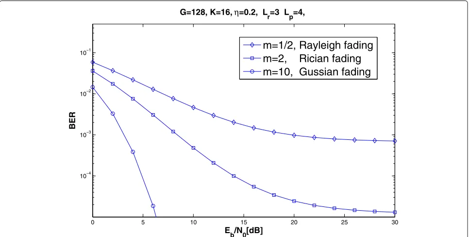
Finally, Fig. 9 plots the BER performance of different channel fading models. The Nakagami-m channel is a generic model for the wireless channel, where the choice of the parameter m determines the fading type of the channel model. In Fig. 9, three different fading models are simulated and analyzed in our investigation. More explic-itly, the Rayleigh fading [1, 18], Rician fading [1, 18], and Gaussian Fading [1, 18] are evaluated in the simulation. In the practical applications in a cellular communication, the Rayleigh fading and Rician fading model are com-monly adopted for the performance evaluation. Hence, in this detection, we evaluate the CDD performance in
conjunction with the real scenario of the cellar commu-nications. The simulation results in Fig. 9 conform to the mathematic analysis, and we can conclude that the perfor-mance of Rayleigh fading is the worst and the perforperfor-mance of Gaussian fading is the best amongst these three fading models.
6 Conclusions
In this paper, we investigated the BER performance of the CDD communication system, which can exhibit the same operation fashion as the NDD device. Moreover, the advantage of the CDD is that the receiver can be simplified as the matched filter or RAKE receiver by carefully select-ing our proposed interference rejection codes—LS codes. Hence, our proposed method can significantly reduce the complexity and difficulty in the implementation of the NDD fashion. Our simulation results show that the CDD system can achieve a near interference-free performance in a low-user load scenario due to the limited number of available LS codes having a certain IFW width; more explicitly, our simulation and analysis show that the CDD system can achieve an ideal performance when the num-ber of user K ≤ 32, and in this condition, a simple matched filter or RAKE receiver is sufficient to combat all the interference. For future research, the method of the smart assignment of the spreading codes will be investi-gated to reduce interference between neighboring nodes and increase the capacity and spectrum efficiency of the CDD network.
0 5 10 15 20 25 30
10−4 10−3 10−2 10−1
G=128, K=16, η=0.2, L
r=3 Lp=4,
BER
E
b/N0[dB]
m=1/2, Rayleigh fading
m=2, Rician fading
m=10, Gussian fading
Acknowledgements
This work is supported by the Scientific Research Foundation of Chengdu Technological University (grant no. 2017RC004) and the Scientific Research Foundation of CUIT (KYTZ201501, KYTZ201502); the Sichuan Provincial Department of Science and Technology in granted program nos. 2015GZ0340, 2015GZ0286, 2015GZ0290, and 2015RZ0060; and the National Defense Innovation Technology Program 173-162-11-ZT-003-012-02. Finally, great thanks to the anonymous reviewers for the their valuable suggestions to improve the quality of this paper.
Funding
The work is sponsored by Chengdu Technological University (grant no. 2017RC004); Chengdu University of Information and Technology (KYTZ201501, KYTZ201502); Sichuan Provincial Department of Science and Technology in granted program nos. 2015GZ0340, 2015GZ0286, 2015GZ0290, and 2015RZ0060; and the National Defense Innovation Technology Program 173-162-11-ZT-003-012-02.
Authors’ contributions
YY and HW contributed to the conception and design of the study. YY, LL, GL, and HW contributed to the acquisition of data and simulation. YY, GL, LL, and HW contributed to the analysis and interpretation of the simulation data. All authors read and approved the final manuscript.
Authors’ information
Dr. Yufang Yin obtained her Ph.D. degree in 2007 from the EE department, the University of Texas at San Antonio. From January 2009 to June. 2012, she worked as the specialist and research scientist in Nokia Networks. From July 2012 to October 2014, she worked as the staff engineer in Spread Spectrum Communication. Since November 2016, she joined Chengdu Technological University. Her research area includes statistical signal processing and applied machine learning.
Gangjun Li received the B.S. degree in Mechanical Engineering from the University of Electronic Science and Technology of China in 1987 and the M.S. degree in Mechanics from the Harbin Institute of Technology in 1990. He received the Ph.D. degree in Robotics Engineering from the Southwest Jiaotong University in 2002. Since 2010, he is a professor of Chengdu Technological University (CDTU). His research interests are in areas of robotics, simulation, modeling of complex systems, and nonlinear control.
Dr. Li (Alex) Li obtained his Ph.D. degree in electronics engineering from the University of York in 2014, and now he is working in Chengdu University of Information Technology, China. His research interests include fields of wireless communication, MIMO-OFDM, adaptive filtering, and ASIC design.
Hua Wei obtained his Ph.D. degree from the ECS department, University of Southampton in September 2005. From January 2006 to September 2014, he worked as the principle engineer in Spread spectrum Communication for wireless modem design. Since September 2014, he joined in Chengdu University of information Technology. His research area includes adaptive equalization, signal processing, and VLSI design for wireless baseband processor.
Competing interests
The authors declare that they have no competing interests.
Publisher’s Note
Springer Nature remains neutral with regard to jurisdictional claims in published maps and institutional affiliations.
Author details
1Chengdu Technological University, Chengdu, China.2Chengdu University of
Information and Technology, Chengdu, China.
Received: 6 January 2017 Accepted: 24 August 2017
References
1. A GoldSmith,Wireless communications. (Cambridge University Press, 2005) 2. T Riihonen, S Werner, R Wichman, Mitigation of loopback self-interference in full-duplex MIMO relays. IEEE Trans. Sign. Process.59(12), 5983–5993 (2011)
3. M Duarte, C Dick, A Sabharwal, Experiment-driven characterization of full-duplex wireless systems. IEEE Trans. Wirel. Commun.1(12), 4296–4307 (2012) 4. L Hanzo, LL Yang, EL Kuan, K Yen,Single- and multi-carrier DS-CDMA. (John
Wiley and IEEE Press, 2003), p. 1060
5. P Fan, L Hao, Generalized orthogonal sequences and their applications in synchronous CDMA systems. IEICE Trans. Fundam.E83-A, 2054–2069 (2000) 6. S Sta ´nczak, H Boche, M Haardt, inGLOBECOM ’01. Are LAS-codes a
miracle? vol. 1 (IEEE Global Telecommunications Conference, San Antonio, 2001), pp. 589–593
7. CC Tseng, CL Liu, Complementary sets of sequences. IEEE Trans. Inf. Theory.18, 644–652 (1972)
8. H Wei, L Hanzo, On the uplink performance of asynchronous LAS-CDMA. IEEE Trans. Wirel. Commun.5, 1187–1196 (2006)
9. H Wei, L-L Yang, L Hanzo, Interference-free broadband single- and multi-carrier DS-CDMA. IEEE Commun. Mag.43(2), 68–73 (2005) 10. S Ni, H Wei, JS Blogh, L Hanzo, Network performance of asynchronous
UTRA-like FDD/CDMA systems using loosely synchronised spreading codes. IEEE Veh. Technol. Conf.2, 1359–1363 (2003)
11. WCY Lee,Mobile communications engineering, 2nd ed. (McGraw-Hill, New York, 2008)
12. L-L Yang, W Hua, L Hanzo, Multiuser detection assisted time- and frequency-domain spread multicarrier code-division multiple-access. IEEE Trans. Veh. Technol.55(1), 397–404 (2006)
13. H Wei, L-L Yang, L Hanzo, Downlink space–time spreading using interference rejection codes. IEEE Trans. Veh. Technol.55(6), 1838–1847 (2006) 14. H Wei, L Hanzo, in2005 6th IEE International Conference on 3G and Beyond.
LAS-CDMA Using Various Time Domain Chip-Waveforms (IET Conference Publications, 2005)
15. X Liu, H Wei, L Hanzo, Analytical bit error rate performance of DS-CDMA ad hoc networks using large area synchronous spreading sequences. IET Commun.1(4), 760–764 (2007)
16. RL Frank, Polyphase complementary codes. IEEE Trans. Inf. Theory.26, 641–647 (1980)
17. R Sivaswamy, Multiphase complementary codes. IEEE Trans. Inf. Theory. 24, 546–552 (1978)
18. D Tse, P Viswanath,Fundamentals of wireless communication. (Cambridge University Press, 2005)
19. JG Proakis,Digital communications, 3rd edn. (Mc-Graw Hill International Editions, 1995)
20. N Nakagami, inStatistical methods in radio wave propagation, ed. by WG Hoffman. Them-distribution, a general formula for intensity distribution of rapid fading (Pergamon, Oxford, 1960)
21. T Eng, LB Milstein, Coherent DS-CDMA performance in Nakagami multipath fading. IEEE Trans. Commun.43, 1134–1143 (1995) 22. V Aalo, O Ugweje, R Sudhakar, Performance analysis of a DS/CDMA
system with noncoherentM-ary orthogonal modulation in Nakagami fading. IEEE Trans. Veh. Technol.47, 20–29 (1998)
23. M-S Alouini, AJ Goldsmith, A unified approach for calculating error rates of linearly modulated signals over generalized fading channels. IEEE Trans. Commun.47, 1324–1334 (1999)
24. MK Simon, M-S Alouini, A unified approach to the probability of error for noncoherent and differentially coherent modulation over generalized fading channels. IEEE Trans. Commun.46, 1625–1638 (1998)
25. 3GPP2, Overviews of the CDMA2000 standards. Website: www.3gpp2.org 26. X Wang, VH Poor,Wireless communication systems: advanced techniques
for signal reception. (Prentice Hall, 2011)