Volume 2007, Article ID 60654,11pages doi:10.1155/2007/60654
Research Article
Transmit Diversity at the Cell Border Using
Smart Base Stations
Simon Plass, Ronald Raulefs, and Armin Dammann
German Aerospace Center (DLR), Institute of Communications and Navigation, Oberpfaffenhofen, 82234 Wessling, Germany
Received 27 October 2006; Revised 1 June 2007; Accepted 22 October 2007
Recommended by A. Alexiou
We address the problems at the most critical area in a cellular multicarrier code division multiple access (MC-CDMA) network, namely, the cell border. At a mobile terminal the diversity can be increased by using transmit diversity techniques such as cyclic delay diversity (CDD) and space-time coding like Alamouti. We transfer these transmit diversity techniques to a cellular environ-ment. Therefore, the performance is enhanced at the cell border, intercellular interference is avoided, and soft handover procedures are simplified all together. By this, macrodiversity concepts are exchanged by transmit diversity concepts. These concepts also shift parts of the complexity from the mobile terminal to smart base stations.
Copyright © 2007 Simon Plass et al. This is an open access article distributed under the Creative Commons Attribution License, which permits unrestricted use, distribution, and reproduction in any medium, provided the original work is properly cited.
1. INTRODUCTION
The development of future mobile communications systems follows the strategies to support a single ubiquitous radio ac-cess system adaptable to a comprehensive range of mobile communication scenarios. Within the framework of a global research effort on the design of a next generation mobile sys-tem, the European IST project WINNER—Wireless World Initiative New Radio—[1] is also focusing on the identifica-tion, assessment, and comparison of strategies for reducing and handling intercellular interference at the cell border. For achieving high spectral efficiency the goal of future wireless communications systems is a total frequency reuse in each cell. This leads to a very critical area around the cell borders. Since the cell border area is influenced by at least two neighboring base stations (BSs), the desired mobile termi-nal (MT) in this area has to scope with several sigtermi-nals in parallel. On the one hand, the MT can cancel the interfer-ing signals with a high signal processinterfer-ing effort to recover the desired signal [2]. On the other hand, the network can man-age the neighboring BSs to avoid or reduce the negative in-fluence of the transmitted signals at the cell border. Due to the restricted power and processing conditions at the MT, a network-based strategy is preferred.
In the region of overlapping cells, handover procedures exist. Soft handover concepts [3] have shown that the usage of two base stations at the same time increases the robust-ness of the received data and avoids interruption and calling
resources for reinitiating a call. With additional information about the rough position of the MT, the network can avoid fast consecutive handovers that consume many resources, for example, the MT moves in a zigzag manner along the cell border.
Already in the recent third generation mobile commu-nications system, for example, UMTS, macrodiversity tech-niques with two or more base stations are used to provide reliable handover procedures [4]. Future system designs will take into account the advanced transmit diversity techniques that have been developed in the recent years. As the cell sizes decrease further, for example, due to higher carrier frequen-cies, the cellular context gets more dominant as users switch cells more frequently. The ubiquitous approach of having a reliable link everywhere emphasizes the need for a reliable connection at cell border areas.
This can be circumvented by using cyclic delays which results in the cyclic delay diversity (CDD) technique [6].
Space-time block codes (STBCs) from orthogonal de-signs [7] improve the performance in a flat and frequency selective fading channel by coherently adding the signals at the receiver without the need for multiple receive anten-nas. The number of transmit antennas increases the perfor-mance at the expense of a rate loss. The rate loss could be reduced by applying nearly orthogonal STBCs which on the other hand would require a more complex space-time de-coder. Generally, STBCs of orthogonal or nearly orthogonal designs need additional channel estimation, which increases the complexity.
The main approach of this paper is the use and inves-tigation of transmit diversity techniques in a cellular envi-ronment to achieve macrodiversity in the critical cell border area. Therefore, we introduce cellular CDD (C-CDD) which applies the CDD scheme to neighboring BSs. Also the Alam-outi scheme is addressed to two BSs [8] and in the follow-ing this scheme is called cellular Alamouti technique (CAT). The obtained macrodiversity can be utilized for handover de-mands, for example.
Proposals for a next generation mobile communications system design favor a multicarrier transmission, namely, OFDM [9]. It offers simple digital realization due to the fast Fourier transformation (FFT) operation and low complexity receivers. The WINNER project aims at a generalized multi-carrier (GMC) [10] concept which is based on a high flexible packet-oriented data transmission. The resource allocation within a frame is given by time-frequency units, so called chunks. The chunks are preassigned to different classes of data flows and transmission schemes. They are then used in a flexible way to optimize the transmission performance [11].
One proposed transmission scheme within GMC is the multicarrier code division multiple access (MC-CDMA). MC-CDMA combines the benefits of multicarrier transmis-sion and spread spectrum and was simultaneously proposed in 1993 by Fazel and Papke [12] and Yee et al. [13]. In ad-dition to OFDM, spread spectrum, namely, code division multiple access (CDMA), gives high flexibility due to simul-taneous access of users, robustness, and frequency diversity gains [14].
In this paper, the proposed techniques C-CDD and CAT are applied to a cellular environment based on an MC-CDMA transmission scheme. The structure of the paper is as follows.Section 2describes the used cellular multicarrier system based on MC-CDMA.Section 3introduces the cellu-lar transmit diversity technique based on CDD and the ap-plication of the Alamouti scheme to a cellular environment. At the end of this section both techniques are compared and the differences are highlighted. A more detailed analytical in-vestigation regarding the influence of the MT position for the C-CDD is given inSection 4. Finally, the proposed schemes are evaluated inSection 5.
2. CELLULAR MULTICARRIER SYSTEM
In this section, we first give an outline of the used MC-CDMA downlink system. We then describe the settings of the cellular environment and the used channel model.
2.1. MC-CDMA system
The block diagram of a transmitter using MC-CDMA is shown in Figure 1. The information bit streams of the Nu
active users are convolutionally encoded and interleaved by the outer interleaver Πout. With respect to the modulation
alphabet, the bits are mapped to complex-valued data sym-bols. In the subcarrier allocation block,Ndsymbols per user
are arranged for each OFDM symbol. Thekth data symbol is multiplied by a user-specific orthogonal Walsh-Hadamard spreading code which provides chips. The spreading length
Lcorresponds to the maximum number of active usersL= Nu,max. The ratio of the number of active users toNu,max
rep-resents the resource load (RL) of an MC-CDMA system. An inner random subcarrier interleaverΠinallows a
bet-ter exploitation of diversity. The input block of the inbet-ter- inter-leaver is denoted as one OFDM symbol andNsOFDM
sym-bols describe one OFDM frame. By taking into account a whole OFDM frame, a two-dimensional (2D) interleaving in frequency and time direction is possible. Also an inter-leaving over one dimension (1D), the frequency direction, is practicable by using one by one OFDM symbols. These complex valued symbols are transformed into time domain by the OFDM entity using an inverse fast Fourier transform (IFFT). This results inNFFT time domain OFDM symbols,
represented by the samples
xl(n)=
1
NFFT
NFFT−1 i=0
Xi(n)·ej(2π/NFFT)il, (1)
wherel,idenote the discrete time and frequency andnthe transmitting BS out of NBS BSs. A cyclic prefix as a guard
interval (GI) is inserted in order to combat intersymbol in-terference (ISI). We assume quasistatic channel fading pro-cesses, that is, the fading is constant for the duration of one OFDM symbol. With this quasistatic channel assumption the well-known description of OFDM in the frequency domain is given by the multiplication of the transmitted data symbol
Xl(,ni) and a complex channel transfer function (CTF) value
Hl(,ni). Therefore, on the receiver side the lth received
MC-CDMA symbol at subcarrieribecomes
Yl,i= NBS−1
n=0 Xl(,ni)H
(n)
l,i +Nl,i (2)
withNl,ias an additive white Gaussian noise (AWGN)
pro-cess with zero mean and varianceσ2, the transmitter signal
processing is inverted at the receiver which is illustrated in
Figure 2. In MC-CDMA the distortion due to the flat fading
on each subchannel is compensated by equalization. The re-ceived chips are equalized by using a low complex linear min-imum mean square error (MMSE) one-tap equalizer. The re-sulting MMSE equalizer coefficients are
Gl,i=
Hl(,ni)∗
H(n)
l,i
2
+L/Nu
σ2, i=1,. . .,Nc. (3)
Furthermore,Ncis the total number of subcarriers. The
User 1
Figure1: MC-CDMA transmitter of thenth base station.
y(t) A/D
Figure2: MC-CDMA receiver.
Desired BS
Figure3: Cellular environment.
based on the selected alphabet. The code bits are deinter-leaved and finally decoded using soft-decision Viterbi decod-ing [15].
2.2. Cellular environment
We consider a synchronized cellular system in time and fre-quency with two cells throughout the paper, seeFigure 3. The
nth BS has a distancedn to the desired MT. A propagation
loss model is assumed to calculate the received signal energy. The signal energy attenuation due to path loss is generally modeled as the product of theγth power of distance and a log-normal component representing shadowing losses. The propagation loss normalized to the cell radiusris defined by
αdn
where the standard deviation of the Gaussian-distributed shadowing factorηis set to 8 dB. The superimposed signal at the MT is given by
Depending on the position of the MT the carrier-to-interference ratio (C/I) varies and is defined by
C
3. TRANSMIT DIVERSITY TECHNIQUES FOR
CELLULAR ENVIRONMENT
In a cellular network the MT switches the corresponding BS when it is requested by the BS. The switch is defined as the handover procedure from one BS to another. The handover is seamless and soft when the MT is connected to both BSs at the same time. The subcarrier resources in an MC-CDMA system within a spreading block are allocated to different users. Some users might not need a handover as they are (a) in a stable position or (b) away from the cell border. In both cases these users are effected by intercell interference as their resource is also allocated in the neighboring cell. To separate the different demands of the users, users with sim-ilar demands are combined within time-frequency units, for example, chunks, in an OFDM frame. The requested param-eters of the users combined in these chunks are similar, like a common pilot grid. The spectrum for the users could then be shared between two cells within a chunk by defining a broadcast region. By this the affected users of the two cells would reduce their effective spectrum in half. This would be a price to pay avoiding intercellular interference. Intercellu-lar interference could be tackled by intercelluIntercellu-lar interference cancellation techniques at complexity costs for all mobile users. Smart BSs could in addition try to balance the needed transmit power by risking an increase of intercellular inter-ference also in neighboring cells. The approach presented in the following avoids intercellular interference by defining the effected area as a broadcast region and applying transmit di-versity schemes for a cellular system, like cyclic delay diver-sity and STBCs. Part of the ineluctable loss of spectrum ef-ficiency are compensated by exploiting additional diversity gains on the physical layer, avoiding the need of high com-plex intercellular cancellation techniques and decreasing the overall intercellular interference in the cellular network for the common good.
· · · IFFT 1/√M
Front end of a transmitter Cyclic prefix Cyclic prefix Cyclic prefix δ1cyc δM−cyc1
. . .
Cyclic delay diversity extension
Figure4: Principle of cyclic delay diversity.
exploit the diversity. The other technique applies the Alam-outi scheme which flattens the frequency selectivity of the re-ceived signal and requires an additional decoding process at the mobile.
3.1. Cellular cyclic delay diversity (C-CDD)
The concept of cyclic delay diversity to a multicarrier-based system, that is, MC-CDMA, is briefly introduced in this sec-tion. Later on, the CDD concept will lead to an application to a cellular environment, namely, cellular CDD (C-CDD). A detailed description of CDD can be found in [16]. The idea of CDD is to increase the frequency selectivity, that is, to de-crease the coherence bandwidth of the system. The additional diversity is exploited by the FEC and for MC-CDMA also by the spreading code. This will lead to a better error perfor-mance in a cyclic prefix-based system. The CDD principle is shown inFigure 4. An OFDM modulated signal is transmit-ted overMantennas, whereas the particular signals only dif-fer in an antenna specific cyclic shiftδcycm . MC-CDMA
modu-lated signals are obtained from a precedent coding, modula-tion, spreading, and framing part; see alsoSection 2.1. Before inserting a cyclic prefix as guard interval, the time domain OFDM symbol (cf. (1)) is shifted cyclically, which results in the signal
xl−δcyc
mmodNFFT=
1
NFFT
NFFT−1
i=0
e−j(2π/NFFT)iδcycm·X
i·ej(2π/NFFT)il.
(7)
The antenna specific TX-signal is given by
x(lm)=√1
M·xl−δcmycmodNFFT, (8)
where the signal is normalized by 1/√Mto keep the average transmission power independent of the number of transmit antennas. The time domain signal including the guard inter-val is obtained forl = −NGI,. . .,NFFT−1. To avoid ISI, the
guard interval lengthNGIhas to be larger than the maximum
channel delayτmax. Since CDD is done before the guard
in-terval insertion in the OFDM symbol, CDD does not increase theτmaxin the sense of ISI occurrence. Therefore, the length
of the guard interval for CDD does not depend on the cyclic delaysδcycm , whereδ
cyc
m is given in samples.
On the receiver side and represented in the frequency do-main (cf. (2)), the cyclic shift can be assigned formally to the channel transfer function, and therefore, the overall CTF
Hl,i=√1
M
M−1
m=0
e−j(2π/NFFT)δcycm·i·H(m)
l,i (9)
is observed. As long as the effective maximum delayτmaxof
the resulting channel
τmax=τmax+ max
m δ
cyc
m (10)
does not intensively exceedNGI, there is no configuration and
additional knowledge at the receiver needed. IfτmaxNGI,
the pilot grid and also the channel estimation process has to be modified [17]. For example, this can be circumvented by using differential modulation [18].
The CDD principle can be applied in a cellular environ-ment by using adjacent BSs. This leads to the cellular cyclic delay diversity (C-CDD) scheme. C-CDD takes advantage of the aforementioned resulting available resources from the neighboring BSs. The main goal is to increase performance by avoiding interference and increasing diversity at the most critical areas.
For C-CDD the interfering BS also transmits a copy of the users’ signal as the desired BS to the designated MT lo-cated in the broadcast area. Additionally, a cyclic shiftδcycn is
inserted to this signal, seeFigure 5. Therefore, the overall de-lay in respect to the signal of the desired BS in the cellular system can be expressed by
δn=δ
dn
+δcycn , (11)
where δ(dn) represents the natural delay of the signal
de-pending on distancedn. At the MT the received signal can
be described by
Yl,i=Xl(0),i
αd0
Hl(0),i e−j(2π/NFFT)δ0·i+α
d1
Hl(1),i e−j(2π/NFFT)δ1·i
.
(12)
The transmission from the BSs must ensure that the recep-tion of both signals are within the guard interval. Further-more, at the MT the superimposed statistical independent Rayleigh distributed channel coefficients from the different BSs sum up again in a Rayleigh distributed channel coeffi -cient. The usage of cyclic shifts prevents the occurrence of ad-ditional ISI. For C-CDD no adad-ditional configurations at the MT for exploiting the increased transmit diversity are neces-sary.
Finally, the C-CDD technique inherently provides an-other transmit diversity technique. If no cyclic shiftδcycn is
in-troduced, the signals from the different BSs may arrive at the desired MT with different delaysδ(dn). These delays can be
Desired cell
Figure5: Cellular MC-CDMA system with cellular cyclic delay diversity (C-CDD).
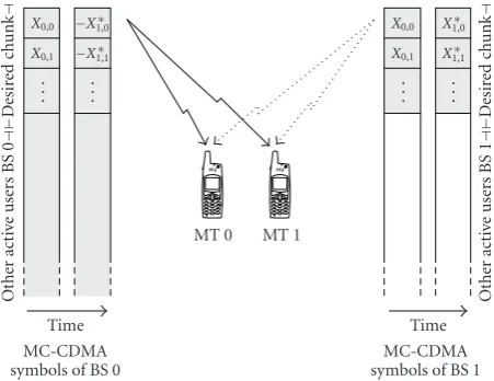
3.2. Cellular Alamouti technique (CAT)
In this section, we introduce the concept of transmit diversity by using the space-time block codes (STBCs) from orthogo-nal designs [7], namely, the Alamouti technique. We apply this scheme to the aforementioned cellular scenario. These STBCs are based on the theory of (generalized) orthogonal designs for both real- and complex-valued signal constella-tions. The complex-valued STBCs can be described by a ma-trix
wherelandNBSare the STBC length and the number of BS
(we assume a single TX-antenna for each BS), respectively. The simplest case is the Alamouti code [20],
B=
The respective assignment for the Alamouti-STBC to thekth block of chips containing data from one or more users is ob-tained:
conjugate complex yi(k)∗ at the receiver. At the receiver, the
vectory(k)is multiplied from left by the Hermitian of matrix
H(k). The fading between the different fading coefficients is
assumed to be quasistatic. We obtain the (weighted) STBC information symbols
x=H(k)H·y(k)=H(k)H·H(k)x+H(k)H·n(k)
=H(k)H·n(k)+x·1
i=0
h(i,k)2, (16)
corrupted by noise. For STBCs from orthogonal designs, MIMO channel estimation at the receiver is mandatory, that is, h(n,k), n = 0,. . .,N
BS−1, k = 0,. . .,K −1, must be
MC-CDMA symbols of BS 0
Time symbols of BS 1
Time
Figure6: MC-CDMA symbol design for CAT for 2 MTs.
estimated. Disjoint pilot symbol sets for the TX-antenna branches can guarantee a separate channel estimation for each BS [8]. Since the correlation of the subcarrier fading coefficients in time direction is decreasing with increasing Doppler spread—that is, the quasistationarity assumption of the fading is incrementally violated—the performance of this STBC class will suffer from higher Doppler frequencies. Later we will see that this is not necessarily true as the stationarity of the fading could also be detrimental in case of burst errors in fading channels.
Figure 6shows two mobile users sojourning at the cell
borders. Both users data is spread within one spreading block and transmitted by the cellular Alamouti technique using two base stations. The base stations exploit information from a feedback link that the two MTs are in a similar location in the cellular network. By this both MTs are served simultane-ously avoiding any interference between each other and ex-ploiting the additional diversity gain.
3.3. R´esum´e for C-CDD and CAT
at the critical cell border without the need of any informa-tion about the channel state informainforma-tion on the transmitter side. The main goal is to increase performance by avoiding interference and increasing diversity at the most critical en-vironment. In this case, the term C/I is misleading (cf. (6)), as there is noI(interference). On the other hand, it describes the ratio of the power from the desired base station and the other base station. This ratio also indicates where the mo-bile user is in respect to the base stations. For C/I = 0 dB the MT is directly between the two BSs, for C/I >0 dB the MT is closer to the desired BS, and for C/I<0 dB the MT is closer to the adjacent BS. Since the signals of the neighbor-ing BSs for the desired users are not seen as interference, the MMSE equalizer coefficients of (3) need no modification as in the intercellular interfering case [22]. Therefore, the trans-mit diversity techniques require no knowledge about the in-tercellular interference at the MT. By using C-CDD or CAT the critical cell border area can be also seen as a broadcast scenario with a multiple access channel.
For the cellular transmit diversity concepts C-CDD and CAT, each involved BS has to transmit additionally the sig-nal of the adjacent cell; and therefore, a higher amount of resources are allocated at each BS. Furthermore, due to the higher RL in each cell the multiple-access interference (MAI) for an MC-CDMA system is increased. There will be always a tradeoffbetween the increasing MAI and the increasing di-versity due to C-CDD or CAT.
Since the desired signal is broadcasted by more than one BS, both schemes can reduce the transmit signal power, and therefore, the overall intercellular interference. Using MC-CDMA for the cellular diversity techniques the same spread-ing code set has to be applied at the involved BSs for the de-sired signal which allows simple receivers at the MT with-out multiuser detection processes/algorithms. Furthermore, a separation between the inner part of the cells and the broadcast area can be achieved by an overlaying scrambling code on the signal which can be also used for synchronization issues as in UMTS [4].
Additionally, if a single MT or more MTs are aware that they are at the cell border, they could already ask for the C-CDD or CAT procedure on the first hand. This would ease the handover procedure and would guarantee a reliable soft handover.
We should point out two main differences between C-CDD and CAT. For C-C-CDD no changes at the receiver are needed, there exists no rate loss for higher number of trans-mit antennas, and there are no requirements regarding con-stant channel properties over several subcarriers or sym-bols and transmit antenna numbers. This is an advantage over already established diversity techniques [7] and CAT. The Alamouti scheme-based technique CAT should provide a better performance due to the coherent combination of the two transmitted signals [23].
4. RESULTING CHANNEL CHARACTERISTICS
FOR C-CDD
The geographical influence of the MT for CAT has a symmet-ric behavior. In contrast, C-CDD is influenced by the
posi-tion of the served MT. Due toδcyc0 =δ cyc
1 and the relation in
(11), the resulting performance regarding the MT position of C-CDD should have an asymmetric characteristic. Since the influence of C-CDD on the system can be observed at the receiver as a change of the channel conditions, we will investigate in the following this modified channel in terms of its channel transfer functions and fading correlation in time and frequency direction. These correlation characteris-tics also describe the corresponding single transmit antenna channel seen at the MT for C-CDD.
The frequency domain fading processes for different propagation paths are uncorrelated in the assumed qua-sistatic channel. Since the number of subcarriers is larger than the number of propagation paths, there exists correla-tion between the subcarriers in the frequency domain. The received signal at the receiver in C-CDD can be represented by
Since the interest is based on the fading and signal character-istics observed at the receiver, the AWGN termNl,iis skipped
for notational convenience. The expectation
Rl1,l2,i1,i2
yields the correlation properties of the frequency domain channel fading. Due to the path propagations α(dn) and
the resulting power variations, we have to normalize the channel transfer functionsHl(,ni)by the multiplication factor
1/NBS−1
n=0 α2(dn) which is included forRn(l,i).
The fading correlation properties can be divided in three cases. The first represents the power, the second investigates the correlation properties between the OFDM symbols (time direction), and the third examines the correlation properties between the subcarriers (frequency direction).
Case 1. Since we assume uncorrelated subcarriers the auto-correlation of the CTF (l1=l2=l,i1=i2=i) is
and the normalized power is
60
Figure7: Characteristic of correlation factorρover the subcarriers depending on the distanced0.
Case 2. The correlation in time direction is given by
l1=l2,i1 =i2 =i. Since the channels from the BSs are i.i.d.
We see that in time direction, the correlation properties of the resulting channel are independent of the MT position.
Case 3. In frequency direction (l1=l2=l,i1=i2) the
corre-lation properties are given by
Rl,i1=i2
component vanishes. And there is no beneficial increase of the frequency diversity close to a BS anymore. The normal-ized correlation properties yield
Rn
The correlation factorρis directly influenced by the C-CDD component and determines the overall channel corre-lation properties in frequency direction.Figure 7shows the characteristics ofρfor an exemplary system withNFFT=64, γ = 3.5,NBS =2,r =300 m,δcyc0 = 0, andδ
Figure8: Correlation characteristics over the subcarriers ford0 = [334 m, 335 m, 336 m].
Figure9: BER and SNR gains versus the cyclic delay at the cell bor-der (C/I=0 dB).
sample of the delay represents 320 microseconds or approx-imately 10 m, respectively. In the cell border area (200 m < d0 < 400 m), C-CDD increases the frequency diversity by
decorrelating the subcarriers. As mentioned before, there is less decorrelation the closer the MT is to a BS.
A closer look on the area is given inFigure 8where the in-herent delay and the added cyclic delay are compensated, that is, ford0=335 m the overall delay isδ1=δ(265 m) +δcyc1 = −70 m + 70 m=0 (cf. (11)). The plot represents exemplar-ily three positions of the MT (d0 = [334 m, 335 m, 336 m])
Table1: Parameters of the cellular transmission systems.
Bandwidth B 100.0 MHz
No. of subcarriers Nc 1664
FFT length NFFT 2048
Guard interval length NGI 128
Sample duration Tsamp 10.0 ns
Frame length Nframe 16
No. of active users Nu {1,. . ., 8}
Spreading lengh L 8
Modulation — 4-QAM, 16-QAM
Interleaving C-CDD — 2D
Interleaving CAT — 1D, 2D
Channel coding — CC (561, 753)oct
Channel coding rate R 1/2
Channel model — IEEE 802.11n Model C
Velocity — 0 mph, 40 mph
−10 0 10 20 30
C/I (dB) 1e−04
1e−03 1e−02 1e−01
BER
w/o TX diversity, fully loaded w/o TX diversity, half loaded C-DD, halved TX power C-CDD, halved TX power C-DD
C-CDD
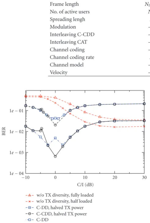
Figure10: BER versus C/I for an SNR of 5 dB using no transmit
diversity technique, C-DD, and C-CDD for different scenarios.
5. SIMULATION RESULTS
The simulation environment is based on the parameter as-sumptions of the IST-project WINNER for next genera-tion mobile communicagenera-tions system [24]. The used chan-nel model is the 14 taps IEEE 802.11n chanchan-nel model C with
γ=3.5 andτmax=200 nanoseconds. This model represents
a large open space (indoor and outdoor) with non-light-of-sight conditions with a cell radius ofr =300 m. The trans-mission system is based on a carrier frequency of 5 GHz, a bandwidth of 100 MHz, and an FFT length ofNc = 2048.
One OFDM symbol length (excluding the GI) is 20.48 mi-croseconds and the GI is set to 0.8 microseconds (corre-sponding to 80 samples). The spreading length Lis set to
8. The number of active users can be up to 8 depending on the used RL. 4-QAM is used throughout all simulations and for throughput performances 16-QAM is additionally inves-tigated. For the simulations, the signal-to-noise ratio (SNR) is set to 5 dB and perfect channel knowledge at the receiver is assumed. Furthermore, a (561, 753)8 convolutional code
with rateR = 1/2 was selected as channel code. Each MT moves with an average velocity of 40 mph (only for compar-ison to see the effect of natural time diversity) or is static. As described inSection 3, users with similar demands at the cell border are combined within time-frequency units. We assume i.i.d. channels with equal stochastic properties from each BS to the MT. If not stated otherwise, a fully loaded sys-tem is simulated for the transmit diversity techniques, and therefore, their performances can be seen as upper bounds. All simulation parameters are summarized inTable 1. In the following, we separate the simulation results in three blocks. First, we discuss the performances of CDD; then, the simula-tion results of CAT are debated; and finally, the influence of the MAI to both systems and the throughput of both systems is investigated.
5.1. C-CDD performance
Figure 9shows the influence of the cyclic delay δcyc1 to the
bit-error rate (BER) and the SNR gain at the cell border (C/I = 0 dB) for C-CDD. At the cell border there is no in-fluence due to C-DD, that is, (δ1 =0). Two characteristics
of the performance can be highlighted. First, there is no per-formance gain forδcyc1 =0 due to the missing C-CDD.
Sec-ondly, the best performance can be achieved for an existing higher cyclic shift which reflects the results in [25]. The SNR gain performance for a target BER of 10−3 depicts also the influence of the increased cyclic delay. For higher delays the performance saturates at a gain of about 2 dB.
−10 0 10 20 30 C/I (dB)
1e−05 1e−04 1e−03 1e−02 1e−01
BER
w/o TX diversity, fully loaded w/o TX diversity, half loaded CAT, halved TX power, 0 mph CAT, 0 mph, 2D interleaving CAT, 0 mph
CAT, 40 mph
Figure11: BER versus C/I for an SNR of 5 dB using no transmit
diversity and CAT for different scenarios.
0 0.25 0.5 0.75 1
Resource load 1e−04
1e−03 1e−02 1e−01
BER
C-CDD, C/I=10 dB CAT, C/I=10 dB
C-CDD, C/I=0 dB CAT, C/I=0 dB
Figure12: Influence of the MAI to the BER performance for vary-ing resource loads at the cell border and the inner part of the cell.
their separate MC-CDMA signal. FromFigure 9, we choose
δcyc1 = 30 samples and this cyclic delay is chosen
through-out all following simulations. The reference system is half (RL = 0.5) and fully loaded (RL = 1.0). We observe a large performance gain in the close-by area of the cell bor-der (C/I= −10 dB,. . ., 10 dB) for the new proposed diversity techniques C-DD and C-CDD. Furthermore, C-CDD en-ables an additional substantial performances gain at the cell border. The C-DD performance degrades for C/I=0 dB be-causeδ =0 and no transmit diversity is available. The same effect can be seen for C-CDD at C/I = −4.6 dB (δ1 = −30, δcyc1 = 30 ⇒ δ = 0); see alsoSection 4. Since both BSs in
C-DD and C-CDD transmit the signal with the same power
−10 0 10 20 30
C/I(dB) 0
20 40 60 80 100
M
ax
th
ro
u
gh
put
p
er
user
(%)
C-CDD, 4-QAM
C-CDD, halved TX power, 4-QAM w/o TX diversity, RL=0.5, 4-QAM w/o TX diversity, RL=1, 4-QAM C-CDD, 16-QAM
w/o TX diversity, RL=0.5, 16-QAM w/o TX diversity, RL=1, 16-QAM
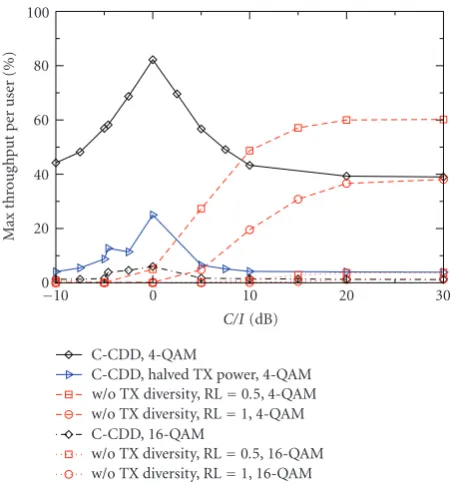
Figure13: Throughput per user for 4-QAM versus C/I using no
transmit diversity or C-CDD with full and halved transmit power.
as the single BS in the reference system, the received signal power at the MT is doubled. Therefore, the BER performance of C-DD and C-CDD atδ =0 is still better than the refer-ence system performance. For higher C/I ratios, that is, in the inner cell, the C-DD and C-CDD transmit techniques lack the diversity from the other BS and additionally degrade due to the double load in each cell. Thus, the MT has to cope with the double MAI. The loss due to the MAI can be di-rectly seen by comparing the transmit diversity performance with the half-loaded reference system. The fully loaded ref-erence system has the same MAI as the C-CDD system, and therefore, the performances merge for high C/I ratios. To es-tablish a more detailed understanding we analyze the C-CDD with halved transmit power. For this scenario, the total desig-nated received power at the MT is equal to the conventional MC-CDMA system. There is still a performance gain due to the exploited transmit diversity for C/I< 5 dB. The perfor-mance characteristics are the same for halved and full trans-mit power. The benefit of the halved transtrans-mit power is a re-duction of the intercellular interference for the neighboring cells. In the case of varying channel models in the adjacent cells, the performance characteristics will be the same but not symmetric anymore. This is also valid for the following CAT performances.
5.2. CAT performance
Figure 11shows the performances of the applied CAT in the
−10 0 10 20 30 C/I (dB)
0 20 40 60 80 100
M
ax
thr
oug
h
put
p
er
user
(%)
CAT, 4-QAM
CAT, halved TX power, 4-QAM w/o TX diversity, RL=0.5, 4-QAM w/o TX diversity, RL=1, 4-QAM CAT, 16-QAM
w/o TX diversity, RL=0.5, 16-QAM w/o TX diversity, RL=1, 16-QAM
Figure14: Throughput per user for 4-QAM and 16-QAM versus
C/I using no transmit diversity or CAT with full and halved transmit power.
cell border. If the MT moves with higher velocity (40 mph), the correlation of the subcarrier fading coefficients in time direction decreases. This incremental violation of the qua-sistationarity assumption of the fading is profitable compen-sated by the channel code. The total violation of the afore-mentioned constraint of CAT (cf.Section 3.2) is achieved by a fully interleaved (2D) MC-CDMA frame. There is a large performance degradation compared to the CAT performance with a noninterleaved frame. Nevertheless, a residual trans-mit diversity exists, the MT benefits at the cell border, and the performance is improved. The applied CAT is not only robust for varying MT velocities but also for non-quasistatic channel characteristics. Similar to C-CDD, there is still a per-formance gain due to the exploited transmit diversity for C/I<5 dB in the case of halved transmit powers at both BSs.
5.3. MAI and throughput performance of C-CDD and CAT
The influence of the MAI is shown inFigure 12. The BER performance versus the resource load of the systems is pre-sented. Two different positions of the MT are chosen: di-rectly at the cell border (C/I = 0 dB) and closer to one BS (C/I =10 dB). Both transmit diversity schemes suffer from the increased MAI for higher resource loads which is in the nature of the used MC-CDMA system. CAT is not influenced by the MAI as much as C-CDD for both scenarios. Both per-formances merge for C/I = 10 dB because the influence of the transmit diversity techniques is highly reduced in the in-ner part of the cell.
Since we assume the total number of subcarriers is equally distributed to the maximum number of users per cell,
each user has a maximum throughput ofηmax. The
through-putηof the system, by using the probabilityP(n) of the first correct MC-CDMA frame transmission aftern−1 failed re-transmissions, is given by
η=
∞
n=0 ηmax
n+ 1P(n)≥ηmax(1−FER). (24)
A lower bound of the system is given by the right-hand side of (24) by only consideringn= 0 and the frame-error rate (FER). Figures13and14illustrate this lower bound for dif-ferent modulations in the case of C-CDD and CAT.
C-CDD inFigure 13outperforms the conventional sys-tem at the cell border for all scenarios. Due to the almost van-ishing performance for 16-QAM with halved transmit power for an SNR of 5 dB, we do not display this performance curve. For 4-QAM and C-CDD, a reliable throughput along the cell border is achieved. Since C-CDD with halved transmit power still outperforms the conventional system, it is possible to de-crease the intercellular interference.
The same performance characteristics as in C-CDD re-garding the throughput can be seen inFigure 14for applying the transmit diversity technique CAT. Due to the combina-tion of two signals in the Alamouti scheme, CAT can pro-vide a higher throughput than C-CDD in the cell border area. The CAT can almost achieve the maximum possible through-put in the cell border area. For both transmit diversity tech-niques, power and/or modulation adaptation from the BSs opens the possibility for the MT to request a higher through-put in the critical cell border area. All these characteristics can be utilized by soft handover concepts.
6. CONCLUSIONS
This paper handles the application of transmit diversity tech-niques to a cellular MC-CDMA-based environment. Ad-dressing transmit diversity by using different base stations for the desired signal to a mobile terminal enhances the macro-diversity in a cellular system. Analyses and simulation re-sults show that the introduced cellular cyclic delay diversity (C-CDD) and cellular Alamouti technique (CAT) are capa-ble of improving the performance at the severe cell borders. Furthermore, the techniques reduce the overall intercellu-lar interference. Therefore, it is desirable to use C-CDD and CAT in the outer part of the cells, depending on available re-sources in adjacent cells. The introduced transmit diversity techniques can be utilized for more reliable soft handover concepts.
ACKNOWLEDGMENTS
REFERENCES
[1] IST-2003-507581 WINNER Project, https://www.ist-winner .org.
[2] S. Plass, “On intercell interference and its cancellation in cellu-lar multicarrier CDMA systems,”EURASIP Journal on Wireless Communications and Networking, vol. 2008, Article ID 173645, 11 pages, 2008.
[3] D. Wong and T. J. Lim, “Soft handoffs in CDMA mobile sys-tems,”IEEE Personal Communications, vol. 4, no. 6, pp. 6–17, 1997.
[4] M. Schinnenburg, I. Forkel, and B. Haverkamp, “Realization and optimization of soft and softer handover in UMTS net-works,” inProceedings of European Personal Mobile Communi-cations Conference (EPMCC ’03), pp. 603–607, Glasgow, UK, April 2003.
[5] A. Wittneben, “A new bandwidth efficient transmit antenna modulation diversity scheme for linear digital modulation,” inProceedings of IEEE International Conference on Communi-cations (ICC ’93), pp. 1630–1634, Geneva, Switzerland, May 1993.
[6] A. Dammann and S. Kaiser, “Performance of low complex antenna diversity techniques for mobile OFDM systems,” in Proceedings of International Workshop on Multi-Carrier Spread Spectrum (MC-SS ’01), pp. 53–64, Oberpfaffenhofen, Ger-many, September 2001.
[7] V. Tarokh, H. Jafarkhani, and A. R. Calderbank, “Space-time block codes from orthogonal designs,”IEEE Transactions on Information Theory, vol. 45, no. 5, pp. 1456–1467, 1999. [8] M. Inoue, T. Fujii, and M. Nakagawa, “Space time transmit
site diversity for OFDM multi base station system,” in Proceed-ings of the 4th EEE International Workshop on Mobile and Wire-less Communication Networks (MWCN ’02), pp. 30–34, Stock-holm, Sweden, September 2002.
[9] S. B. Weinstein and P. M. Ebert, “Data transmission by frequency-division multiplexing using the discrete Fourier transform,” IEEE Transactions on Communications, vol. 19, no. 5, pp. 628–634, 1971.
[10] Z. Wang and G. B. Giannakis, “Wireless multicarrier commu-nications: where Fourier meets Shannon,”IEEE Signal Process-ing Magazine, vol. 17, no. 3, pp. 29–48, 2000.
[11] M. Sternad, T. Svensson, and G. Klang, “The WINNER B3G system MAC concept,” inProceedings of IEEE Vehicular Technology Conference (VTC ’06), pp. 3037–3041, Montreal, Canada, September 2006.
[12] K. Fazel and L. Papke, “On the performance of concolutionally-coded CDMA/OFDM for mobile com-munications systems,” in Proceedings of IEEE International Symposium on Personal, Indoor and Mobile Radio Communica-tions (PIMRC ’93), pp. 468–472, Yokohama, Japan, September 1993.
[13] N. Yee, J.-P. Linnartz, and G. Fettweis, “Multi-carrier CDMA for indoor wireless radio networks,” in Proceedings of IEEE International Symposium on Personal, Indoor and Mobile Ra-dio Communications (PIMRC ’93), pp. 109–113, Yokohama, Japan, September 1993.
[14] K. Fazel and S. Kaiser,Multi-Carrier and Spread Spectrum Sys-tems, John Wiley & Sons, San Francisco, Calif, USA, 2003. [15] A. Viterbi, “Error bounds for convolutional codes and an
asymptotically optimum decoding algorithm,”IEEE Transac-tions on Information Theory, vol. 13, no. 2, pp. 260–269, 1967. [16] A. Dammann and S. Kaiser, “Transmit/receive-antenna diver-sity techniques for OFDM systems,”European Transactions on Telecommunications, vol. 13, no. 5, pp. 531–538, 2002.
[17] G. Auer, “Channel estimation for OFDM with cyclic de-lay diversity,” in Proceedings of IEEE International Sympo-sium on Personal, Indoor and Mobile Radio Communications (PIMRC ’04), vol. 3, pp. 1792–1796, Barcelona, Spain, Septem-ber 2004.
[18] G. Bauch, “Differential modulation and cyclic delay diversity in orthogonal frequency-division multiplex,” IEEE Transac-tions on CommunicaTransac-tions, vol. 54, no. 5, pp. 798–801, 2006. [19] G. L. St¨uber,Principles of Mobile Communication, Kluwer
Aca-demic Publishers, Norwell, Mass, USA, 2001.
[20] S. M. Alamouti, “A simple transmit diversity technique for wireless communications,”IEEE Journal on Selected Areas in Communications, vol. 16, no. 8, pp. 1451–1458, 1998. [21] D. Tse and P. Viswanath,Fundamentals of Wireless
Communi-cation, Cambridge University Press, New York, NY, USA, 2005. [22] S. Plass, X. G. Doukopoulos, and R. Legouable, “On MC-CDMA link-level inter-cell interference,” inProceedings of the 65th IEEE Vehicular Technology Conference (VTC ’07), pp. 2656–2660, Dublin, Ireland, April 2007.
[23] H. Schulze, “A comparison between Alamouti transmit di-versity and (cyclic) delay didi-versity for a DRM+ system,” in Proceedings of International OFDM Workshop, Hamburg, Ger-many, August 2006.
[24] IST-2003-507581 WINNER, “D2.10: final report on identified RI key technologies, system concept, and their assessment,” December 2005.