R E S E A R C H
Open Access
Cascading polar coding and LT coding for
radar and sonar networks
Liping Jin
1,2, Youming Li
2*, Chenglin Zhao
3, Zhuanghun Wei
3, Bin Li
3and Jiong Shi
1Abstract
In radar and sonar networks, heavy clutter and noise have generated strong impairments to information transmission and processing. Coding techniques have been widely used to cope with various channel noises and thereby to improve transmission performance. In the study, we investigate a novel cascaded coding scheme for systems operating in adverse electromagnetic environments, e.g., underwater acoustic communications (UAC), where the impulsive noise will be inevitable and the bit error ratio (BER) of receiver will be deteriorated greatly. Our cascaded encoding scheme employs the polar code as inner code while the Luby transform (LT) code as outer code. Inspired on a novel conception of channel polarization, the polar code uses a group of idea sub-channels to carry the useful information, while let other bad sub-channels bear no information. By cascading the outer LT code which
accomplishes some parity check to the input of inner code, the performance of inner polar code is improved, as the decoding of polar code relies on a successive cancelation technique which is relatively sensitive to initial input. Error correcting performance of the new cascaded code is studied under impulsive noise characterized by a Middleton Class-A model. Simulations validate the proposed cascaded coding scheme. Compared with the popular low-density parity check (LDPC) code, the cascaded scheme can significantly improve the BER performance in the presence of impulsive interference, which also surpasses another cascaded code that is proved to be effective in impulsive noise channel, i.e., cascaded LDPC and LT coding scheme.
Keywords: Impulsive noise, Polar code, LT code, Middleton Class-A model
1 Introduction
In radar and sonar networks, heavy clutter and noise have generated strong impairments to information trans-mission and processing [1]. Information processing in radar and sonar networks is critical in target detection and recognition [2]. For example, in radar sensor net-works, waveform diversity is the technology that allows one or more sensors on board a platform to automati-cally change operating parameters, e.g., frequency, gain pattern, and pulse repetition frequency (PRF), to meet the varying environments. It has long been recognized that judicious use of properly designed waveforms, coupled with advanced receiver strategies, is fundamental to fully utilize the capacity of the electromagnetic spectrum [3, 4]. As a result, there are emerging and compelling changes in system requirements such as more efficient spectrum
*Correspondence: [email protected]
2College of Information Science and Engineering, Ningbo University, No. 818, Fenghua Road, 315211, Ningbo, China
Full list of author information is available at the end of the article
usage, higher sensitivities, greater information content, improved robustness to errors, and reduced interference emissions. The combination of these changes is fueling a worldwide interest in the subject of waveform design and the use of waveform diversity techniques [5]. Wave-form diversity introduces redundancy in the spatial or time domain. In this paper, we are interested in introduc-ing redundancy in the bit domain and study cascadintroduc-ing polar coding and LT coding for radar and sonar networks with impulsive noisy channels.
In sharp contrast to the thermal noise that is usually modeled by Gaussian noise, impulsive noise is another commonly encountered channel noise in various sys-tems which involves instantaneous or impulse-like sharp sounds [6, 7]. Such impulsive noise will be aroused by the sudden change of either electric devices or electromag-netic environments. For example, in underwater acoustic communications (UAC) [8, 9], the random impulsive noises can be generated by marine creatures such as shrimps [10]. For other communication systems, e.g.,
power line communications (PLC) [11, 12], the impulsive noise can be aroused by the frequent on/off cycle of many distributed contactors. Usually, the impulsive noise will bring some devastating consequences to the information recovering of the UAC and PLC systems [13, 14].
Due to the high spectral efficiency and high data rate, the orthogonal frequency division multiplexing (OFDM) has been widely used in both military and commer-cial communications, e.g., UAC and PLC [15, 16]. It is shown that OFDM system has the inherent immunity to frequency-selecting channel fading, which divides the broad band into multiple narrow sub-bands with the help of simple channel estimation algorithms. However, impul-sive noise occurring in time domain can cause serious signal distortions in OFDM systems which are extremely sensitive high signal peaks [14, 17]. To be specific, when the random amplitude of impulsive noises exceeds some extents, then an enormous loss in BER performance will occur in OFDM receiver, which is aroused by the energy spread of impulsive noise into multiple carriers after OFDM demodulation. So, one of the major challenges in designing UAC or PLC system is how to effectively com-bat the negative effects of impulsive noise and promote the BER performance [13, 14, 18].
Existing methods used to detect and remove impul-sive noises include blanking, clipping or deep clipping etc. [19, 20]. Unfortunately, it is still infeasible to detect the impulse noise effectively and timely in the time domain, due to the instantaneous nature of impulsive noises and the unaffordable computational and hardware complexity. As suggested in [18], channel coding seems to be another feasible approach, which corrects the errors caused by additive channel noises and hence promote the data trans-mission performance. In [21] and [22], the well-known LDPC is firstly applied to the impulse noise channel, which is fully characterized by a parity check matrix (PCM) [23, 24]. As demonstrated, the LDPC scheme has achieved better performance which is further cascaded with Luby transform (LT) code [25, 26], even in the presence of challenging impulsive noises. However, the drawback with LDPC codes is the exponential increase with code length in implementation complexity. Recently, a polar code scheme is suggested to combat impulsive noise, which is shown to be effective in correcting the errors caused by impulsive noises and is also superior to the widely used LDPC and LT code.
Although the application of a single PC scheme to deal with impulsive noises has been studied in our previous work [18], there is no literature reported explicitly in the context of more effective cascaded coding scheme. In this paper, we proposed a new successive cascaded cod-ing scheme to enhance the error-correctcod-ing capability in the presence of impulsive noises. The proposed cascaded encoding scheme employs the polar code as inner code
and the LT code as outer code. As suggested in [27], premised on a novel conception of channel polarization, the inner polar code (PC) can divide the whole channel into multiple sub-channels via recursively channel comb-ing and splittcomb-ing and then use some good channels to transmit useful information. It is noted that, however, a single polar code is sensitive to impulsive noise which could cause the error spreading in the time domain, due to the energy spreading of impulse noise after the DFT oper-ation [18]. In our cascaded coding scheme, other than fed directly to the PC encoder, the low-complexity LT code is used to perform parity check as a first-step outer decoder. Although the LT code has limited error-correcting capa-bility, a slight BER decrease in the input sequence will greatly enhance the decoding performance of PC. This is not surprise, as the PC decoder essentially utilizes the successive interference cancelation scheme and the initial result will have remarkable influence on the subsequent decoding process. By further integrating a matrix inter-leave operation in the inner PC encoder, the cascaded coding scheme can acquire significantly improved BER performance by imposing some slight encoding/decoding complexity, which in fact provides a great compromise between the error-correcting capacity and implementa-tion complexity.
To sum up, the main contributions of our investigation can be summarized to the following three aspects:
1. We propose to use a low-complexity LT code to perform simple parity check on the received signal. 2. We propose to use the polar code as the inner code,
therefore suggesting a new cascaded coding scheme to improve the BER performance of the OFDM system in the context of impulsive noise.
3. We compare the error-correcting performance of both the proposed cascaded code scheme and traditional single PC or LDPC coding scheme and the existing cascaded LPDC-LT coding scheme in the presence of realistic impulsive noises.
The rest of this investigation is listed as follows. Section 2 describes the system model of OFDM. The impulsive noise model is also discussed. Then, in Section 3, the basic idea of cascading code is introduced, which is then applied to the impulsive noisy channel. Experimental simulations and performance evaluations are provided in Section 4. The whole investigation is finally concluded in Section 5.
2 System model
2.1 OFDM communications system
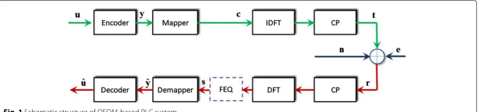
Fig. 1Schematic structure of OFDM-based PLC system
an encoder module. Then, the coded signalsywill pass through a modulation modular, which produces the base-band complex signalscof special magnitudes and phase characteristics. The high-order modulations like QPSK and 16-QAM, in which the amplitude and phase are joint modulated, are widely used in order to improve the spec-tral efficiency. Next, the multiple carrier modulation is accomplished via the inverse discrete Fourier transform (IDFT). After adding the cyclic prefix (CP), the generated OFDM signalstare emitted into the noisy channel.
The emitted signals will be corrupted by two kinds of channel noises. The first one, i.e., the additive white Gaussian noise n, is common to many communication systems. The second one, i.e., impulsive noise e, how-ever is prominent to acoustic communications or power line communication systems. The received signals, after removing CP, will be recovered based on some operations corresponding to the transmitter structure. Notice that the frequency-domain channel equalizer will be adopted to combat the effects of frequency-selective fading. As far as the main objective of the study is concerned, i.e., the error correcting coding method under realistic impulsive noises, we assume the multipath channel response can be estimated and calibrated via a FEQ modular. Then, we may focus on how the coding scheme can improve the BER performance in the presence of impulsive interfer-ences.
2.2 Impulsive noise
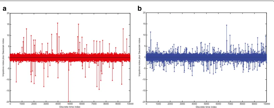
The random and sudden state transients in electromag-netic conditions, such as the unpredictable activities of marine creatures (such as shrimps) in acoustic commu-nications [10, 28], or the appliance electric switching or other uncoordinated transmissions in PLC systems [12, 29], will probably lead to impulsive noise. The result-ing impulsive noises, despite the sparsity in the time domain, usually have the extremely strong power, which will significantly degrade the transmission performance of OFDM systems that are sensitive to amplitude distortions. Statistical models on the impulsive noise will include the Gaussian mixture model (GMM), Middleton Class-A model, Symmetric Class-Alpha-Stable (S-S) models [30],
Markov chains model [31], and Markov-Gaussian model [32], which can all conform to the measurement data from various aspects. Among these models, the Middleton Class-A model has been most commonly used [33] due to the following three considerations. First, the Middleton Class-A model is canonical, which assumes the indepen-dent impulse emissions Poisson-distributed in space and time and therefore will be invariant of particular physical source mechanisms. Second, since a Middleton Class-A model is premised on the first-order statistics of impulsive noises, it exhibits a simple probability density function (PDF), which depends only on few physical parameters and hence can facilitate the analysis significantly. Third, this work focuses primarily on the error-correcting per-formance of various encoding schemes in impulsive noisy environments, so the time domain correlation carried by the Markov chains model, e.g., Markov-Gaussian model, will be unnecessary in our analysis, which, however, may provide some additional information for the optimizing the practical designing of receivers/detectors [34, 35] (e.g., the pilot sequences and the channel estimators).
According to the Middleton Class-A model [30], the probability density function (PDF) of random impulsive noises is
τ ranges from 10−6 to 1; A represents the overlapping factor ranging from 0.01 to 1, which accounts for the mul-tiplication of the average transmission and the average interval.
From Eq. (2), the Middleton Class-A model can be viewed as a special case of the GMM distribution, i.e.,
p(i)= lim
a
b
Fig. 2Simulated channel noise with impulsive interferences of the Middleton Class-A impulsive noise.aThe overpapping factor is 0.01 and the power ratio is 1.bThe overlapping factor is 0.05 and the power ratio is 1
also clearly observe the influences of the overlapping fac-torAon the time characteristics of impulsive noises. The smaller the overlapping factorA(e.g.,A=0.01), the more sparse the impulsive noise, yet with the stronger impulsive power.
2.3 LDPC coding scheme
As a powerful error-correcting tool, LDPC codes has been applied widely in PLC in order to combat the encountered impulsive noises [21, 22]. As LDPC code is associated with the subgroup of linear block codes (LBC), it is also speci-fied by a designed parity check matrix (PCM) denoted by H[23, 24]. Usually, this PCM of LDPC is a sparse matrix. Given the codeword denoted by y, then the following constraint relationship can be applied
HyT =0. (3)
Note that the PCM of the(n−k)×ndimension results in a coding rate ofk/n. Another well-known feature of LDPC codes is that a structured shape exists in this PCM, i.e., a bipartite graph, which can be properly utilized to facilitate the decoding in the receiver.
3 Cascaded coding scheme
In the investigation, we will introduce a less complex error-correcting code, that is PC to PLC systems and study its performance in the context of impulsive noises, which remain quite different from the widely assumed Gaussian noises of wireless communications.
3.1 Polar coding
Polar code is known as the first provable capacity-achieving code in memoryless channels. Inspired by the conception of channel polarization [27], the polar code
scheme will divide the end-to-end channel into a series of sub-channels. Such virtual sub-channels will possess different transmission qualities, i.e., some sub-channels may be capable of the excellent transmission quality and can provide errorless transmissions, while the remain-ing sub-channels have the high error ratio approachremain-ing 0.5. So, the polar encoder will exploit such two polarized sub-channels, which will differ essentially from a com-mon sense of polarizations in the electromagnetic field. If the channel is polarized based on some dividing strategy, then encode process will be straightforward. The use-ful information will be load to the virtual channels with the excellent quality, while the frozen bits (i.e., the use-less padding information) will be padded into other bad sub-channels.
In order to polarize the channel, according to the Arikan’s original work [27], usually the recursive combin-ing and splittcombin-ing process will be implemented. In the first stage, totalN virtual sub-channels are combined. Then, in the second stage these combined channels will be split-ted into N new sub-channels. After each recursion, the transmission capacity of good channels will be further improved, while the capacity of bad channels will be grad-ually degraded. Finally, the channel will be polarized to good sub-channels with ideal transmission capacity of 1 and the others bad sub-channels with worst capacity of 0. Relying on the channel combining and splitting, the encoding and decoding scheme of PC scheme can be obtained.
3.1.1 Encoding
Letl =2, as shown in [27], a transition matrix is defined as
F=
1 0 1 1
With a fixed inputting length N = 2m, a generator matrixGNcan be calculated from
GN =RlN(F⊗GN/l). (4) Here, G1 represents a unit matrix, and⊗denotes the Kronecker multiplication between two matrixes; RlN is known as the bit-reversal permutation (BRP) matrix, see [27] for more details. Premised on the generator matrix GN, the encoding process will resemble other traditional linear coding schemes, i.e., the output encoding sequence isx = uGN, whereuN0−1 =[u0 u1. . .uN−1]T accounts for the input information sequence of the lengthN.
3.1.2 Decoding
Denotes the index set of all frozen positions withAf, then the decoder will focus on the information bearing posi-tions need to be estimated, i.e.,i ∈ Af, rather than the frozen positions, i.e.,i∈Af. Given the likelihood of theith position conditioned on the recovered informationui0−1, the decoding process will be specified by
ui=
The successive cancelation (SC) scheme has been widely [36, 37] recommended to decoding the received sequence. A underlying conception is that a decoder will firstly calculate the likelihood ratio of ui, conditioned on the channel output yN0 and the already recovered uˆi0−1 = [uˆ0 uˆ1. . .uˆi−1]T. In the manner, by canceling the inter-ference from the last estimated symbols, the current position can be properly decoded.
If we denote the transitional probability of theith polar-ized sub-channel with WNi
yN0,ui0−1|ui=0
, which are computed via a recursive manner after channel splitting, then the conditioned likelihood is
LiN
Relying on the conditioned likelihood, the estimation process is specified by
In practice, the butterfly architecture can be utilized to calculate effectively the likelihood ratios, by further speeding up the decoding process and reducing the latency. Denote two sub-sets of u20i−2 with the odd
When l > 2, the extended encoding and decoding scheme should be given. Fortunately, in the recent work, the high-order case (e.g., l = 3) for PC has been stud-ied. In [36], a generalized channel combination and slip-ping scheme has been provided and, simultaneously, the decoding scheme has also been designed. It is noted that, compared withl = 2, the extended scheme (i.e.,l = 3) leads to the less implementation complexity.
3.2 LT coding
As a first realization of a class of erasure code [26], LT code is essentially premised on the Luby transform and belongs to the category of Fountain codes. The wide appli-cation of LT code is attributed to three major merits [38, 39]. Firstly, the LT code is rate-less and therefore it will be especially suitable to link rate adaptation scenarios. In other words, the encode length is not restricted by a finite coding rate and it can be as many as needed. Secondly, the erasure essence of the LT code allow us to decode from a small set of received symbols, which is well suited for propagation channels with high errors, such as the impulsive interference scenario. Thirdly, a distinguishing characteristic of the LT code is the low implementation complexity [40]. In sharp contrast to the multiplication and even matrix operations, only the exclusive OR oper-ation will be required in both the encoding and decoding processes [26], making the LT code attractive to some low-complexity applications.
3.2.1 Encoding
One of the most important innovations in the LT code is the degree distribution. Given the input bitbnof the cur-rent durationk, the degree will assign randomly a piece of distinct neighbors among the input sequence, which will then be taken into the encoding symbol. According to [26], if the block length of the input bits is k, then the degree distributionρ(d)can be specified by an ideal Soliton distribution (ISD), i.e.,
ρ(d=i)=
1/k, i=1,
probability. As an alternative, another robust Soliton dis-tribution (RSD) has been widely recommended [26].
If we defineR = c√kln(k/δ), then a common RSD is
where c > 0 is a constant, δ also accounts for a small positive value.
Given the specific degree densityμ(d=i), the encoding process will be relatively straightforward, which mainly involves the following three steps:
1. select a random degree according to the distribution, i.e.,d∼μ(d=i);
2. chooseddistinct neighbors around the current input bitbkin a uniform manner, which are denoted by
b(k1),bk(2),. . .,b(kd);
3. calculate the exclusive-OR of thed-neighbors and finally output the encoder symbol.
According to the above elaborations, the encoding symbol of the timekis given by
ck=b(k1)⊕bk(2)⊕. . .⊕b(kd). (12)
3.2.2 Encoding
The decoding process of LT code relies on the a pri-ori degree distribution, i.e., μ(d = i), as well as the neighborhood relation between the received symbols. The underlying rule is to release recursively the symbol from a ripple until it contains no symbols [26]. In the con-text of LT decoding, the ripple contains many covered but not processed symbols. The detailed decoding process is described as
1. The symbols with one neighbor will be firstly released, and meanwhile, its neighbor will be covered with it and put into a ripple.
2. Then, an input symbol in the ripple will be processed. That means, it will be removed as a neighbor from all the encoding symbols.
3. The neighbors will be released if they have only one neighbor (with a degree ofd=1), and the neighbors of this released symbols will be also covered and put into the ripple.
4. If all the encoding symbols have been covered, and at the end of recursion, the ripple will become empty in the idea case. Then, the decoding process succeeds and the decoded sequence will be output. Otherwise, return to step 2. If there is at least one uncovered
symbol, then the decoding process fails. Note that in the situation of decoding failure, then the received sequence will not be processed and directly fed to the subsequent processor.
3.3 Cascaded coding scheme
The major effect of impulsive interferences is the sud-den and strong distortion on received symbols. This may arouse the burst decoding errors, which can be the formidable challenge to the decoding of non-erasure code in which the encoding constraint length is very larger. As a consequence, the error-correcting performance of clas-sical non-erasure codes will be degraded in the presence of the impulsive interference. Due to the long constraint length, the polar code may also suffer from impulsive interferences. As shown in [18], although it will promote the error-correcting performance in impulsive interfer-ence scenarios compared with the LDPC, there is still some space to improve its decoding performance.
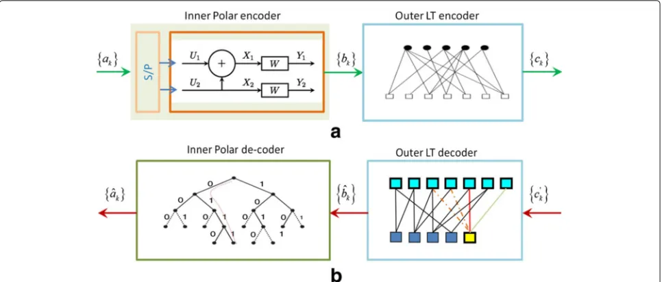
An observation on BER curves of the polar code indi-cates that, only the SNR surpass the threshold, can the decoding error decreased remarkably. That means, the property of input sequence will greatly affect its decoding performance. This is easy to understood, i.e., the decoding strategy of polar code is essentially based on a successive cancelation technique, and the remarkable initial errors (or distortions) will be propagated in the decoding pro-cess, resulting in the unfavorable performance. So, we suggest combining the LT code and polar code together to further combat the impulsive interference. The encoder and decoder structure of the proposed new cascading code is illustrated in Fig. 3.
Fig. 3 aEncoder structure of the cascading code.bDecoder structure of the cascading code
4 Numerical simulations
In this section, the error-correcting performance of the proposed cascading code scheme will be evaluated in the impulsive interference channels. In the simulations, we mainly focus on the transmission performance of OFDM-based communication systems with different cod-ing schemes. As we have indicated, the investigation focuses primarily on the cascading code scheme in impul-sive noises, for the simplicity of analysis, it is assumed that the frequency-selective channel has already been esti-mated and equalized. The Middleton Class-A impulsive noise model is considered. For the PC scheme, we choose uAf as a 0 vector. In the analysis, the classical polar code
(i.e., l = 2) is adopted. Meanwhile, the LDPC scheme approved by many commercial standards has also been adopted. The constraint length of both PC and LDPC is configured to be 512. For the matrix interleaving process, k1 = 512 andk2 = 391. For the purpose of compar-ative analysis, both LDPC code and PC use this matrix interleaving operation in the experimental simulations.
4.1 Effects of parameter configurations
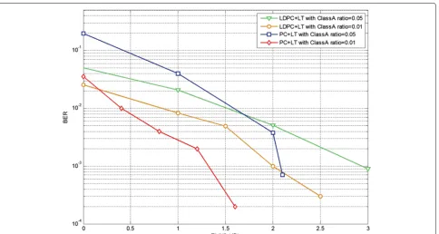
In the first simulation, the benefit of interleaving opera-tions is investigated and the simulation results are plotted in Fig. 4. We can find that compared to the LDPC+LT cascading coding scheme, the polar+LT cascading code will obtain more gains from the interleaving operation. For example, when the BER is 10−2, the polar+LT cas-cading code can be improved by 1.35 dB when adopting the interleaving operation. However, the other LDPC+LT coding scheme can only achieve 0.4 dB. So, the inter-leaving operation is of promise to the proposed polar+LT code scheme. The underlying reason is that, after the FFT
operation in the receiver, the impulsive interference will affect a piece of input sequences, which may seriously deteriorate the decoding of the inner polar code. Using the interleaving can alleviate the above effects and thereby promote the BER performance of polar+LT code.
Note that, as the interleaving operation is mainly inte-grated to disperse the input errors that are contiguous, other configurations to an interleaving depth (i.e., k1) will also be feasible. For example, in Fig. 4, the BER curve of another depthk1 = 1024 are further provided, and the similar conclusions will be obtained. In prac-tice, a compromise should be made between the decoding performance and the implementation complexity when setting this parameter. In general, the long interleaving length will promote the performance, which, on the other hand, will lead to extra time delay and increased memory requirements.
Besides, due to the sensitiveness on input symbols, in low SNR region (e.g.,<0.2 dB) the decoding performance of PC scheme will be inferior to the other LDPC scheme. That is, the error propagation in successive cancelation process will be very serious, when the input symbols are seriously contaminated.
Fig. 4Effects of interleaver on the BER performance of the new cascading code
4.2 Performance comparison
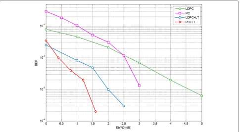
In Fig. 6, we further compared the new polar+LT cas-cading code with other existing coding schemes. In this simulation, the power ratio of impulsive noise is 0.1. The coding rate of both LDPC and polar code is 1/2. We can observe from the simulation results that, by combing the outer LT code, the proposed polar+LT code can achieve the best error-correcting performance in the presence of impulsive noises. Compared with the recently studied polar code, the new cascading scheme can achieve about 1.7dB when the BER drops to 10−3.
Compared with the other cascading benchmark, i.e. LDPC+LT code, when the constraint length is also config-ure to 512, we note from Fig. 7 that a rough gain of 1dB can be obtained when the BER drops below 3×10⁻⁴. Mean-while, the complexity of the new cascading code is much lower than the benchmark LDPC+LT code. According to Jin et al. [18], the encoding implementation complexity of LDPC+LT will beO(N2)+O(log2(N/δ)), and its decod-ing complexity isO(Nlog2N) +O(Nlog2(N/δ)), when the popular belief-propagation (BP) scheme for LDPC is concerned. And for the new polar+LT code, the decoding complexity isO(Nlog2N)+O(Nlog2(N/δ)).
For the inner PC scheme, there will also exist other decoding techniques. For example, a successive cancela-tion list (SCL) decoder [41], which searches for the most likely decoding paths concurrently at each decoding stage, will achieve the more promising decoding performance,
which, however, requires the higher complexity in imple-mentations. The optimal decoding schemes, such as the maximum likelihood (ML) or maximum a posterior (MAP) [42] decoders which can be implemented via the Viterbi and BCJR algorithms on the trellis, will suffer from the unaffordable complexity in practice. As has been men-tioned, the successive cancelation scheme, as a simplified implementation of a BP concept, is used to decode PC. For its counterpart LDPC scheme, the BP decoding scheme is also adopted in the analysis. Therefore, the decoding algo-rithms of both PC and LDPC will be premised on a similar recursive framework. It should be noted that, when adopt-ing the original BP technique, the error-correctadopt-ing perfor-mance of PC can be further improved, compared with the currently simplified successive cancelation scheme.
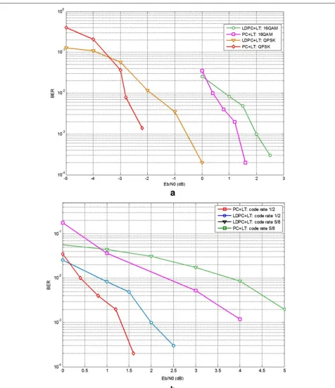
Finally, the BER performance of the new polar+LT code is evaluated in the different transmission config-urations. In the simulation, the power ratio is 0.1. In Fig. 7a, the error-correcting performances under QPSK and 16QAM are plotted. We can note that, with the lower-order modulation, the advantage of the cascading polar+LT code will be more obvious, when compared with its counterpart LDPC+LT code. For example, when the BER is 2×10⁻³, the performance gain achieved by the new polar+LT code is about 1.75 dB for QPSK, while this decoding gain will be 0.8 for 16QAM. In Fig. 7b, the error-correcting performances under different coding rate are demonstrated. It is found from simulation results that,
Fig. 7BER performance of different modulation formats. The impulsive ratio is set to 0.01.aDifferent modulation schemes andbdifferent coding rate when 16QAM is assumed and impulsive ratio is set to 0.01
with the higher coding rate, the performance gain of the polar+LT code will be more obvious. To be specific, when the coding rate is 5/8 and the BER is 2×10⁻³, the per-formance gain achieved by the polar+LT code is about
a consequence, the continuous errors in initial input symbols will cause the error propagation inevitably, and thereby degrade the error-correcting performance seri-ously. To combat the challenge, two techniques are designed to enhance the decoding performance in the context of impulsive interferences. First, the interleave operation is introduced to transform the continuously contaminated symbols into some dispersive errors, which will alleviate the error propagations in decoding to some extents and may eliminate the error floor, as demon-strated by Fig. 4. Second, with the assistance of the outer code (i.e. LT), the errors of inputting symbols will be further reduced, which will effectively improve the error-correcting performance of the new cascaded LT+PC scheme.
Owing to its powerful error-correcting ability, the PC scheme will be particularly useful to some adverse propagation conditions, e.g., the concerned impulsive interference environments. Due to the following two con-siderations, another LT code is adopted as an outer code. First, the erasure nature of the LT code agrees well with the sudden impulsive noises, which will only affect a small portion of input symbols. Second, the sim-ple encoding/decoding algorithm will impose a slight computation burden to the whole cascaded scheme, which makes it more attractive for real applications. The decoding benefit will be remarkable especially in high SNRs. It should be note that, from Fig. 6, the BER performance of our cascaded scheme will be sharply decreased if the SNR is smaller than a threshold, e.g., 0 dB. In future research, more effective iterative decod-ing mechanism will be investigated to further promote the performance.
5 Conclusions
In this investigation, we proposed a cascading code scheme to combat the non-Gaussian impulsive noise channel, which is commonly encountered in some mil-itary communications, e.g. UAC systems. Our cascaded encoding scheme employs the polar code as inner code while the Luby transform (LT) code as outer code. Based on the low-complexity parity check operations, the outer code will improve the input of inner polar code. As a result, the error-correcting performance of the proposed cascading polar+LT code can be significantly improved in the impulsive noises. More importantly, this advantage is achieved without remarkable increase in implementation complexity. The numerical derived BER performance fur-ther validates the proposed cascading scheme, which can significantly surpass the exsiting LDPC+LT code scheme. Thus, the new code scheme will be of great promise to some communication applications, such as radar and UAV communications, which are characterized by impulsive noises.
Acknowledgements
This work was supported in part by the Natural Science Foundation of China under Grant Nos. 61571250 and 61401400, Zhejiang Provincial Natural Science Foundation of China (Grant No. LY14F010007), the grant from Open fund XKXL1413 of Key Discipline in Zhejiang province, Ningbo Natural Science Foundation under Grant Nos. 2016A610224 and 2016A610225, and the K. C. Wong Magna Fund in Ningbo University.
Competing interests
The authors declare that they have no competing interests.
Author details
1School of Electronic and Information Engineering, Zhejiang Wanli University,
No. 8, Qianhu South Road, 315100, Ningbo, China.2College of Information
Science and Engineering, Ningbo University, No. 818, Fenghua Road, 315211, Ningbo, China.3Beijing University of Posts and Telecommunications, 100876,
Beijing, China.
Received: 4 June 2016 Accepted: 6 October 2016
References
1. Q Liang, Radar sensor wireless channel modeling in foliage environment: UWB versus narrowband. IEEE Sensors J.11(6), 1448–1457 (2011) 2. Q Liang, X Cheng, S Huang, D Chen, Opportunistic sensing in wireless
sensor networks: theory and applications. IEEE Trans. Comput.63(8), 2002–2010 (2014)
3. Q Liang, Automatic target recognition using waveform diversity in radar sensor networks. Pattern Recognit. Lett. (Elsevier).29(2), 377–381 (2008) 4. Q Liang, Situation understanding based on heterogeneous sensor
networks and human-inspired favor weak fuzzy logic system. IEEE Syst. J. 5(2), 156–163 (2011)
5. Q Liang, X Cheng, S Samn, NEW: Network-enabled Electronic Warfare for Target Recognition. IEEE Trans. Aerospace Electron. Syst.46(2), 558–568 (2010)
6. D Zha, T Qiu. Underwater sources location in non-Gaussian impulsive noise environments.Digital Signal Process.16(2), 149–163 (2006)
7. P Tsakalides, C-L Nikias, The robust covariation-based MUSIC (ROC-MUSIC) algorithm for bearing estimation in impulsive noise environments. IEEE Trans. Signal Process.44(7), 1623–1633 (1996)
8. Q Liang, XZ Cheng. Ad Hoc Netw.7(4), 803–808 (2009)
9. XZ Cheng, H Shu, Q Liang, et al., Silent positioning in underwater acoustic sensor networks. IEEE Trans. Vehic. Technol.57(3), 1756–1766 (2008) 10. SP Robinson, P Lepper, J Ablitt, inProc. of Oceans Conference. The
measurement of the underwater radiated noise from marine piling including characterization of a soft-start period, (Europe, 2007), pp. 1–6
11. HC Ferreira, O Hooijen, Power line communications: an overview. Trans. South African Institute Elect. Eng.86(3), 145–161 (1995)
12. M Zimmermann, K Dostert, Analysis and modeling of impulsive noise in broadband power line communications. IEEE Trans. Electromagn. Compatibility.44(1), 249–258 (2002)
13. SV Zhidkov, et al., Impulsive noise suppression in OFDM-based communication systems. IEEE Trans. Consumer Electron.49(4), 944–948 (2003)
14. GA Tsihrintzis, CL Nikias, Performance of optimum and suboptimum receivers in the presence of impulsive noise modeled as an alpha-stable process. IEEE Trans. Commun.43(2), 904–914 (1995)
15. S Ahmed, H Arslan, inProc. of IEEE Military Communications Conference. Evaluation of frequency offset and Doppler effect in terrestrial RF and in underwater acoustic OFDM systems, (San Diego, 2008), pp. 1–7 16. S Ahmed, H Arslan, inProc. of Oceans Conference. Estimation and
compensation of Doppler effect using variable sub-carrier spacing in multiband UAC OFDM systems, (Seattle, 2010), pp. 1–4
17. SV Zhidkov, Performance analysis and optimization of OFDM receiver with blanking nonlinearity in impulsive noise environment. IEEE Trans. Vehic. Technol.55(1), 234–242 (2006)
18. L Jin, YM Li, B Li, et al., Performance of polar coding for the power line communications in the presence of impulsive noise. IET Commun.9(17), 2101–2106 (2015)
20. FH Juwono, Q Guo, D Huang, et al., Deep clipping for impulsive noise mitigation in OFDM-based power-line communications. IEEE Trans. Power Delivery.29(3), 1335–1343 (2014)
21. H-M Oh, Y-J Park, S Choi, J-J Lee, K-C Whang, inProc. Power Line Communication and Its Application conference. Mitigation of performance degradation by impulsive noise in LDPC coded OFDM system, (Orlando, 2006), pp. 331–336
22. K Kyong Hoe, A Seong Cheol, inProc. Power Line Communication and Its Application conference. Performance analysis of LDPC coded DMT systems with bit-loading algorithms for powerline channel, (Pisa, 2007), pp. 234–239 23. RG Gallager,Low-Density Parity Check Codes. (MIT Press, Cambridge, MA,
1963)
24. TJ Richardson, RL Urbanke, Efficient encoding of low-density parity-check codes. IEEE Trans. Inf. Theory.47(2), 638–656 (2001)
25. N Andreadou, AM Tonello, On the mitigation of impulsive noise in power-line communications with LT codes. IEEE Trans. Power Delivery. 28(3), 1483–1490 (2013)
26. M Luby, inProc. ACM Symp.Foundations of computer sci. LT codes, (Vancouver, 2002), pp. 271–280
27. E Arikan, Channel polarization: a method for constructing capacity achieving codes for symmetric binary-input memoryless channels. IEEE Trans. Inform. Theory.55(7), 3051–3073 (2009)
28. MW Legg, A Zaknich, AJ Duncan, MV Greening, inProc. of Oceans Conference. Analysis of impulsive biological noise due to snapping shrimp as a point process in time, (Aberdeen, 2007), pp. 1–6
29. M Tlich, A Zeddam, F Moulin, F Gauthier, Indoor power line communications channel characterization up to 100 MHz—Part I: one-parameter deterministic model. IEEE Trans. Power Delivery.23(3), 1392–1409 (2008)
30. D Middleton, Statistical-Physical Models of Electromagnetic Interference. IEEE Trans. Electromagn. Compat.19(3), 106–127 (2007)
31. M Zimmerman, K Dostert, Analysis and modeling of impulsive noise in broad-band power line communications. IEEE Trans.Electromagn. Compat. 44(1), 249–258 (2002)
32. D Fertonani, G Colavolpe On reliable communications over channels impaired by bursty impulse noise. IEEE Trans. Commun.57(7), 2024–2030 (2009)
33. M Chan, R Donaldson, Amplitude, width, and interarrival distributions for noise impulses on intrabuilding power line communication networks. IEEE Trans. Electromagn. Compat.31(3), 320–323 (1989)
34. G Ndo, F Labeau, M Kassouf, A Markov-Middleton model for bursty impulsive noise: modeling and receiver design. IEEE Trans. Power Delivery. 28(4), 2317–2325 (2013)
35. SV Vaseghi,Advanced digital signal processing and noise reduction. (Hoboken, (2008)
36. ZK Wei, B Li, CL Zhao, On the polar code for the 60 GHz millimeter-wave communication systems. EURASIP. J. Wireless Commun. Netw.2015(1), 1–11 (2015)
37. G Sarkis, P Giard, A Vardy, et al., Fast polar decoders: algorithm and implementation. IEEE J. Selected Areas Commun.32(5), 946–957 (2014) 38. TD Nguyen, LL Yang, L Hanzo, inProc. of IEEE Workshop on Signal
Processing System. Systematic Luby transform codes and their soft decoding, (Shanghai, 2007), pp. 67–72
39. CM Chen, Y Chen, TC Shen, et al., inProc. of IEEE Congress on Evolutionary Computation (CEC).On the optimization of degree distributions in LT code with covariance matrix adaptation evolution strategy, (Barcelona, 2010), pp. 1–8
40. N Alon, M Luby, A linear time erasure-resilient code with nearly optimal recovery. IEEE Trans. Inform. Theory.42(6), 1732–1736 (1996)
41. I Tal, A Vardy, List decoding of polar codes. IEEE Transactions on Information Theory.61(5), 2213–2226 (2015)
42. K Niu, K Chen, J Lin, QT Zhang, Polar codes: primary concepts and practical decoding algorithms. IEEE Commun. Mag.52(7), 192–203 (2014)
Submit your manuscript to a
journal and benefi t from:
7Convenient online submission
7Rigorous peer review
7Immediate publication on acceptance
7Open access: articles freely available online
7High visibility within the fi eld
7Retaining the copyright to your article