doi:10.1155/2010/761792
Research Article
Miracle: The Multi-Interface Cross-Layer Extension of ns2
Nicola Baldo,
1Marco Miozzo,
1Federico Guerra,
2Michele Rossi,
2and Michele Zorzi
21Centre Tecnol`ogic de Telecomunicacions de Catalunya, 08860 Castelldefels (Barcelona), Spain 2Department of Information Engineering, University of Padova, 35131 Padova, Italy
Correspondence should be addressed to Marco Miozzo,[email protected]
Received 15 June 2009; Revised 6 November 2009; Accepted 21 January 2010
Academic Editor: Nikos Passas
Copyright © 2010 Nicola Baldo et al. This is an open access article distributed under the Creative Commons Attribution License, which permits unrestricted use, distribution, and reproduction in any medium, provided the original work is properly cited.
We present Miracle, a novel framework which extends ns2 to facilitate the simulation and the design of beyond 4G networks. Miracle enhances ns2 by providing an efficient and embedded engine for handling cross-layer messages and, at the same time, enabling the coexistence of multiple modules within each layer of the protocol stack. We also present a novel framework developed as an extension of Miracle called Miracle PHY and MAC. This framework facilitates the development of more realistic Channel, PHY and MAC modules, considering features currently lacking in most state-of-the-art simulators, while at the same time giving a strong emphasis on code modularity, interoperability and reusability. Finally, we provide an overview of the wireless technologies implemented in Miracle, discussing in particular the models for the IEEE 802.11, UMTS and WiMAX standards and for Underwater Acoustic Networks. We observe that, thanks to Miracle and its extensions, it is possible to carefully simulate complex network architectures at all the OSI layers, from the physical reception model to standard applications and system management schemes. This allows to have a comprehensive view of all the interactions among network components, which play an important role in many research areas, such as cognitive networking and cross-layer design.
1. Introduction
In the last few years, advances in the hardware for wire-less networking and, especially, embedded microprocessor technologies have made it possible to manufacture very small radio equipments at low cost. This has enabled the
integration of different technologies in a single mobile
terminal. These multi-technology solutions are now available on the market and open up the possibility of exploiting new communication paradigms. Also, as multi-interface hardware becomes available at low cost, there is a parallel need for understanding its performance limits and devising new networking protocols that will make full use of the
offered potential. Often, these systems are way too complex
to be fully characterized analytically, and we have to resort to simulation tools for a more comprehensive understanding.
As a consequence of these facts, there has been an increasing need for investigation tools, in particular network simulators, to be conveniently exploited for these research purposes. Many are the features that researchers seek in network simulators. In this paper, we focus on the issues
which in our opinion are not addressed to a great extent by current network simulators. These issues are the following.
(1) Accurate channel and PHY layer modeling: recently,
there has been an increasing need for accurate modeling of channel and PHY layer aspects. While simplified models, such as the disk propagation model, are still useful in some contexts, a general purpose simulator is nowadays expected to provide more realistic representations of the signal propagation and reception processes.
(2) Modeling of a complete system:the increasing
com-plexity of communication systems has made performance evaluation a truly complex task, due to the fact that subtle
interactions among the different components of the system
can play an important role in determining its overall performance. These interactions are often not clear when only one or a few of the system components are modeled in isolation. This is a crucial issue in many novel research areas,
such as cross-layer design [1,2] and Cognitive Networking
[3–5]. For this reason, a good general purpose network
layer all the way through the protocol stack up to the application layer.
(3) Rapid prototyping of new wireless technologies: new
wireless technologies have been proposed and released at an amazing pace in recent years, and it is commonly the case that researchers struggle to develop simulation tools in a timely fashion to study these technologies as they emerge. In the past, the majority of the code for wireless networking simulation (especially at the PHY and MAC layers) has mainly been designed for specific technologies, without addressing code reusability during its design phase. The ns2 simulator, in particular, was not originally designed to simulate wireless networks, and support for this has been added only in a second phase, and in a rather improvised and nonsystematic way. As a consequence, the task of properly designing and developing code for the simulation of new wireless technologies is time consuming. Though
wireless systems can overall differ significantly from each
other, it is to be noted that there are many aspects and components of the PHY and MAC layers which are very
similar across different technologies. An ideal simulator
would treat these components through the same set of procedures and would leverage on well-defined Application Programming Interfaces (APIs) for PHY and MAC modules to allow easier and faster development of simulator code. All of this should be done with a particular emphasis on code modularity and reusability.
(4)Spectrum awareness:recently, research in fields such as
Cognitive Radio, Ultra Wide Band, MultiCarrier Modulation schemes, and Underwater communications systems has created a strong need for network simulators to provide a better modeling of the Radio Frequency aspects of communications systems, such as spectrum occupation, RF filtering and inter-channel interference. State-of-the-art network simulators such as ns2 lack support for a correct modeling of how communication systems make use of the frequency spectrum.
(5) Intertechnology interference: unlicensed bands, in
particular the 2.4 GHz ISM band, are characterized by the
simultaneous presence of different wireless technologies
interfering with each other; this is the case of popular wireless communication technologies such as IEEE 802.11, Bluetooth, and WiMAX, as well as noncommunicating technologies such as microwave ovens. Therefore, the introduction of spectrum awareness in wireless network simulators should be made in such a way to allow proper
accounting of how different technologies interact among
themselves in the propagation medium. We note that this goes beyond the issues discussed above. In fact, support for spectrum awareness in a single-technology scenario can be introduced by performing custom modifications to the code implementing that particular technology, while the simulation of Intertechnology interference requires that all technologies use the same representation of interference and spectrum usage.
(6) Multi-technology multi-interface communication
ca-pabilities:as more and more devices nowadays are equipped
with multiple interfaces using different communication
technologies, network simulators should provide support
for proper modeling of these scenarios, by means of a flexible and modular protocol stack architecture together with proper support for the development of the control modules which are needed to manage such a complex architecture.
(7)Support for cross-layer interactions and optimizations:
while traditional networking strongly relied on protocol layer encapsulation to cope with system reliability and complexity issues, in recent years wireless networking research has shown that superior performance can actually be achieved by exploiting cross-layer optimization, that is, by optimizing the behavior of the whole communication system making
different protocol layers interact with each other. Cross-layer
optimization has now become a widely accepted paradigm among researchers, and for this reason it is very important that Network Simulators provide means to support the prototyping and testing of cross-layer solutions.
(8)Support for heterogeneous networks:while traditional
networking research mainly focused on homogeneous net-works, such as infrastructured, ad hoc, and mesh netnet-works, in recent years there has been an increasing interest in sce-narios in which these types of networks coexist. Simulating this type of scenarios today is very challenging, in particular due to the fact that the routing layer of state-of-the-art simulators is mainly designed for homogeneous networks. As a consequence, there is a need for supporting this type of heterogeneous network composition at all the layers of the protocol stack.
In this paper we present Miracle, an extension for the ns2 simulator that we developed with the aim of solving the above issues and therefore facilitating the simulation of modern communications systems. Our framework is called
Multi InteRfAce cross-layer extension(Miracle) for ns2 [6]. It
is conceived as a set of additional dynamic libraries which provide ns2 with support for multi-technology and cross-layering. Our architecture is highly modular as it allows the interconnection of multiple down and upstream modules at every layer of the protocol stack. In addition, a dedicated communications facility provides the protocol stack of each node with cross-layer interaction capabilities. After discussing Miracle, we also present an additional framework for the simulation of the physical and medium access layers, developed on top of Miracle.
This paper is structured as follows. The nextSection 2
presents the Miracle framework along with its main features. In Section 2.1, we start with a discussion of the related literature, where we motivate our work and contrast it with
existing approaches. Subsequently, in Section 2.2we delve
into the description of the Miracle’s node architecture and
of its offered benefits in terms of modularity, cross-layer
support, and extensibility. In Section 2.3, we discuss how
existing ns2 modules can be reused within our framework.
Furthermore, in Section 3 we describe the Miracle PHY
and MAC extension, which we developed to allow accurate, flexible and reusable modeling of physical propagation
channels and channel access procedures. In Section 4, we
review existing implementations of wireless technologies in
Miracle.Section 5gives a quick overview of the projects that
2. Miracle
2.1. Related Work. The main motivation that led us to the
development of this library was the need for a flexible and easy to use tool for the simulation of multilayer and multistack architectures in mixed wired/wireless settings. In this respect, there have recently been a few attempts to add flexibility to ns2, and in particular to overcome the current ns2 limit of no more than one wireless interface per
mobile node. For example, TENS [7], Hyacinth [8], and the
solution proposed by Ag¨uero and P´erez [9] are extensions
to ns2 which introduce the possibility of using multiple wireless interfaces within the same mobile node; however, they are currently limited to the use of the same radio technology (namely, IEEE 802.11) for all wireless interfaces.
MW-Node [10], in addition to the support for multiple
wireless interfaces, also allows coexistence of different radio
technologies and routing protocols within the same node; still, its scope remains somewhat limited, since modularity is addressed only at the network layer and below, and the fixed protocol stack architecture of ns2 is maintained.
We note that the recently started ns3 project [11] shares
with Miracle some relevant goals, such as enhanced mod-ularity of components, while at the same time addressing some particular ns2 issues, such as support for distributed simulation and emulation, which are not considered in Miracle. Nevertheless, this choice for ns3 has required a complete rewrite of the simulator, which prevents reusability of the many valuable components already implemented for ns2. Miracle on the other hand, allows the reuse of ns2 code and can consequently exploit many of the features
already included in ns2 with little or no development effort,
as we will discuss in Section 2.3. Furthermore, ns3 tries
to mimic as close as possible the protocol stack of real systems (in particular Unix systems), whereas Miracle gives total freedom to the researchers in specifying the way in which their protocol stack is built. Finally, while in ns3 cross-layer functionalities have to be implemented using general purpose tools such as Packet Tags and Callbacks, Miracle provides a dedicated framework to handle cross-layer interactions, which makes it easier to implement not only complex cross-layer optimization solutions, but also automatic discovery and configuration of modules at
run-time, which turns out to be very effective in reducing the
time taken to configure the simulator through dedicated scripts.
2.2. Miracle Node Architecture. One of the primary goals
of Miracle is to facilitate the interconnection of different
protocol modules while uniforming the procedure by which multiple protocol layers are plugged into the same node. We may define, for instance, a node with multiple PHY, MAC, or routing modules and we may use all of them in the same simulation by making decisions on which ones to use at runtime. This is the typical case of, for example, advanced radio resource management (RRM) schemes, which has to
efficiently make a decision on which interface(s) is to be used
in order to meet quality of service (QoS) requirements for the users.
We started our work from a few existing ns2 classes that were extended to obtain the basic building blocks of our framework. The reason for this choice was to maintain backward compatibility with previously developed ns2 code. In Figure 1, we show a diagram of the Miracle node architecture. One of the most important blocks is probably the Module class. As shown in the left side of this figure,
multipleModulescan coexist within the same protocol layer
and can be connected to up and downstream Modules.
Each Module contains a specific protocol or entity which may be a PHY, MAC, routing layer, transport protocol,
application, and so forth. The Module class provides the
following methods for the communication with adjacent
Moduleinstances:
(i)sendDown(Packet∗p, double delay = 0) and
sendUp(Packet∗ p, double delay = 0) are
used to send a Packet, respectively, to theModule(s)
below and above with, possibly, a delay. Using these two methods, a copy of the Packet is delivered to each
of the up or downstreamModules.
(ii)sendDown(int moduleId, Packet∗ p, double delay = 0) and sendUp(int moduleId, Packet∗ p, double delay = 0) allow to send
Packets to a specific Module below and above,
respectively. In this respect, we note that Module
instances are automatically assigned a unique
identifier; and a Module instance can know the
identifier of other instances either statically from configuration or dynamically by using a discovery process at run time.
Dedicated objects, referred to here as
Connector-Traces, are automatically allocated by Miracle to allow
com-munication across Modules through the above methods.
Hence, the user is only responsible for specifying where each module appears in the protocol stack, and what other module it needs to connect to; the necessary connectors are put in place and configured automatically. In this case, since we are referring to standard OSI communication, we used a
specific extension of theConnectorTracecalledSAP.
All Moduleswithin the same stack are connected to a
unique structure calledNodeCore. The role of theNodeCore
is twofold: (1) first, it enables communication among
Modulesand thus facilitates cross-layer design and (2) the
NodeCoremanages information coming from theModules
and provides functionalities of common interest for all or a group of them.
Regarding cross-layer interactions, we note that the common practice in standard ns2 consists of either including control messages within packet headers (e.g., as done in
[12]) or manipulating the ns2 node structure in a rather
ad hoc manner (as is the case for several ns2 extensions
which are discussed in [10]). In the former case, however,
control messages would be tightly bound to the packet flow,
whereas in the latter, it would likely be difficult to adapt the
LayerN−2
Figure1: Example of a general multilayer architecture within the Miracle framework.
the development of each module. In ns3, this functionality can be achieved by means of Callbacks. However, the need for explicitly connecting all callbacks puts a significant burden on the user. Furthermore, this strategy only allows one-to-one interactions where the communicating entities are known at configuration time. Actually, in ns3, also Packet Tags can be used to exchange cross-layer messages; however, this practice consists of piggybacking cross-layer information onto data packets, and for this reason its applicability is limited to those cross-layer interactions which happen concurrently with data exchange.
In contrast, the solution provided by Miracle adheres to the widely accepted concept of having a bus for interlayer
communication [1]. This makes it possible to exchange
messages among Modules at any time and without the
need for interleaving them with the data flow. The way in which cross-layer information is exchanged is defined by the
ClMessage abstract base class, which provides means for addressing cross-layer information among modules within
the same node. In particular, aClMessagecan be addressed
to a particular module (unicastClMessage), to all modules
in the node (broadcastClMessage), or to all modules within
the same layer (layercastClMessage); in all these cases, the
routing of ClMessagees is performed by the NodeCore
through a specific extension of the ConnectorTrace
class called ClSAP (i.e., cross-layer SAP). Furthermore, a
ClMessagecan be addressed from a module to the modules in the layer immediately above or below it; in this case, the
message is routed directly by theSAPbetween modules. The
applications of this last type of cross-layer messaging are very useful for automatic configuration purposes; for instance, the routing layer can discover, during the simulation, which
radio interfaces are available, by just sending aClMessageto
all the modules in the layer below. The interface provided by theModuleclass for theClMessagemanagement includes the following methods:
(i)sendAsyncClMsgDown(ClMessage∗ m, double delay = 0)andsendAsyncClMsgUp(ClMessage∗ m, double delay = 0): these methods allow to send ClMessages, respectively, to the Modules
below and above in an asynchronous fashion,
that is, each method returns immediately and the
ClMessage will be scheduled for later delivery according to the specified delay.
(ii)sendSyncClMsgDown(ClMessage∗m)and send-SyncClMsgUp(ClMessage∗m): these allow to send
ClMessages, respectively, to the Modules below and above in an synchronous fashion, that is, each
method returns only after theClMessagehas been
delivered and processed by all receiverModule(s).
As to the maintenance of common information and
functionalities, theNodeCorecurrently maintains the
geo-graphical position for each node. To this end, we defined a generic interface which can be used for the implementation of mobility models directly in C++. Currently, the
frame-work features deterministic and Gauss-Markov [13] mobility
models.
Another important piece of the architecture is the
PlugIn class. PlugIns are attached to the NodeCore
and are the perfect place for cross-layer algorithms, for example, resource radio management modules, cognitive engines, decision logic for the selection of optimal protocol
parameters, and so forth. Thanks toClMessages, control
messages can be easily exchanged between PlugIns and
protocolModules. In this case, the interface implements the
methodssendSyncClMsgandsendAsyncClMsgto delivery
ClMessagesto the intended destination(s) in asynchronous and synchronous fashions.
Finally, Miracle implements a brand new tracing tech-nique: all packets and cross-layer messages are traced by
each specific extension of ConnectorTrace as they pass
through it. Hence, the development of tracing functionalities
is not bound to the implementation of Modules. The
level of verbosity of message traces is fully tunable and programmable. With tunable, we mean that the tracing
functionality can be independently turned on/offfor each
ConnectorTrace. Programmable means that the output of the tracers can be fully defined by the user. Accordingly,
each implementation of a Module/PlugIn can define its
TclObject Handler
NsObject
Position
+x : double +y : double +z : double +<<virtual>>getX(): double +<<virtual>>getY(): double +<<virtual>>getX(x:double): void +<<virtual>>getY(y:double): void +<<virtual>>getZ():double +<<virtual>>setZ(z:double): void
+<<virtual>>getPosition(): Position∗
#position: Position∗ -UId : int +clsap: CLSAP∗
+recv(Packet∗, callback:Handler∗ = ): void +sendSynchCL(m: CLmessage∗, delay : double= ): void +sendSynchCL(m: CLmessage∗, delay : double= )
+upLayerSAP : SAP∗∗
+unLayetSAPNum : int +downLayerSAP : SAP∗∗
+downLayerSAPNum : int +<<virtual>>recv(p:packet∗): void #sendUp (p:Packet∗, double= ): void #sendDown (p:Packet∗, double= ): void #sendUp (moduleId : int,p:Packet∗, double= ): void #sendDown (moduleId:int, p : Packet∗, double= ): void
#upModule : Module∗
#downModule : Module∗
+<<virtual>>sendUp(∗p:Packet, delay : double): void +<<virtual>>sendDown(∗p:Packet, delay : double): void +getModuleUpId(): int
+getModuleDownId(): int #trace(p:Packet∗): void
-pluginPtr : PlugIn∗ -nodeCodePtr : NodeCore∗
NodeCore PlugIn
Module ConnectorTrace
SAP CISAP
Figure2: Class diagram for the Miracle framework.
An overview of the most important classes in Miracle
and their relationship is represented inFigure 2. A complete
guide on how to use Miracle (e.g., how to create a sim-ulation script, or how to write a module with cross-layer capabilities) is beyond the scope of this paper. We note, however, that as a part of the development and maintenance of Miracle, several user guides and tutorials have been
written, most of which are listed at the official Miracle web
page [14]. Furthermore, the current Miracle maintainers
also run a mailing list named nsmiracle-users (whose
information is also reported in [14]) to which Miracle
users can refer in case they encounter any problem which is not addressed in the guides and tutorials just men-tioned.
2.3. Porting ns2 Modules in Miracle. Special care was taken, in
the design of our architecture, so as to facilitate the porting
of existing ns2 code. In particular, we defined theModule
class as a child of theNsObjectclass, as depicted inFigure 2.
Hence, we can encapsulate ns2 modules within the Miracle
Module class. This requires redirecting the input and the
output of the original ns2 modules to the Module class,
which is now in charge of connecting the original module with the rest of the protocol stack. This allows the reuse of existing ns2 code. However, in this case modifications to the original ns2 modules amount to rewriting part of the original module and recompiling the entire ns2 distribution in order
to make the changes effective. To solve this problem, we can
alternatively copy the code of the original ns2 module in the
extension of the related MiracleModuleclass. In this case,
the code becomes independent of the ns2 distribution, and can be modified and recompiled separately (in most practical cases, it will be built either as part of Miracle or as a separate dynamic library).
2.4. Miracle Distribution and Development. Code and
docu-mentation related to Miracle can be found at the following
link [14]. We recently put the Miracle code in a repository
hosted at the Department of Information Engineering (DEI) of the University of Padova; the procedure for connecting to
the repository is described in [14]. One of the key features
offered by the new repository is that we can provide access to
people outside this institution. This is a significant change, since it means that the development of Miracle will be from now on much more open to the community. Users, in order to have access to advanced functionalities, may want to work with the latest version of the code stored in the repository, instead of the latest stable release. This of course comes at the cost of some degree of instability of the code. This repository is freely accessible in read-only mode, while write access can be requested by interested contributors.
3. Miracle PHY and MAC
3.1. Related Work. Accurate channel and PHY layer
years, and much work has been done in this respect. The ns2 simulator, in particular, was well known for its poor channel and PHY layer modeling, and for this reason several
enhancements have been proposed [15–17]. However, the
addition of this functionality has always been done in a technology-specific manner, and often in a “quick-and-dirty” fashion. The ns2 mobile node, in particular, does not have a good separation of functionalities between the MAC
and the physical layer [16]. As an example, some key PHY
functionalities, such as in particular the determination of the end of the reception of a packet, are performed at the
MAC layer, making it difficult to introduce functionalities
such as interference calculation, as well as making the code notoriously hard to read and to debug. In fact, the introduction of features such as enhanced error and interference models has required significant modifications,
such as those introduced in dei80211mr [15], and improving
the architecture of the code for the sake of easier debugging and readability has required its complete redesign, as is the
case of the new IEEE 802.11 model of [16]. Moreover, the
introduction of the support for new wireless technologies has required extensive tweaking, if not even the use of the ns2 code as a mere entry point for completely customized
code, as is the case of [18]. To summarize, every time a
new technology is to be implemented, significant developer
effort is needed, which is exacerbated by the fact that the
basic ns2 mobile node does not provide good channel models, and that all extensions in this respect have been too much technology-specific and cannot be easily reused
for different technologies. Regarding other simulators, it is
to be noted that some of them, such as ns3, allow the specification of customized callbacks between modules at
different layers of the protocol stack. However, the type
of interactions in use commonly varies depending on the technology being considered as well as on the particular implementation, and a well-defined set of callbacks to be exploited for channel, PHY and MAC layer modeling is still lacking. Finally, to the best of our knowledge, no well-known simulator provides a good and generic model addressing how
different wireless technologies make use of the frequency
spectrum and mutually interact.
3.2. The Miracle PHY and MAC Framework. The Miracle
PHY and MAC framework was explicitly designed to
over-come these issues. In our effort to develop a modular and
extensible framework for channel and PHY layer modeling, we chose an object-oriented design and we defined a set of
classes, as shown inFigure 3.
The channel model we developed is based on the mod-eling of a fundamental entity, the PHY Layer Transmission (PLT) of a packet. We define a PLT by the attributes characterizing it; choosing these attributes corresponds to choosing our PHY and channel modeling assumptions. PLTs instances have a 1 : 1 association with ns2 Packet instances, and therefore PLT attributes are conveniently gathered in
a new ns2 packet header named hdr MPhy. The attributes
we define for PLTs, and the consequent channel modeling assumptions we make, are as follows:
(i) duration: a PLT is an event which extends over a given time interval. The length of this interval is given by the
durationattribute.
(ii)Pt: a PLT is characterized by its transmission power,
as set by the PHY layer of the transmitter. This attribute refers to the PLT as a whole; in other words, power is considered to be constant during the whole duration of a transmission.
This choice is intended to achieve a reasonable tradeoff
between modeling accuracy and complexity. We note that, while this is the approach in use by the vast majority of simulators, it is nevertheless a simplifying assumption of which we should be aware.
(iii) Pr: the processes performed on the reception of
a PLT are modeled by mathematical operations performed
on thePt attribute, which result in the Prattribute, that
represents the received power. Examples of these processes
are propagation effects, antenna gains, RF filtering, and
signal processing at the PHY layer (e.g., interleaving, coding, etc.).
(iv)Position: a PLT is characterized by the geographical
position of the transmitter (srcPosition) and that of the
receiver (dstPosition). These attributes are references to
instances of classes belonging to thePositionclass
hierar-chy defined in Miracle, which we discussed inSection 2. They
can provide additional information such as the direction and the speed of motion in case the nodes are mobile. This can be used for enhanced channel modeling features, such as the
determination of the effects of fast fading as a function of
speed.
(v)modulationType: this is a value univocally identi-fying the particular modulation and coding scheme in use by the physical layer. The main purpose of this attribute is to provide support for modeling the acquisition process
in multi-technology scenarios (by acquisition process here
we mean the set of tasks such as preamble detection, which are commonly performed by the PHY layer at the beginning of a reception). We note that this solution can accommodate perfect acquisition models, where the receiver always correctly acquires signals of the desired type and discards all others, as well as more complex solutions such as stochastic models for preamble detection.
(vi) srcSpectralMask: a transmission consists of power radiated nonuniformly into the frequency spectrum. We assume that the specification of the power spectral den-sity function of the transmission (normalized with respect
to the transmission power) can account in sufficient detail
for this fact. srcSpectralMask is a pointer to a class of the
MSpectralMaskhierarchy which is intended to implement this function. We chose to use an abstract class for this purpose, in order not to pose any particular limitation on how this function is implemented. Nevertheless, piece-wise constant or linear functions should be enough for most purposes, and for this reason the only implementations we
provide forMSpectralMaskuse a rectangular function.
(vii)dstSpectralMask: each reception process is
MSpectralMask
UMTS Mobile Equipment UMST Base Station Underwater BPSK
BPSK 802.16 WiMAX
+getOverLap (rm:MSpectralMask∗, p: Packet∗): double
+getGain (p:PAcket∗): double +getX (): double +getY (): double +getZ (): double
+getGain (p:PAcket∗): double
+getGain (p:PAcket∗): double #interference : MInterference∗ #propagation : MPropagation∗ #Correlation : MCorrelation∗ +getTxDuration (p:Packet∗): double +getTxPower (p:Packet∗): double +getNoisePower() (p:Packet∗): double +getTxAntenna (p:Packet∗): MAntenna∗ +getRxAntenna (p:Packet∗): MAntenna∗ +getTxSpectralMask (p:Packet∗): MSpectralMask∗ +getRXSpectraMask (p:Packet∗): MSpectralMask∗ #startTx (p:Packet∗)
#endTx (p:Packet∗) #startRx (p:Packet∗) #endRx (p:Packet∗)
#Phy2MacEndTx (p:const Packet∗) #Phy2MacStartRx( p:const Packet∗) #Phy2MacCCA (cca:bool)
+addToInterference (p:Packet∗) +getInterferencePower (p:Packet∗) +getCurrentTotalPower(): double
Figure3: Class diagram for MPhy and related classes.
density of PLTs, RF filters are represented by instances of the
MSpectralMaskclass. The RF filtering process is modeled as a gain applied to the received power of the PLT; this gain is determined as a function of the spectral mask applied to the transmission and the carrier frequency.
(viii)Pn: the noise power at the receiver. The value of
this attribute is calculated by the receiving MPhy instance in a technology-dependent fashion. For most wireless
tech-nologies, we argue that it will suffice to determine the
noise power according to an AWGN model by integrating a predetermined noise spectral power density over the frequency response of the RF filter (which is implemented by dstSpectralMask). We note that for some particular models, such as the underwater acoustic communications
model that we will describe in Section 4.3, more complex
calculations need to be involved.
(ix) Pi: the multiuser interference is summarized by
the interference power attributePi, calculated aggregating
all simultaneous PLTs (whose transmissions overlap in time), and with respect to a particular PLT for which reception is being attempted. We do not pose any particular
constraint on the exact model to be used for this purpose. Rather, interference models are to be implemented by
inheriting from theMInterference, and implementing the
addToInterference() and getInterferencePower()
methods according to the chosen model. We provide one particular implementation of these classes, called
InterferenceMIV, which aggregates all simultaneous PLTs (also referred to as interfering PLTs) into a single piece-wise constant function of time using the well-known Gaussian model (i.e., summing power values), and returns the total interference power on a given packet calculated as the mean integral value of the aggregation of interfering PLTs.
The other important element of our channel and PHY modeling framework is the MPhy class: it is an abstract class providing channel modeling functionalities and the API for the development of PHY layer implementations. Channel modeling is implemented by associating each MPhy instance with instances of other objects which
imple-ment the different components of a channel model. We
(i)MPropagation: similarly to the Propagation class of ns2, implementations of this class account for the
attenuation of the power of a PLT due to effects such
as path loss, fading, and shadowing;
(ii)MAntenna: similarly to the Antenna class in ns2, this class hierarchy provides means to implement the gain of directional antennas as a function of PLT attributes (the most useful for this purpose being the position attributes);
(iii)MCorrelation: this class of objects is intended to
implement the gains due to the signal processing performed by the receiver. A remarkable use case for this class of objects is the processing gain of direct sequence spread spectrum (DSSS) and code division multiple access (CDMA) systems.
(iv)MInterference: this class of objects handles the calculations of multi-user interference.
The first three of the above mentioned classes are only
required to implement a getGain(Packet∗ p) method
which is expected to provide the gain value to be applied to
a given PLT. On the other hand, theMInterferenceclass is
required to produce the interference perceived by a particular PLT. This task is more complex since in general interference depends on all PLTs whose transmission overlaps in time and frequency with the particular PLT being considered (target
PLT). For this reason, classes implementingMInterference
are expected to keep track of all currently active PLTs (i.e., whose transmission is ongoing), by providing
implementa-tion of two methods:addToInterference(Packet∗ p),
which has to be called at the beginning of the transmission of every PLT so it can be added to the set of active PLTs, and
getInterferencePower(Packet∗ p), which returns the interference caused by all active PLTs on the target PLT.
The MPhy class is meant to only provide support for
functionalities which are shared by different channel
mod-els and wireless technology implementations. Technology-specific PHY layer functionalities are taken into account by inheriting from the MPhy class and implementing the following virtual methods:
(i)getTxDuration(Packet∗ p): must be provided by the transmitting PHY to determine the duration of a transmission.
(ii)getTxPower(Packet∗ p): must be provided by the transmitting PHY to determine the transmission power to be used for a given PLT.
(iii)getNoisePower(Packet∗ p): must be provided
by the receiving PHY to determine the noise power at the receiver for a given PLT.
(iv)getTxAntenna(Packet∗ p) and
getRxAntenna(Packet∗ p): must be provided by, respectively, the transmitting and receiving PHYs to determine the antenna being used for a given PLT. (v)getTxSpectralMask(Packet∗ p): must be
pro-vided by the transmitting PHY to determine the spectrum used by a PLT.
(vi)getRxSpectralMask(Packet∗ p): must be pro-vided by the receiving PHY to determine the RF filter used for receiving a PLT.
(vii)getModulationId(Packet∗ p): must be
pro-vided by the transmitting PHY to determine the modulation and coding scheme to be used for a PLT.
(viii)startTx(Packet∗ p): the entry point for the
code that is to be executed at the beginning of a transmission. The implementation of this method is
responsible for actually sending thePacketinstance
on the channel.
(ix)endTx(Packet∗ p): the entry point for the code that is to be executed at the end of a transmission. (x)startRx(Packet∗ p): the entry point for the code
that is to be executed at the beginning of a reception. This code should handle the PLT acquisition process, for example, implementing preamble detection, syn-chronization, and so forth.
(xi)endRx(Packet∗ p): the entry point for the code that is to be executed at the end of a reception. This code is responsible for determining the presence of errors in the packet, using an error model suitable for the PHY technology being implemented, and for
the eventual forwarding of thePacketinstance to the
upper layers.
One of the reasons for which we developed APIs for PHY
and MAC layer development is that the ns2MobileNodedid
not natively provide support to simulate the different phases
of transmission and reception of packets, neither at the MAC
nor at the PHY layer. A diagram of this is shown inFigure 4:
at the transmitter, only the beginning of a transmission is considered, both at the MAC and PHY layers; at the receiver, the PHY layer is only aware of the beginning of the reception, while the MAC layer has notion of both the beginning and the end of the reception. This in our opinion is not a good design. First of all, whenever the MAC and the PHY layers need to perform any operation upon packet termination (i.e., change the status of the PHY or the MAC state machine), dedicated events need to be generated. Secondly, the duration of a transmission is determined at the PHY layer, since it depends on the packet size, the modulation and coding scheme, and possibly other PHY-specific aspects such as the length of synchronization preambles; consequently, having to determine it at the MAC layer to schedule the necessary events involves the duplication at the MAC layer of PHY layer attributes and functionalities, which can lead to inconsistencies and poor readability and maintainability of the code. Finally, this design has led to the misplacement of the implementation of several functionalities; for example, this is the case of PHY error models, which in several
implementations had to be placed within therecv timer()
method of the MAC code.
Our design, represented in Figure 5, attempts to solve
TX:MAC TX:wirelessPhy Channel
Start tx Start tx
Propagation delay
RX:wirelessPhy
Start rx Start rx
RX:Mac
Transmission duration
End rx
Figure4: Sequence diagrams for packet TX/RX events in the ns2MobileNode.
TX:MMac TX:MPhy Channel RX:MPhy RX:MMac
Start tx Start tx
Propagation delay
Transmission duration
Acquisition duration
Transmission minus acquisition
duration Start rx Channel busy
Start rx
End tx
End rx channel idle
calling the entry points for the technology-specific PHY layer code. Third, a set of cross-layer messages (a functionality natively provided by the Miracle framework) is defined so that MPhy-derived classes can trigger the transmis-sion/reception start/end events on the MAC layer. Finally, the
base MMac class defines some methods (Phy2MacEndTx(),
Phy2MacStartRx(), and Phy2MacEndRx()) which are called upon reception of the above mentioned messages, and can therefore be used by classes inheriting from MMac to implement protocol-specific code which needs to be executed in response to the corresponding events. We note that our design is significantly closer than that of the
MobileNodeto the way in which real devices operate, for the
same reasons which are discussed in [16] for the particular
case of IEEE 802.11.
4. Wireless Technologies Implemented
in Miracle
Several types of wireless technologies have been imple-mented using the Miracle PHY and MAC framework. A first set of modules implements very generic technology such as a BPSK-based PHY layer and an ALOHA-based MAC; these modules were developed mainly as a proof of concept and for debug purposes, but still the fact that they have been implemented using the Miracle PHY and MAC framework provides them with features that, while rather trivial, could not have been easily implemented in other network simulators. For instance, the fact that the communication rate provided by the BPSK PHY is proportional to the spectrum that is assigned to it, and that the ALOHA MAC adapts its transmission rate to the communication rate of the underlying PHY without having to know how it is calculated, just by receiving a notification upon the end of the packet transmission. A second set of modules provides implementations of more realistic wireless technologies. In this set we include modules for standard radio technologies such as IEEE 802.11, UMTS, and WiMAX, as well as models for the realistic simulation of Underwater Acoustic Networks. In the remainder of this section, we will describe these modules in detail.
4.1. dei80211mr. IEEE 802.11 support in Miracle is
pro-vided by dei80211mr, which was originally conceived as an enhancement of the original ns2 implementation of IEEE 802.11. As such, it does not only work with Miracle, but also with plain ns2. dei80211mr provides the following features:
(i) support for multiple transmission rates, modulation and coding schemes as defined in the IEEE802.11b/g standards. This includes support for rate adaptation, that is, for dynamically switching at runtime the modulation and coding scheme used;
(ii) a realistic interference model which calculates the signal to interference plus noise ratio (SINR) for each connection by considering all packets in flight. The packet error rate is determined as a function of SINR according to packet error rate curves. These for IEEE
802.11g are obtained off-line by means of a dedicated
OFDM physical layer simulator. For IEEE802.11b, we instead used an analytical model of the direct sequence spread spectrum (DSSS) technique. Note that the SINR-based packet error model provides a capture model which is more realistic with respect to the one adopted by ns2, which relies on a predetermined capture power threshold.
(iii) several well-known bugs present in the original ns2
802.11 model [19] were fixed, in particular the ones
regarding “Direct Access Denial”, “Random Backoff
Time”, and “Capture Model” (we note that “Capture
Model” in [19] actually refers to a synchronization
issue, which therefore differs from the capture model
issue we discussed earlier in this section).
Furthermore, an extended version of dei80211mr has been developed which achieves a tighter integration with Miracle by porting all the traditional PHY and MAC codes to the MPhy/MMac architecture. In doing this, it was possible to introduce additional features, such as the following.
(i) An improved code architecture. As discussed in [16],
the code of the original ns2 IEEE 802.11 model is the result of years of incremental development, and for this reason it does not have a clear and well-defined architecture, but rather it
is very complicated and difficult to understand and modify
without causing undesired side effects. The first releases of
dei80211mr, in spite of the new features they introduced, largely shared that garbled code architecture, together with its problems. The porting of dei80211mr to the MPhy/MMac framework, thanks to its well-designed API, made it possible to restructure the code of dei80211mr to yield a clearer architecture with a more meaningful split of functionalities among PHY and MAC layers.
(ii) Enhanced Clear Channel Assessment (CCA) model.
The IEEE 802.11 standard specifies that three different
methods can be used for CCA: (1) energy Detection (ED), (2) preamble detection, (3) a combination of the former two. Most IEEE 802.11 simulation modules, including the
old ns2 model and the current official ns3 WiFi stack, only
implement ED. The MPhy-enabled dei80211mr exploits the Carrier Sense functionality of the MPhy/MMac interface to implement all three CCA methods defined by the standard.
(iii) Support for Adjacent Channel Interference
calcu-lation. The IEEE 802.11 standard for the 2.4 GHz band
specifies the use of a number of channels (11 in the US, 13 in Europe) which are 20 MHz wide and whose central frequencies are separated by 5 MHz. As a result, nearby channels overlap in frequency, and wireless devices operating in nearby channels experience the so-called Adja-cent Channel Interference (ACI). While traditionally it has always been considered a good practice to use only sets of orthogonal channels (e.g., channels 1, 6, and 11) for frequency assignment in IEEE 802.11 deployments, recent research showed that, in some scenarios, the use of partially overlapped channels can increase the capacity of wireless
networks [20,21]. Most network simulators, unfortunately,
AP 5 AP 2
Figure6: Topology for adjacent channel interference scenarios.
0
Distance between access points (m) 15 20 25 30 5
3 orthogonal channels (1, 6, 11) 4 overlapping channels (1, 4, 8, 11) 5 overlapping channels (1, 3, 6, 9, 11)
40 45 50 35
Figure7: Performance in adjacent channel interference scenarios.
framework, it is possible to simulate WiFi scenarios with Adjacent Channel Interference using dei80211mr.
As an example study, we used the MPhy-enabled version of dei80211mr to obtain the performance of the scenario
represented in Figure 6 for different choices of the set of
channels to be allocated to the access points (APs); a detailed description of the simulation setup, as well as a more
comprehensive set of results, can be found in [22]. The
results of Figure 7 show that when the distance between
APs is greater than a given threshold, the use of partially
overlapping channels is effective in enhancing the capacity
of the network; on the other hand, when the APs are close
to each other, the effects of adjacent channel interference
prevail, and it is therefore more convenient to use orthogonal channels.
4.2. UMTS. The UMTS library was developed starting from
MPhy (see Section 3.2) and the eurane extension for ns2
[23].eurane focused mostly on the implementation of the
UMTS RLC protocols and of the UMTS access network architecture, but used a rather simplistic model for the PHY layer. Thanks to MPhy, it was possible to implement a much more accurate PHY model for UMTS Release 4. In
particular, we used theCorrelationmodel to account for
the processing gain of CDMA; this allowed us to effectively
model the interuser interference and, in turn, the soft
capacity of CDMA networks. Other features offered by the
Miracle UMTS library are the accurate implementation of the uplink and downlink physical control channels and data channels, including inner loop power control, and the full configurability of user scrambling codes in accordance with the UMTS Release 4 standard. As to the channel modeling, SINR measurements are translated into packet errors using suitable approximations, which we calculated
off-line (similar to the fittings in [24]). This increases the
simulation speed while preserving the required accuracy. Regarding radio link control (RLC) features, we ported the
acknowledged mode (AM) RLC fromeurane, which
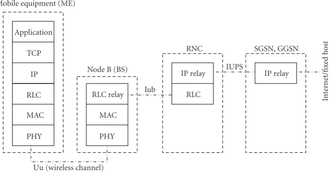
imple-ments packet fragmentation, selective repeat ARQ (with a bitmap acknowledged mode), and data concatenation. We added the SDU discard functionality in order to avoid infinite retransmission loops (as is often done in practical systems). An example of a typical UMTS architecture which can be simulated with the Miracle UMTS module is depicted inFigure 8.
4.3. Underwater Acoustic Communications. The
underwa-ter library deeply relies on the MPhy framework (see Section 3.2) to deal with multi-user interference, propaga-tion gain, channel delay, and noise power. The library comes in two flavors:
(1) a simplified version uses empirical equations for the calculation of delay, attenuation, and noise power.
These equations can be found in [25,26];
(2) a more powerful configuration called World Ocean
Simulation System (WOSS) [27]. Actual propagation
theories [28] aim to model channel power delay
or frequency attenuation profiles. WOSS is a multi-threaded framework that permits the integration into Miracle of any existing underwater channel simulator that expects environmental data as input and that provides as output a channel realization represented using the channel profiles just mentioned. Currently, WOSS integrates the Bellhop ray-tracing program
[29] while retaining the previous formula for the
noise power.
In both cases, the propagation effects are considered
con-stant over the duration of the packet. Specifically, Bellhop
calculations are performed across the whole bandwidth with custom resolution, while noise calculations are performed
at the geometric frequency (let f and fu be, respectively,
the lower and upper limits of the frequency band, then the
Mobile equipment (ME)
Application TCP
IP
RLC RLC relay RLC
RNC SGSN, GGSN
Figure8: Example architecture which can be simulated with the Miracle UMTS module. ME is the mobile user, Node B is the UMTS base station (BS), RLC is the radio link control (hosting ARQ algorithms), RNC is the Radio Network Controller (in charge of connection handling, handovers, QoS control, call admission control, etc.), SGSN and GGSN are, respectively, the serving and gateway GPRS support nodes.
of the propagation equations between a transmitter and a receiver, Bellhop requires the knowledge of the Sound Speed Profile (SSP), the Bathymetric Profile (BP), and the type of Bottom Sediments (BS), required to model acoustic power
losses from bottom reflections. TheSound Speed Profileis the
propagation speed of sound considered as a function of water
depth. Different profiles lead to potentially very different
propagation effects, including surface sound channels, deep
sound channels, convergence zones, shadow zones, and so
on; see [28]. In this respect, WOSS offers a technology
independent database API and a number of classes to manipulate SSP, BP, and BS data. For the SSP, we employ a
custom implementation of the World Ocean Database [31], a
collection of SSPs measured during a number of experiments all around the world; the measurements are divided by location and day or season of the year when the measurement
was performed (recall that sound propagation is affected
by water temperature, which in turn undergoes seasonal changes, especially in the superficial layer). The bathymetric data have been taken from the General Bathymetric Chart
of the Oceans [32], a public database offering samples of
the depth of the sea bottom with an angular spacing of 30 seconds of arc. Finally, the type of bottom sediments is provided by a reasoned geo-acoustic analysis of the National
Geophysical Data Center’s Deck41 data-base [33]. The effort
of interfacing all components pays off, in that the user only
has to specify the location in the world and the time where the simulation should take place. This is done by setting the simulated date and the wanted latitude and longitude of every node involved. The simulator automatically handles the rest. In more detail, the simulator picks the location (i.e., latitude, longitude, and depth) of the transmitter and the receiver and queries the database manager for samples of bottom sediments, measured SSPs (for simplicity, the SSP can also be assumed to be constant, on average, throughout the network area) and for bathymetric data along the path. Full customization of “surficial”, bathymetric and SSP data
is also possible if more accurate data is available (with the term “surficial” we refer to the surface of the sea bottom, as opposed to superficial, which usually refers to the water surface). The power delay profile obtained with Bellhop can be used to schedule the reception of replicas of the packet: in detail the user can choose to coherently combine the complex channel gains with a custom resolution time window and obtain one or more complex channel taps.
In Figures 9 and 10, we show the coherent sum of all
channel taps, obtained with WOSS for an example scenario. Figure 9represents the attenuation incurred by an acoustic wave at 4 kHz transmitted in August, approximately 20 km
offshore the harbor of Taranto, Italy, with the transmitter
located at 40.32◦N, 17.12◦E. Darker shades of gray represent
stronger signal power. The figure shows that the signal reaches the surface near the harbor (top right corner, about
11 km from the transmitter) bearing sufficient power to allow
correct reception. By contrast, Figure 10 shows the same
scenario in March: in this case, the average temperature of the water is lower, changing the way the sound is refracted and reflected by the sea bottom. Here, any acoustic receiver deployed between 9 and 11 km from the transmitter may be unable to acquire the transmitted signal. Furthermore, a shadow zone of about 2 km appears in front of the transmitter, causing failure in a hypothetical short range communication scenario.
4.4. WiMAX. WiMAX [34, 35] is a standard defined by
IEEE802.16 task group for wireless broadband access net-works, designed to provide high-speed wireless access. Sev-eral extensions of ns2 providing WiMAX support have been proposed in the last few years; one of the most popular is that
implemented by the NIST laboratories [36]. This work has
been subsequently adapted to Miracle by the DISCO group
of the University of Karlstad [37]; this version provides more
5
Figure9: Attenuation incurred by acoustic waves at 4 kHz trans-mitted in August approximately 20 km offshore Taranto harbor, 40.32◦N, 17.12◦E. A darker shade of grey represents a stronger signal. Surficial sediments are a mixture of sand and clay; a sharply increasing sea bottom profile can be seen in the lower half of the picture.
Orthogonal Frequency Division Multiplexing (OFDM) sys-tem, together with additional functionalities such as network entry, flow management, scheduling and mobility extension. In order to extend this WiMAX module for Miracle, several enhancements have been developed during the Democles
project [38] resulting in a new library called WiMAX for
Democles (WiDe) [39], as we discuss in the following.
First of all, our work focused on providing a more accurate model of the PHY layer. Previously, the WiMAX Miracle module relied on a simple disk propagation model, where the packet reception behavior was determined by simply comparing the received power with a predetermined threshold, equal for all transmission schemes. This
assump-tion is too simplistic, since the different modulation and
coding schemes which can be used in WiMAX offer a
range of different tradeoffs between transmission speed and
reliability. Moreover, the physical transmission of OFDM
systems such as WiMAX is affected by complex propagation
phenomena due to the time and frequency selective nature of
the channel. What happens is that the different subcarriers
(from 256 up to 2048 in WiMAX) in which the available bandwidth is subdivided may experience frequency selective
fading, in which case they are affected by different channel
gains. In order to address these aspects, we introduced
the possibility of simulating the effect of propagation (i.e.,
path loss, shadowing, and fading components) for each of the subcarriers. This allows the calculation of signal-to-interference plus noise ratios (SINR) for each channel, which are ultimately used to compute packet error probabilities
(PER). The mapping SINRs → PERs is done through
curves obtained off-line using a link level simulator. These
curves were mapped using the Mutual Information Effective
SINR Mapping technique (MIESM) [40], according to the
methodology described in [41]. We adopted this approach
to extend the OFDM module of the NIST code and to design a new PHY layer module supporting the Orthogonal
5
Figure 10: Attenuation incurred by acoustic waves at 4 kHz transmitted in March approximately 20 km offshore Taranto harbor, 40.32◦N, 17.12◦E. A darker shade of grey represents a stronger signal. The figure refers to the same geographical area of Figure 9.
Frequency Division Multiple Access (OFDMA) technology, which is adopted by mobile WiMAX. The implemented subchannelization scheme is the Partial Usage of the Sub-Channels (PUSC) where the 1024 subcarriers are mapped to 30 logical nonadjacent channels so as to improve the independence of the channel response across subcarriers.
From a data link layer perspective, we added support for Automatic Repeat reQuest (ARQ) and for the relay
architec-ture detailed in the IEEE802.16j [42] standard. The latter is
an extension to WiMAX systems according to which Relay Stations (RS) are deployed in order to expand the coverage and possibly improve the throughput of the WiMAX access network. In this extension of the Miracle WiMAX module, we considered the case of nontransparent RSs, which implies that relay nodes are in charge of generating their own MAC signaling and of autonomously managing the connection with both base stations and mobile terminals.
Finally, WiDe supports the simulation of the WiMAX network reference model defined by the WiMAX Forum
[43]. This model is composed by three main components: the
mobile station (MS), the network access provider (NAP), and the network service provider (NSP). The MS corresponds to the subscriber station (SS) in the IEEE standard nomen-clature. The NAP is composed by the set of entities that are needed to provide and manage a link layer connection with the SSs, therefore it can be composed of a single base station (BS) or a set of them. The NSP is the entity in charge of managing the incoming connectivity requests and negotiating the service requirements. A sketch of a possible
architecture is given inFigure 11.
5. Projects Using Miracle
VIDEO CODEC (e.g., FFmpeg)
RTP (real time protocol)
IP SS WiMAX MAC SS WiMAX PHY
CSN
(connectivity service network)
BS WiMAX MAC BS WiMAX PHY
BS WiMAX MAC BS WiMAX PHY SS
R2
R3
R4
· · ·
NAP
R1
BS1 BSN
MS NSP
Figure11: Example architecture which can be simulated with the WiDe module. Mobile station is what has been called subscriber station (SS) from IEEE standard nomenclature, the network access provider (NAP) is composed by the set of functionalities to manage a connection from radio point of view with the SSs (therefore can be a single BS or a set of them) and the network service provider (NSP) is the entity in charge of managing the incoming requests of connectivity and negotiating the service requirements.
(i) The Ambient Networks Phase2 project [44] targeted
transparent wireless access and services in a multi-technology environment. One of its main objectives was to provide support for multi-technology termi-nals, that is, to allow users to seamlessly migrate
between different technologies and networks and,
in addition, to dynamically manage the business relations with their access providers. Many research activities have been carried out using Miracle in order to test the proposed architecture.
(ii) The ARAGORN project [45] explores key enabling
technologies that facilitate the application of machine intelligence and adaptive communications technolo-gies in the optimization of resource usage in wireless networks. Part of the research activity carried out within ARAGORN is being performed using Miracle.
(iii) NURC [46] is one of three research and technology
organizations of NATO. It conducts world class maritime research in support of NATO’s operational and transformation requirements. The Centre has the ability to conduct maritime and undersea research from concept formulation to validation at sea with its exceptional combination of expertise and steady
rotation of staff from and to the Nations. Mission
evaluation, network analysis, and protocol dimen-sioning for underwater acoustic communications systems will be done using Miracle.
(iv) The Democles project [38] is an internal project
carried out at CTTC with the aim of developing a framework for simulating next generation wireless networks. As part of the most recent activity within this project, Miracle has been integrated with the pre-existing simulation framework, and is being actively used for several research activities.
We would like to note that many researchers have used and are using Miracle in their work, as is proved from the amount
of interactions seen on thensmiracle-usersmailing list.
Furthermore, many research publications have been reported to use Miracle for their performance evaluation; a complete list would be very long and is therefore omitted.
6. Conclusions
In this paper, we presented the Miracle framework, dis-cussing its architecture, its features, and the wireless technol-ogy models it provides. We are confident that the features of Miracle, in particular its multi-interface and cross-layer capabilities, together with the possibility of simulating
several different wireless technologies, make it a very effective
tool for the simulation of 4G networks and beyond. Further-more, the fact that Miracle is open-source, its community-based development model, and the modularity of its code base and its APIs make it a very good tool for research institutions and universities.
As a final note, we would like to point out that Miracle is still being actively developed, and therefore there are several interesting opportunities for future research and development activity, among which we would like to mention validation studies for the models currently included in Miracle, as well as the development of modules for the simulation of emerging wireless technologies such as LTE and Cognitive Radio.
Acknowledgments
The work at the Centre Tecnol `ogic de Telecomunications de Catalunya was partially supported by the Catalan Regional Government under grant 2009SGR-940 and by the Democles
(R) project [38]. The work at the Department of Engineering
through the ARAGORN project [45] (FP7 ICT-216856) as part of the Seventh Framework Programme ICT-2007.1.1 “The Network of the Future.” This article is dedicated to the memory of Federico Maguolo, one of the original designers and developers of Miracle, who died in a tragic accident in June 2008.
References
[1] S. Shakkottai, T. S. Rappaport, and P. C. Karlsson, “Cross-layer design for wireless networks,” IEEE Communications Magazine, vol. 41, no. 10, pp. 74–80, 2003.
[2] I. F. Akyildiz and X. Wang, “Cross-layer design in wireless mesh networks,”IEEE Transactions on Vehicular Technology, vol. 57, no. 2, pp. 1061–1076, 2008.
[3] R. W. Thomas, D. H. Friend, L. A. Dasilva, and A. B. Macken-zie, “Cognitive networks: adaptation and learning to achieve end-to-end performance objectives,” IEEE Communications Magazine, vol. 44, no. 12, pp. 51–57, 2006.
[4] S. Haykin, “Cognitive radio: brain-empowered wireless com-munications,”IEEE Journal on Selected Areas in Communica-tions, vol. 23, no. 2, pp. 201–220, 2005.
[5] D. D. Clark, C. Partridge, J. Ramming, and J. T. Wroclawski, “A knowledge plane for the internet,” in Proceedings of the Annual Conference on the ACM Special Interest Group on Data Communication (SIGCOMM ’03), Karlsruhe, Germany, August 2003.
[6] N. Baldo, F. Maguolo, M. Miozzo, M. Rossi, and M. Zorzi, “ns2-MIRACLE: a modular framework for multi-technology and cross-layer support in network simulator 2,” in Proceed-ings of the ACM International Workshop on Network Simulation Tools (NSTools ’07), Nantes, France, October 2007.
[7] “The Enhanced Network Simulator,” http://www.cse.iitk .ac.in/users/braman/tens.
[8] “Hyacinth: An IEEE802.11-based Multi-channel Wireless Mesh Network,”http://www.ecsl.cs.sunysb.edu/multichannel. [9] R. Ag¨uero and J. P´erez, “Adding Multiple Interface Support in
NS-2,”http://personales.unican.es/aguerocr.
[10] L. Paquereau and B. E. Helvik, “A module-based wireless node for ns-2,” inProceedings of the ACM International Workshop on NS-2: The IP Network Simulator (WNS2 ’06), Pisa, Italy, October 2006.
[11] T. R. Henderson, S. Roy, S. Floyd, and G. F. Riley, “ns-3 project goals,” inProceedings of the ACM International Workshop on NS-2: The IP Network Simulator (WNS2 ’06), Pisa, Italy, October 2006.
[12] S. Varatharajan, A. Jabbar, A. Mohammad, et al., “Cross-Layer Framework for the ns-2 Simulator,” The University of Kansas, June 2008.
[13] B. Liang and Z. J. Haas, “Predictive distance-based mobility management for PCS networks,” inProceedings of the Confer-ence on Computer Communications (INFOCOM ’99), vol. 3, pp. 1377–1384, New York, NY, USA, March 1999.
[14] “MIRACLE: Multi InteRfAce Cross Layer Extension for ns-2,”http://telecom.dei.unipd.it/download.
[15] “An improved 802.11 implementation for ns2 with enhanced interference model,”http://www.dei.unipd.it/wdyn/?sez alias =ricerca/signet/tools/dei80211mr.
[16] Q. Chen, F. Schmidt-Eisenlohr, D. Jiang, M. Torrent-Moreno, L. Delgrossi, and H. Hartenstein, “Overhaul of IEEE 802.11 modeling and simulation in ns-2,” inProceedings of the 10th
ACM Symposium on Modeling, Analysis, and Simulation of Wireless and Mobile Systems (MSWiM ’07), pp. 159–168, Chania, Greece, October 2007.
[17] L. Betancur, R. C. Hincapi´e, and R. Bustamante, “WiMAX channel: PHY model in network simulator 2,” inProceedings of the ACM International Workshop on NS-2: The IP Network Simulator (WNS2 ’06), Pisa, Italy, October 2006.
[18] A. F. Harris and M. Zorzi, “Modeling the underwater acoustic channel in ns2,” in Proceedings of the 2nd International Conference on Performance Evaluation Methodologies and Tools (NSTools ’07), Nantes, France, October 2007.
[19] I. Purushotaman and S. Roy, IEEE802.11 Implementation Issues in Network Simulator 2, Department of Electrical Engineering, University of Washington, Washington, DC, USA,http://ee.washington.edu/research/funlab.
[20] A. Mishra, V. Shrivastava, S. Banerjee, and W. Arbaugh, “Partially overlapped channels not considered harmful,” in Proceedings of the ACM International Conference on Mea-surement and Modeling of Computer Systems (SIGMET-RICS/Performance ’06), Saint-Malo, France, June 2006. [21] E. G. Villegas, E. L ´opez-Aguilera, R. Vidal, and J. Paradells,
“Effect of adjacent-channel interference in IEEE 802.11 WLANs,” inProceedings of the 2nd International Conference on Cognitive Radio Oriented Wireless Networks and Communica-tions (CrownCom ’07), pp. 118–125, Orlando, Fla, USA, July-August 2007.
[22] G. Perale,A study of the effect of the non-orthogonality of the channels in IEEE 802.11 systems, M.S. thesis, University of Padova, Padova, Italy, April 2009.
[23] “Enhanced UMTS Radio Network Extensions for ns-2,” http://eurane.ti-wmc.nl/eurane.
[24] M. Rossi, P. Casari, M. Levorato, and M. Zorzi, “Multicast streaming over 3G cellular networks through multi-channel transmissions: proposals and performance evaluation,” in Pro-ceedings of the IEEE Wireless Communications and Networking Conference (WCNC ’05), vol. 3, pp. 1761–1766, New Orleans, La, USA, March 2005.
[25] R. Urick, Principles of Underwater Sound, McGraw-Hill, Boston, Mass, USA, 1983.
[26] M. Stojanovic, “On the relationship between capacity and distance in an underwater acoustic communication channel,” ACM Mobile Computing and Communications Review, vol. 11, no. 4, pp. 34–43, 2007.
[27] F. Guerra, P. Casari, and M. Zorzi, “World ocean simulation system (WOSS): a simulation tool for underwater networks with realistic propagation modeling,” in Proceedings of the 4th ACM International Workshop on UnderWater Networks (WUWNet ’09), Berkeley, Calif, USA, November 2009. [28] F. Jensen, W. Kuperman, M. Porter, and H. Schmidt,
Compu-tational Ocean Acoustics, Springer, New York, NY, USA, 2000. [29] “Bellhop code,”http://oalib.hlsresearch.com/Rays/index.html. [30] P. C. Etter, Underwater Acoustic Modeling and Simulation,
Spon Press, Taylor & Francis, London, UK, 2003.
[31] “World ocean atlas,”http://www.nodc.noaa.gov/OC5/WOA05 /pr woa05.html.
[32] “General bathymetric chart of the oceans,”http://www.gebco .net/.
[33] “National geophysical data center, seafloor surficial sedi-ment descriptions,”http://www.ngdc.noaa.gov/mgg/geology/ deck41.html.
[35] IEEE Std. 802.16e-2005, “IEEE Standard for Local and Metropolitan Area Networks—Part 16: Air Interface for Fixed Broadband Wireless Access Systems—Amendment 2: Physical and Medium Access Control Layers for Combined Fixed and Mobile Operation in License Bands,” February 2006. [36] “The Network Simulator ns-2 NIST add-on—IEEE 802.16
model (MAC+PHY),” Tech. Rep., National Institute of Stan-dards and Technology, June 2007.
[37] “NS2MiracleWimax,” http://ns2miraclewimax.sourceforge .net.
[38] “DEMOCLES, Simulation-based testbed for dynamic RRM,” http://www.cttc.es/en/projects/testbeds/project/DEM-OCLES.jsp.
[39] “WiMAX for DEMOCLES,”http://www.cttc.cat/wiki/access/ index.php/Democles.
[40] K. Brueninghaus, D. Ast´elyt, T. Salzer, et al., “Link perfor-mance models for system level simulations of broadband radio access systems,” inProceedings of the IEEE International Symposium on Personal, Indoor and Mobile Radio Communi-cations (PIMRC ’05), vol. 4, pp. 2306–2311, Berlin, Germany, September 2005.
[41] WiMAX Forum, “WiMAX System Evaluation Methodology Doucument—Version 1.0,” January 2007.
[42] IEEE Std. 802.16j, “Air Interface for Fixed Broadband Wireless Access Systems: Multihop relay specifications,” July 2008. [43] WiMAX Forum White Paper, “Mobile WiMAX—part I: a
technical overview and performance evaluation,” March 2006. [44] N. Niebert, A. Schieder, J. Zander, and R. Hancock,Ambient
Networks, John Wiley & Sons, 2007.
[45] “The ARAGORN project,”http://www.ict-aragorn.eu/. [46] “The Nato Undersea Research Centre,”http://www.nurc.nato