Volume 2010, Article ID 476732,20pages doi:10.1155/2010/476732
Research Article
MIMO Network Coding-Based PHY/MAC Protocol for
Replacement of CSMA/CA in Efficient Two-Way Multihop
Relay Networks
Gia Khanh Tran, Kei Sakaguchi, and Kiyomichi Araki
Department of Electrical and Electronic Engineering, Tokyo Institute of Technology, Meguro-ku O-okayama 2-12-1, Tokyo 152-8552, Japan
Correspondence should be addressed to Gia Khanh Tran,[email protected] Received 2 January 2010; Revised 20 May 2010; Accepted 20 June 2010
Academic Editor: Meixia Tao
Copyright © 2010 Gia Khanh Tran et al. This is an open access article distributed under the Creative Commons Attribution License, which permits unrestricted use, distribution, and reproduction in any medium, provided the original work is properly cited.
Backbone wireless mesh networks have attracted much of attention due to their wide-range applications. The use of CSMA/CA based MAC protocols in mesh networks, however, leads to an inefficient resource utilization, and to high latency. Several alternative protocols including directional MAC, multichannel MAC only provide marginal improvement. Recently, a cross-layer design employing multiple antenna techniques and network coding called MIMO network coding was proposed. Owing to multiple access interference cancellation ability of MIMO, bi-directional flow multiplexing capability of network coding in combination with an efficient channel access scheme of TDMA/TDD, MIMO two-way relay provides significantly high end-to-end capacity. In this paper, MIMO network coding is considered as an alternative PHY/MAC protocol of CSMA/CA. This paper provides details of the protocol and develops network simulators for performance evaluation. Furthermore, an efficient retransmission scheme for transmission system employing network coding is proposed. The paper shows that MIMO network coding achieves significant network performance improvement with respect to CSMA/CA mesh networks. The proposed retransmission scheme is also shown to be effective in terms of resource usage as well as QoS guarantee.
1. Introduction
Wireless mesh networks (WMN) consisting of mesh routers and mesh clients have been achieving much attention in recent years as they allow innovative applications, namely wireless sensor networks, public wireless access networks, wireless plant control systems, and smart utility networks [1]. The advantages of a WMN are its ability to form a flexible network topology, its robustness and its wide area coverage owing to multihop relay property.
In the near future, the infrastructure/backbone WMN needs to improve its network capacity to support client applications which require to exchange data in larger amount and with a better quality. Figure 1 shows some examples of such applications, for example, public wireless access, home network, intervehicle network, and sensor network. For instance, public wireless access networks need to support
many users who request bandwidth for high data rate multimedia contents. Home networks should accommodate high-end consumer applications, such as those for data-intensive multimedia equipment having multiple channels of high-resolution digital video.
Public wireless access (a)
Home network (b)
Intervehicle network
(c)
Industrial sensor network
Sink node
Sensor node
Backbone network Sensor network
(d)
Figure1: Some applications of the future wireless mesh networks.
increasing largely the system cost, noting that the mesh nodes of infrastructure/backbone WMN are fixed and well power-supplied.
We return to the reason why conventional mesh networks are not satisfiable in terms of achieving high data rate and guarantee good QoS. In all shared medium networks, medium access control (MAC) is an important technique that enables the successful operation of the network. IEEE 802.11 MAC, which employs carrier sense multiple access with collision avoidance- (CSMA/CA-) based sensing and backoffprocedures, is considered as the standard MAC of many conventional wireless networks established by 802.11 working group [6], for example, WLAN. While simple to use and efficient for local one-hop transmission, 802.11 MAC does not scale to larger networks and presents a serious loss of performance in terms of delay, fairness and most critically, throughput [7, 8]. CSMA/CA is also not suited for the high rate contention and collision environment associated with wireless mesh networks. In such environ-ment, without careful design, the performance of CSMA/CA deteriorates due to various problems. For example, basic access of CSMA/CA suffers from hidden node problem, which increases the probability of packet collision. RTS/CTS can be introduced to avoid this problem at the expense of causing a new problem, which is the exposed node problem. This latter reduces the opportunities of concurrent transmissions in a network. Some other problems are deaf terminal, information asymmetry and flow-in-the-middle [9]. Moreover, CSMA/CA also has a large impact on end-to-end delay due to processing through the physical, MAC and
network layers, requeuing at the network and MAC layers, and recontention for channel access at every hop [10].
of MIMO as a PHY candidate for mesh network does not guarantee significant improvement. In other words, a cross-layer design is required.
On the other hand, network coding has emerged in recent years as a technology which can improve the capacity of a network with multiple information flows. This tech-nique, which is originally proposed for the network layer in [17] for improvement of multicast capacity, has been adopted into PHY, for example, analog network coding [18] in a classical two-way relay [19] topology, or digital network coding [20] in a one-way multihop relay topology. Both works theoretically showed an asymptotic throughput gain of two after the introduction of network coding. Experiments of network coding (from now on, the term “network coding” shown in this paper refers to network coding in PHY), for example, [21] (digital network coding) and [22] (analog network coding), in a nonsynchronized network with spe-cific topologies, that is, two-way relay topology, X topology, and ad hoc, also showed a MAC and coding gain ranging from 1.3 to 1.7. The combination of network coding with MIMO furthermore promises a higher achievable gain. For a two-way relay topology, [23] considered two approaches of message combining at the relay node: superposition coding and XOR precoding, and derived the optimal beamforming method to maximize the sum rate of two users exchanging packets through the relay node. Capacity region in the broadcast phase of MIMO two-way relay has been derived in [24], where this region is convex and contains achievable rate regions of [23]. In [25], MIMO two-way relay employing XOR precoding was extended to the case of multiuser MIMO where mobile stations exchange uplink/downlink packets with the base station through a common relay node. An iterative algorithm was also employed for sum rate maxi-mization. [26] furthermore extended network coding and MIMO for one dimensional (1D) two-way multihop relay topology. The algorithm, which is called as MIMO network coding (MIMO-NC), is a synchronized TDMA/TDD scheme where nodes are assumed to be synchronized to each other and transmissions are realized in time slot unit. [26] does not employ optimal beamforming since optimal beamforming for a MIMO two-way relay multihop network is still an open problem. Instead, [26] employs MMSE as a MIMO detector at any Rx, without any precoding at Tx. Thus, [26] does not require CSI at Tx and is practical for implementation in multihop networks. It had been shown that owing to multiple access interference cancellation ability of MIMO, bidirectional flow multiplexing ability of network coding in combination with an efficient channel access scheme of TDMA/TDD, MIMO-NC provides significantly high end-to-end capacity in comparison with conventional synchronized MAC protocols.
In this paper, MIMO-NC is reconsidered as an alternative cross-layer design PHY/MAC protocol with linear topogy (although a linear topology is considered in this paper, the algorithm of MIMO-NC can be extended to other topologies including cross topology [16], rotary topology [27], tree topology [28]. The combination of all these topologies makes MIMO-NC applicable to general topology of mesh network) mesh network and its performance is
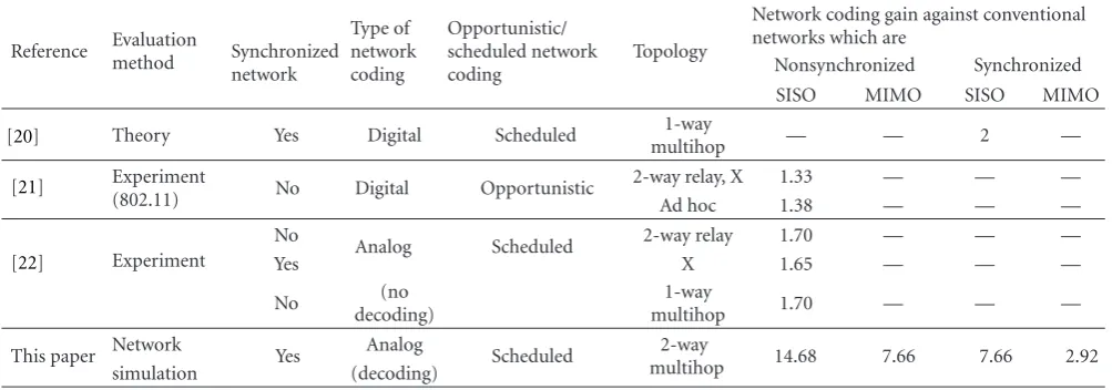
compared with conventional CSMA/CA, slotted CSMA/CA-based protocols and their corresponding extensions with MIMO. To consider MIMO-NC as a cross-layer PHY/MAC protocol, this paper defines transmission scheme, frame format, resource allocation, and retransmission scheme of the protocol. Two mesh network simulators, respectively, employing MIMO-NC- and CSMA/CA-based protocols are developed. Therefore, comparison is performed in terms of network performance. The results show that MIMO-NC achieves a significant improvement in network throughput (e.g., 14 times with respect to CSMA/CA (RTS/CTS), packet-delivery ratio as well as packet-delay reduction in com-parison with other (nonslotted/slotted) CSMA/CA-based mesh networks. For interested readers, Table 1 compares the achievable throughput gain owing to the introduction of network coding, which was reported in [20–22], with respect to that achieved in this paper. From the table, it can be seen that the significant improvements of MIMO-NC can be attained owing to a scheduled synchronized network (network synchronization and scheduling can be achieved using the approach, e.g., in [29]. Since we consider a mesh backbone network supporting high traffic, the cost for synchronization and scheduling is not a critical problem. The synchronization and scheduling are only performed in the initial phase of the backbone network. Therefore, we can ignore its effect on the total network throughput), the introduction of MIMO, and efficient bidirectional flow multiplexing capability of network coding.
In terms of implementation of network coding in real system, this paper moreover discusses about the design of network coding header and proposes an efficient retrans-mission scheme based on network coding header. Analysis is performed to show the efficiency of the proposed scheme. This retransmission scheme is furthermore implemented into the developed network simulator and simulation results confirm the benefit of the proposed scheme.
The rest of the paper is organized as follows. Sections
2 and 3, respectively, describe CSMA/CA protocols and MIMO-NC. Details about network simulator are provided in
Section 4.Section 5describes the design of network coding
header and the proposed retransmission scheme. Numerical results are presented in Section 6. Finally, the paper is concluded inSection 7.
2. Revisiting CSMA/CA
The 802.11 specification supports two different MAC schemes, the distributed coordination function (DCF) and the point coordination function. This paper concentrates on two methods used in DCF as follows.
2.1. CSMA/CA Basic Access Method. This method uses only DATA frames and ACK (acknowledgment) frames as shown
inFigure 2(a). The node which wants to send a data frame
Table1: Network coding gain in terms of throughput against conventional networks not employing network coding.
Reference Evaluation
method Synchronized network
Type of network coding
Opportunistic/ scheduled network coding
Topology
Network coding gain against conventional networks which are
Nonsynchronized Synchronized
SISO MIMO SISO MIMO
[20] Theory Yes Digital Scheduled 1-way
multihop — — 2 —
[21] Experiment
(802.11) No Digital Opportunistic
2-way relay, X 1.33 — — —
Ad hoc 1.38 — — —
[22] Experiment
No
Analog Scheduled 2-way relay 1.70 — — —
Yes X 1.65 — — —
No (no
decoding)
1-way
multihop 1.70 — — —
This paper Network Yes Analog Scheduled multihop2-way 14.68 7.66 7.66 2.92
simulation (decoding)
frame received. If the medium is busy, the transmitting node will wait until the end of the current transmission plus another DIFS, and then defers for a random backoff period before transmission. This paper employs the binary exponential backoff[6] where the backoffcounter follows a uniform distribution with its maximum value being doubled after every failed transmission until a maximum value CWmax, or being reset to an initial value CWmin after a
successful transmission. In this paper, (CWmin, CWmax) is
selected as (15,1024) in compliant with [6]. One big problem of this access method is the hidden terminal problem, which will be explained later.
2.2. CSMA/CA Protocol Using RTS/CTS. To avoid hidden terminal problem, it is proposed to use request-to-send (RTS) and clear-to-send (CTS) frames. This method is a four-phase RTS-CTS-DATA-ACK protocol as shown in
Figure 2(b). The node that wants to send a DATA frame
first senses the channel. If the channel remains idle for a DIFS interval, then it sends an RTS frame. Otherwise, it starts the backoff algorithm after waiting till the end of current transmission and a further DIFS period. When the destination receives the RTS, it transmits CTS after SIFS. The source node is then allowed to transmit DATA frame, after successful reception of the CTS frame. All other nodes which hear the RTS, CTS, or DATA frame update their NAV.
2.3. Associated Issues of CSMA/CA in 1D Mesh Network with Bidirectional Flows. In this section, we present several issues of CSMA/CA in a 1D mesh network with bidirectional flows. For instance, we consider a mesh network consisting of five nodes as shown inFigure 3with a forward flow from node no. 1 to node no. 5 and a backward flow from node no. 5 to node no. 1.
(1) Hidden terminal problem: a node is said to be hidden from the transmitter (Tx) if it can cause a collision at the receiver (Rx) by transmitting, but cannot hear any signal sent by the Tx. An example is given in
Figure 3(a). Node no. 3 is a hidden node of the Tx-Rx
pair no. 1 and no. 2 with the assumption that carrier sensing range is one hop.
(2) Exposed terminal problem: for a given Tx-Rx pair, an exposed terminal is a node which can perceive signals sent by the Tx, but cannot cause a collision at the Rx.
InFigure 3(b), node no. 2 is an exposed node for the
Tx-Rx pair no. 3 and no. 4.
(3) Deaf terminal problem: a deaf terminal is the one that is unable to interpret the handshake messages from a Tx-Rx pair in its neighborhood. InFigure 3(c), node no. 3 is not able to interpret the CTS from node no. 2 to node no. 1, if there is an on-going data transmission from node no. 4 to node no. 5. Once the transmission from node no. 4 to node no. 5 is completed, node no. 3 could send out an RTS and cause a collision at node no. 2. This problem occurs in any single flow; therefore it also happens in the case of bidirectional flows.
In a 1D mesh network with bidirectional flows, there is a combination of the aforementioned problems. Therefore, it can be predicted that the introduction of CSMA/CA in such networks will reduce the throughput and increase the latency extremely.
2.4. Alleviating Collision with Slotted CSMA/CA. To par-tially alleviate the probability of collision in CSMA/CA, slotted CSMA/CA has been proposed [13]. In this scheme, nodes are assumed to be synchronized with each other. Furthermore, contention for channel access as well as packet transmission must be completed in predefined time slot. This paper employs a slotted CSMA/CA scheme as depicted
in Figure 2(c). It is almost similar to the CSMA/CA using
DIFS: distributed coordination function (DCF) inter frame space
RTS: request to send CTS: clear to send
SIFS: short inter frame space NAV: network allocation vector
Source
Destination
Other Busy
DIFS
DATA SIFS
ACK
NAV
DIFS Backoff
(a) CSMA/CA with basic access method
Busy DIFS
RTS SIFS
CTS SIFS
DATA SIFS
ACK NAV (DATA) NAV (CTS) NAV (RTS)
DIFS Backoff
(b) CSMA/CA using RTS/CTS
Source
Destination
Other DIFS
RTS SIFS
CTS
DATA
SIFS ACK Defer to next slot
(b) slotted CSMA/CA using RTS/CTS
FixedTslot
FixedTcont<< Tdata FixedTdata
Fixed
TacK
ACK period DATA
transmission period Contention period
DIFS Backoff
Figure2: Two CSMA/CA algorithms.
acknowledge it by sending ACK packets during the ACK period. During the contention period, other nodes beside the source and the destination node have to defer from contending for channel until the next time slot. In this paper, contention window for slotted CSMA/CA is fixed as CWmin. It means that the backoff counter follows a
uniform distribution with maximum value of CWmin. For
a fair comparison with CSMA/CA and MIMO network coding, slotted CSMA/CA in this paper is designed based on parameters of IEEE 802.11. The scheme is slightly different from that in [13] in terms of backoff mechanism, frame duration, and so forth.
3. MIMO Network Coding
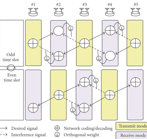
This section defines the transmission scheme and the resource allocation of MIMO-NC.Figure 4depicts an exam-ple of MIMO-NC applied to a linear topology with five equally placed nodes each equipped with two antennas. However, the scheme works for arbitrary number of nodes. The algorithm is efficient because only a single channel is required.
There are two flows of information, namely the forward
flow (F) which transports information from the leftmost to the rightmost node and the backward flow (B) which transports information in the reverse direction. Each node
is assumed to be employed withM =2 antennas. At a time slot, transmitters and receivers are located adjacently to each other, and nodes switch their functions of Tx or Rx at every time slot. Let HR,T ∈ C2×2 represent the channel matrix
between Tx node T and Rx node R. Also,WR
r ∈C2×2denotes
Rx weight at node R. Besides,nR∈C2represents the noise
vector with zero mean and covarianceσ2Iat node R.
This paper employs a decode, spool and forward relaying mechanism. Let assume a flow runs through a set of nodesΩ = {(1),. . .,(k),. . .,(K)}. For instance,ΩF =
{1,. . .,k,. . .,K}andΩB = {K,. . .,k,. . ., 1}in this paper.
Letc(k)(n) denote native packets of flowto be relayed at
a node(k) at timen. Passingc(k)(n) through an encoder
and modulator results in a corresponding modulated signal
s(k)(n). This process is expressed ass(k)(n)=F(c(k)(n)),
where F(since this paper employs adaptive modulation and coding per flow, this operator is associated with the subscripts(k)(n) which is also the subscript of the operand c(k)(n). Without losing generality, the subscript is omitted
for sake of expedience) is an operator representing adaptive modulation and coding. Inversely, c(k)(n) can also be
written as c(k)(n) = F−1(s(k)(n)), where F−1 is an
(a) a hidden terminal problem (node #3)
(b) an exposed terminal problem (node #3)
(c) a deaf terminal problem (node #3)
Unable to transmit even the transmission
does not interfere with the others Unable to listen to a control message Idle Tx
Figure3: Associated issues of CSMA/CA in 1D mesh network with bidirectional flows. (Transmission range is assumed to be the distance between any two adjacent nodes in this figure).
time slot n, a part of the stored packets of each flow is adaptively selected for relaying based on the link condition. This operation of selection is defined asS-operator in this paper. For example,c(k)(n) is selected as packets of flowto
be relayed. Since packets of that flow are relayed from(k−1) to(k) up to time slotn−1,(k−1) has a perfect knowledge of c(k)(n). This fact can be symbolically represented as c(k)(n) ∈ νn=0−1c(k−1)(ν), where stands for the union
operator of sets. Thus, we define ˘c(k−1)(n−1) c(k)(n)
the replica ofc(k)(n) at(k−1). Applying theF-operator
on both sides of the previous formula and exchanging the left side with the right side, the following equality is achieved
s(k)(n)=s˘(k−1)(n−1), (1)
where ˘s(k−1)(n−1) F( ˘c(k−1)(n−1)) represents the
replica ofs(k)(n) at(k−1). This equality is called as the
law of flow conservation in this paper.
3.1. In Odd Time Slotn=2p−1,p∈N+. In this time slot,
odd number nodes are Tx node and even number nodes are Rx node. Transmit signalsskt
FBof Tx nodekt=2q+ 1,q∈N
where a simple analog network coding is employed. This manipulation results in 3 dB power loss in both forward and backward direction.
At a Tx node T, transmit signal is mapped to one of the antenna by the following Tx weightwT
t =[1 0]T. The
Since nodekrhas two antennas (due to the multiple access of
#1 #2 #3 #4 #5
Transmit mode Receive mode Odd
time slot
Network coding/decoding Orthogonal weight Desired signal
Interference signal Even
time slot
Figure4: MIMO network coding (MIMO-NC).
nodes, and spatial multiplexing of network coding streams [16]), the desired signals can be retrieved by using MIMO linear detection algorithm as follows:
skr=
skr−1
FB s kr+1
FB T
=Wkr
r H
ykr.
(5)
Here, for an MMSE decoder
Wkr
r =
Hkr
Hkr
H
+σ
2
PI −1
Hkr, (6)
where P is the Tx power. It should be noticed that the interference from distant nodes (overreach interference) are taken into account in this paper, however the MMSE decoder at each Rx does not deal with this interference.
Based on network decoding and the law of flow conser-vation,skr−1
F (n),skBr+1(n) can be estimated as follows:
skr−1
F (n)=
√
2skr−1
FB −˘s kr
B(n−1),
skr+1
B (n)=
√
2skr+1
FB −s˘ kr
F(n−1).
(7)
Estimated signals are demodulated, decoded and stored in the buffer of node kr as F−1(skFr−1(n)), F−1(skBr+1(n)).
In the final step, after checking the destination address of the buffered packets, nodekr adaptively selects packets for
relaying and performs modulation and coding. For example, from the buffer of the forward flow nν=0F−1(skr−1
F (ν)),
packets which have not been relayed to node kr + 1 are
adaptively selected as ckr
F(n+ 1) S( n
ν=0F−1(skFr−1(ν))).
Thus, the modulated signal of the forward flow becomes
skr
F(n+ 1)F(c kr
F(n+ 1)).
3.2. In Even Time Slotn+ 1=2p,p∈N+. In the (n+ 1)th
time slot, odd number nodes become Rx node and even number nodes become Tx node. The discussion is the same as innth time slot by switching the role ofktandkrsuch that kt=2q,q∈N+andkr=2q+ 1,q∈N.
The repetition of processes in odd and even time slots results in a single channel MIMO-NC. Frame format, relay mechanism and retransmission scheme of MIMO-NC are provided in later sections.
4. MIMO-NC as a PHY/MAC Protocol and
Architecture of Network Simulator
To compare the network performance of MIMO-NC with CSMA/CA based MAC protocols, network simulators have been developed. This section explains the details about the packet relaying schemes used in these simulators. Therefore, information about frame format, packet relaying mechanism of MIMO-NC are studied in this section. Basically, we consider packet relaying of bidirectional flows using con-ventional method of CSMA/CA (Basic Access or RTS/CTS) and its enhancement usingM×MMIMO (M =2), slotted CSMA/CA with RTS/CTS and its enhancement with 2×2 MIMO, and the proposed MIMO network coding.
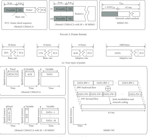
4.1. Frame Format, Packet Format and Resource Mapping.
The frame format of the relaying schemes is presented in
Figure 5.Figure 6(b) shows how these frames are mapped
16 us 4 us
Preamble SIG Packet FCS Basic rate
FCS : frame check sequence (Slotted) CSMA/CA
16 us 4 us #1 Preamble SIG
Packet(s) #M Preamble SIG
(Slotted) CSMA/CA withM×MMIMO
Tslot
Figure5: Frame format.
RTS FCS
Basic rate
20 bytes 14 bytes
CTS FCS (a) Four types of packet
Spatial
(Slotted) CSMA/CA withM×MMIMO
DATA-BW-1 DATA-BW-2 BW: backward flow
DATA-BW-J
DATA-FW-1 DATA-FW-2 DATA-FW-3 DATA-FW-I
FW: forward flow Joint modulation and network coding
(b) Resource mapping of packets
Figure6: Resouce mapping of different types of packet used in network simulators.
with fixed sizes are considered in this paper as shown
in Figure 6(a). The control packets of RTS and CTS are
modulated using basic rateRb. Based on channel condition,
DATA and ACK are adaptively modulated with adaptive rate
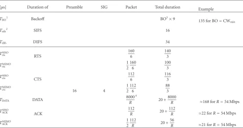
R, therefore the frame durations of DATA and ACK are variable. At the end of a packet, a frame check sequence (FCS) is attached for the purpose of detecting packet error at receiver nodes. Important time durations of CSMA/CA including backoff duration, interframe spaces which are defined in [6], and packet durations which are calculated based on data rate and packet size, are summarized in
Table 2.
For a fair comparison, slotted CSMA/CA is introduced at the expense of synchronization among nodes. Frame format of slotted CSMA/CA is the same as that of CSMA/CA except
that channel contention and packet transmission is only allowed to occur in predefined time slots. Configuration of a time slot of slotted CSMA/CA is presented in Table 4. The duration of data transmission period is fixed as that of MIMO-NC (Tdata=4/3 ms). During this period, depending
Table2: Important time duration of (nonslotted/slotted) CSMA/CA (unit:μs).
[μs] Duration of Preamble SIG Packet Total duration Example
TBO1 Backoff BO3×9 135 for BO=CW
min
Tsifs2 SIFS 16
Tdifs DIFS 34
TSISO
rts RTS
160 6
140 3
TMIMO rts
1 2
160 6
100 3
TSISO
cts CTS
112 6
116 3
TMIMO
cts 16 4
1 2
112 6
88 3
TDATA DATA
8000
R
4
20 +8000
R 168 forR=54 Mbps
TSISO
ACK ACK
112
R 20 +
112
R 22 forR=54 Mbps TMIMO
ACK
1 2
112
R 20 +
56
R 21 forR=54 Mbps
1T•
UPPERCASEmeans that the duration is variable, depending on the number of backoffcounter (TBO) or adaptive modulation scheme (others). 2T•
lowercasemeans that the duration is a fixed value. 3A (random) backoffcounter.
4R[Mbps] is the data rate which depends on adaptive modulation scheme.
of RTS/CTS. In terms of the time parameters, there are two main differences between slotted CSMA/CA with respect to CSMA/CA. First, in CSMA/CA, for each transmission of a data packet, a phase of channel contention is required. In contrast, multiple data packets can be transmitted in a same time slot after a single contention for channel access in slotted CSMA/CA. Second, since channel contention is only allowed in the fixed contention period, the (wasteful) portion of time which is not used for data transmission in slotted CSMA/CA case is deterministic and is small compared to data transmission period. On the other hand, that of CSMA/CA is a random variable and may become large as the contention window is doubled after each data packet transmission failure. Similarly to the case of CSMA/CA, spatial multiplexing MIMO is also extended for slotted CSMA/CA.
In the case of MIMO-NC, PHY resource before network coding is virtually extended to spatial domain with one forward stream and one backward stream as shown in
Figure 6(b). One PHY frame contains a preamble, a signal
field, an extended network coding header and ends with a DATA frame consisting of multiple network coded DATA packets. The duration of the DATA frame is fixed to 4/3 ms to ensure that at least one packet per flow can be relayed when basic rate Rb is selected. Different from the case of
conventional CSMA/CA, PHY frame of MIMO-NC may contain multiple DATA packets per stream, according to the algorithm of rate adaptation based on channel condition. For instance, when the data rate of 54Mbps is chosen,
maximally 9 DATA packets per stream can be transmitted simultaneously. The configuration of a time slot of MIMO-NC is summarized in Table 4. The number of packet of each flow that can be relayed during the period of 4/3 ms with respect to adaptive modulation scheme is shown in
Table 3. PHY header of a frame of MIMO-NC contains a
preamble, used for channel estimation, and also a network coding header. The role of the network coding header will be explained in later sections. Furthermore, since MIMO-NC is a TDMA/TDD-based protocol, the handshake using RTS/CTS is not adopted.
In MIMO-NC, each node is equipped with multiple antennas (M = 2). For a fair comparison, we extend CSMA/CA with MIMO. This extension is based on IEEE 802.11n [30] with modification of antenna configuration to M × M. Since PHY resource is extended to spa-tial domain, mapping of packets to PHY resource block
(Figure 6(b)) is changed such that control packets (RTS/CTS
and ACK) is mapped across all spatial resources, while different DATA packets are mapped to different spatial streams. This mapping helps to reduce inefficient trans-mission duration of control packets and multiplex multiple DATA packets at the same time to achieve higher data rate.
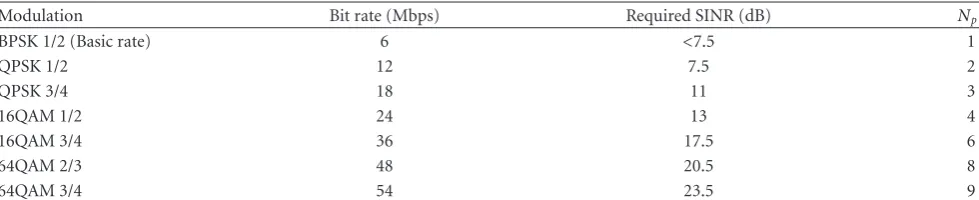
Table3: Adaptive modulation table for required PER=10−2.
Modulation Bit rate (Mbps) Required SINR (dB) Np1
BPSK 1/2 (Basic rate) 6 <7.5 1
QPSK 1/2 12 7.5 2
QPSK 3/4 18 11 3
16QAM 1/2 24 13 4
16QAM 3/4 36 17.5 6
64QAM 2/3 48 20.5 8
64QAM 3/4 54 23.5 9
1The maximum number of packets per flow in slotted CSMA/CA and MIMO-NC.
Table4: Time slot configuration of slotted CSMA/CA and MIMO-NC (unit:μs).
[μs] Contention period (Tcont) Data transmission ACK transmission Total
Tdifs TBO Trts Tsifs Tcts Tsifs Tdata Tsifs ×TACK Tslot
Slotted CSMA/CA Tdifs+ 9CWmin+T SISO
rts +TctsSISO+ 2Tsifs TackS−SISO 5023
3
TcontS−SISO= 859
3
164 3 Slotted CSMA/CA
with 2×2 MIMO
Tdifs+ 9CWmin+TrtsMIMO+TctsMIMO+ 2Tsifs 4000
3 T
S−MIMO
ack 4927
3
TS−MIMO cont =
791 3
136 3
[μs] PHY header DATA transmission ACK transmission Total
Preamble SIG Network coding header
MIMO-NC 16 4 Thdr=
2LNbit
Rb =33
1 4000
3 0
2 4159
3 1N
bitdenotes the number of required bits to represent sequence number of packets andRbis the basic rate of 6 Mbps.
2MIMO-NC does not require ACK packets since the mechanism of acknowledgment and retransmission is embedded in network coding header.
corresponds to the address of the Rx node (MyAddr), the packet is passed to the mesh layer. Otherwise, the Rx node sets its NAV according to the duration field of the packet. At the mesh layer, if the final destination address field of the packet does not match MyAddr, Rx node looks up its routing table for the address of the next hop node, then puts the packet back to the Tx buffer for relaying. A scheduler always checks the availability of PHY layer and selects packet(s) to be mapped to resource blocks of the PHY layer for transmission. In the case of conventional CSMA/CA with single antenna, scheduling algorithm is a first-in-first-out (FIFO) type. However, for efficient usage of spatial resource in enhanced CSMA/CA with MIMO, we propose a scheduler which selects M packets intended to a same next hop neighbor to pass to PHY layer. If there is not enough packets jointly satisfying the scheduler’s rule, the scheduler will wait for another chance. The same process is extended to slotted CSMA/CA and slotted CSMA/CA with MIMO. During data transmission period, a scheduler continuously moves packets (via a same destination) from MAC layer to available PHY resources, which depends on channel condition at each time slot.
As shown in Figure 7(b), packet-relaying process of MIMO network coding is simple. Since there are always two
kinds of packets, that is, the forward packets from forward stream and backward packets from backward stream, an Rx node has two different buffers containing corresponding packets. At the time period when the Rx node becomes a Tx node, a scheduler will select the first I packets from the forward buffer andJ packets from the backward buffer to map to the corresponding resource block of PHY. The number of I and J is decided based on a per stream rate adaptation algorithm taking into account the channel conditions.
5. Efficient Retransmission Scheme for
MIMO Network Coding
Despite the potential of network coding, it seems far from seeing wide-spread deployment across real WMN networks. One of the possible reasons for this is that it lacks of an efficient network-coding-oriented retransmission scheme.
NAV setting
My packet
Routing table Receive correct data packet(s)
Nexthop Addr resource slots of PHY
Frame transmission
Conventional 2×2 MIMO
Select P1 (1 packet) Select P1, P3 (2 packets) (a) (Slotted) CSMA/CA and (Slotted) CSMA/CA with 2×2-MIMO.
Final Dest. Addr
= MyAddr?
Final Dest. Addr
Fi l D Add
of PHY based on AMC
My packet Yes
Receive correct data packet(s) of backward flow
Receive correct data packet(s) of forward flow
Final Dest. Addr =MyAddr?
Put packet to Tx buffer
of forward flow to map to forward flowSelectsIfirst packet(s) of PHY based on AMC
Rx beamforming
Replica for network decoding of backward flow
Retransmission
Retransmission
Transmit time?
(b) MIMO-NC
Figure7: Packet relaying mechanism.
flow but also give rise to errors in other flows due to the natural property of network coding.
Despite its importance, to our best knowledge, there are very little work on packet retransmission for WMN employing network coding. The retransmission scheme in COPE [21] is based on the transmission of acknowledgment packet (ACK) at every hop of the relay network. The source node continues to retransmit the network coded packet until it receives ACKs from all of the desired destination nodes. In this algorithm, a destination node only sends back an ACK if it succeeds in receiving and in (network) decoding the received network coded packet. In [31], besides ACKs, transmissions of negative acknowledgment packet (NACK) is introduced to improve the delay performance. In this scheme, when a node does not have enough native packets required for successful network decoding of a received network coded packet, it sends out a NACK to request for the missing native packets.
The above algorithms ensure the reliability of WMN at the expense of resource utilisation for transmission of control
packets (ACK/NACK). Furthermore, the algorithms are more inefficient, knowing that control packets are required at every hop of the relay network for end-to-end delivery of any single packet. In this section, we propose an efficient retrans-mission scheme in which transretrans-missions of control packets are not required. Instead of using ACK/NAK packets, we propose a suitable manipulation of the packet header of network coded packets to fully convey acknowledgment information. The proposed scheme also exploits the multihop relaying property.
5.1. Network Coding Header Design. The format of a network coded frame containing multiple packets is presented in
Figure 8. Since link adaptation is employed in
iF
X(1) iFX(2) iXF(3) iFX(I) iBX(1)iBX(2) iBX(3) iBX(J)
iBX(1) iBX(2) iBX(I)
iFX(1) iFX(2) iFX(3) iFX(J)
0 0 0 0
Lslots forward flow
Lslots backward flow
PHY headers
Ts Packet number of
I-th packet of forward flow No packet
Network coded signals
Ts=4/3 ms
DATA 1000 bytes
FCS Adaptive rate
Forward flow Backward flow
. . . . . .
. . . . . .
. . . . . .
. . .
. . .
Figure8: Network coding header.
Tconv R−A+TR−Bconv
Tconv AB−R
A R B
Td
Ta
(a) Conventional scheme (1 antenna at relay)
Tconv2 R−AB
Tconv2 AB−R
A R B
Td
Ta
(b) Conventional scheme (2 antennas at relay)
Figure9: Conventional retransmission schemes.
flow are combined in an order and modulated separately. The modulated signals of two flows are then added to form the network coded signals. Each packet of each flow is assigned with a unique sequence number. To facilitate the
network decoding, sequence number of packets are stored in network coding header in the same order of packets. Network coding header is divided into two parts which contains the sequence numbers of the forward flow and the backward flow packets, respectively. Each part is divided intoLslots. Each slot has a size of Nbit, which is the number of bits
required to represent the sequence number of packet. Nbit
is related to the buffer size. A mechanism how to assign sequence number of packet effectively to reduceNbit is out
of scope of this paper. For the calculation of the duration of network coding header,Nbit =11 bits is roughly selected
in this paper. Besides, L, which equals 9 in this paper, is a system design parameter representing the maximum number of packets of a flow to be relayed in one PHY frame. It depends on the highest supported data rate. If only I packets are selected to be relayed, the other L−I
slots are filled with zeros. Like the signal field (SIG) in PHY frame of 802.11, network coding header, which contains critical information, must be sent through a very reliable link. In this paper, the basic rate is used for transmission of the header.
5.2. Efficient Retransmission Scheme for Two-Way Relay Using Network Coding Header. For ease of exposition, we first consider a model of three nodes where R is the relay node of both A and B as shown inFigure 9.
LetTdandTarepresent the frame durations of a packet
and of an ACK frame respectively. Let us assume that for any data transmission, a packet is delivered with an equal packet error rate pe. We also assume that an ACK frame is always
received correctly. In the 1st phase, the average time required for successful transmission of a packet from A (B) to R is given as follows:
correctly received at thenth attempt. In the 2nd phase, the probabity that R finishes its transmission at thenth attempt can be calculated as
p(n)
= (1 −pe)2p2en−2
Both A and B fail to receive the packet at all attempts except in thenth attempt
+ 2
Treat A and B equally
× (1 −pe)pne−1
A fails to receive the packet at all attempts except in thenth attempt
× 1−pn−1
e
B has succeeded in receiving the packet before thenth attempt
,
(9)
where the first term represents the probability that both A and B successfully receive the packet from R at thenattempts for the first time. The second term represents the probability that one of the two receivers successfully receives packet from R at thenth attempt for the first time while the other node has already successfully received the packet in previous attempts. The average time required for this broadcast phase is given by
Finally, the average spectral efficiency of the conventional scheme can be calculated as
ρconv= ρTd
where ρ[bps/Hz] is the spectral efficiency of modulation scheme used to transmit a packet andα=Ta/Td.
For a fair comparison, in the conventional retransmission scheme, it is also assumed that node R is equipped with two antennas as shown inFigure 9(b). Hence, A and B can transmit packets to R simultaneously and R can send two ACKs to A and B concurrently using MIMO broadcast. In the first phase of multiple access, retransmission is repeated until R successfully receives packets both from A and B. The average time required to complete the second phase of broadcast can be calculated following the same reasoning, leading to the below spectral efficiency
Tconv2
AB−RandTR−ABconv2 represent the average time required
for successful transmission in the broadcast and the multiple access phases respectively. By the way, this paper uses a same average packet error rate pe of the broadcast phase (SISO)
and the multiple access phases (2×2 MIMO) since, based on discussion in [32], the average SINR per stream of a full multiplexing MIMO system with MMSE receiver in Rayleigh fading channel is almost the same as the average SNR of the corresponding SISO channel.
5.2.2. Proposed Retransmission Scheme. In this section, we propose a retransmission scheme making use of network coding header as a negative acknowledgment (NACK) of lost packets. No explicit acknowledgment packet is required but such information are piggybacked in the network coding header of the transmit packet in the consecutive time slot. This approach is somewhat similar to the piggybacked scheme in [33]. However, [33] does not consider network coding and multihop relay. The proposed algorithm is explained using an example inFigure 10. In the first time slot, R receives packetiA from A. In the second time slot,
packetiBsent from B to R is lost. R may send a NACK to B to
announce the packet loss and wait for the retransmission of
iBfrom B. However, this approach is still inefficient. Since R
owns packetiA, it can relayiAto B while informing B of the
packet loss. In the third time slot, R sends only the forward packetiA. In the network coding header of R, the forward
is sent, the backward slot is filled with a special predefined index #. In this case, # is a sign of packet loss of backward packet which R could not receive in the previous time slot. When B receives the signal sent from R, it achieves packet
iA. Furthermore, since it discovers the sign # in the backward
slot of the header of R, it realizes that the backward packet
iBwhich B sent to R in previous time slot is not successfully
received at R. In the next transmission chance (time slot 3), B retransmitsiB.
The efficiency of the proposed scheme is compared to conventional schemes. Using the same discussion of previous part, the average time required for a packet to arrive at R is given by TR−Aprop = TR−Bprop = Td/(1−pe). Here, it should
be noticed that the time required for transmission of ACK becomes zero. In the broadcast phase, owing to the proposed algorithm, packets of two flows can be treated independently. The required time for a packet of the forward (backward) flow to be sent from R to B (A) is similarlyTA−Rprop=TB−Rprop =
5.2.3. Analytic Results. Without loss of generality, we assume
ρ = 1. Following packet format of 802.11a, the ratio of durations of ACK and data frame is set toα = 14/1000 =
0.014.Figure 11depicts spectral efficiency of the proposed
retransmission scheme with respect to different values of
pein comparison with conventional schemes. In this figure,
the bold lines represents theoretical results using (11), (12), and (13) and marks denote the simulation results. In the simulation, 3000 packets are generated from both ends, and are relayed to the other end. Packets are transmitted through channel with a packet error rate pe. The figure shows that
the analytical results agree with the simulation results. Also, the proposed retransmission scheme achieves the highest spectral efficiency at all area ofpe.
5.2.4. Application to MIMO-NC. In MIMO-NC, a frame contains multiple packets. Retransmission using ACK is extremely inefficient. If multiple ACKs are used for acknowl-edgment of each packet, a large part of the system bandwidth is used for transmission of ACK. If only one ACK is sent as acknowledgment for successful reception of a frame, one packet loss requires retransmission of the whole frame. However, the proposed algorithm can be easily extended for MIMO-NC.
Namely, # is used to inform a packet loss. At certain time slotn, a Rx node receives multiple packets of forward and backward flow whose packet sequence numbers are correspondingly stored in the network coding header of the received frame. For each packet, if it passes the FCS check, it is considered as a successfully received packet. Otherwise, the packet is considered as lost. In the next time slot n+ 1, the node becomes a Tx node and generates a network coding header. First of all, it puts # to the header slots which correspond to header slots of the lost packets in time slot
n. For instance, in time slot n, node R fails to receive a forward packet (sent from node T) whose sequence number
ωis stored in header slotlof the former part of the received network coding header. In time slotn+1, node R becomes Tx and node T becomes Rx. Node R generates a network coding header such that the header slotlof the former part is filled with #. The remaining header slots are available to insert sequence numbers of native packets encoded in network coded packets to be relayed. When a Rx node detects #s in the former (latter) L header slots from its next-hop node of forward (backward) flow, it recognizes a packet loss and schedules the retransmission of the corresponding forward (backward) packets. In the above example, since node T detects # in header slotlof the former part of its received network coding header, and it knows that sequence number
ω had been stored in this slot in time slotn, node T can acknowledge about the transmission failure of the forward packet with sequence numberωin the previous time slot and arrange a retransmission of the packet.
For further understanding of the algorithm, an example is given in Figure 12 with L = 3. In the first time slot, forward packets with sequence number 1 and 2 are sent from A and backward packets 1, 2, and 3 are sent from E. Since link adaptation is employed, the number of packets of each flow being relayed is smaller thanL. At the Rx side, B fails to receive packet 2 of the forward flow and D fails to receive packet 1 of the backward flow. In the second time slot, B and D become Tx node. B puts a # to the second slot of its header part containing sequence numbers of forward packets. Similarly, D puts a # to the first slot of its header part containing sequence numbers of backward packets. It is noticed that in this example, even if D owns packet 3 of the backward flow, it cannot immediately relay the packet because the adaptive modulation scheme at D at this time slot only allows D to relay one packet. When A receives the header of B, it acknowledges that the packet 2 of the forward flow fails to arrive at B and schedules its retransmission in the third time slot. Packet retransmission at the link E-D is performed in the same manner.
6. Network Performance Analysis
6.1. Simulation Setup and Parameters. In our simulations, five nodes are arranged in a line with equal distance as shown
inFigure 3. With this arrangement, average SNR per antenna
of any link connecting two adjacent nodes is assumed to beγ = 30 dB. No obstacles are assumed in the simulation environment and the path loss exponent is set to 3.5. This value is commonly used in factory environment where mesh networks are often deployed. Noise power has a typical value of −94 dBm. Carrier sensing level is −62 dBm [6], thus sensing range is almost within a distance of one hop. The channel is supposed to be quasistatic Rayleigh fading such that channel value does not change during the transmission of one frame. The channel reciprocity is also assumed, that is,
HR,T =HT,RT.M=1 in the case of conventional CSMA/CA
A R B a time slot
iB
iB
iA
iA
iA
iA
iA
iA 0 # 0
iB
0
iB
iB
#
iB
iB
iB
iB
0
iA
0
iA
#
iA
NAK detection
Retransmission
Retransmission
iA
i,A NAK
Network coding header Packet loss
Figure10: Proposed retransmission scheme for two-way relay (L=1).
0.1 0.15 0.2 0.25 0.3 0.35 0.4 0.45 0.5
10−6 10−4 10−2 100
Spect
ral
e
ffi
ciency
(bps/Hz/flo
w)
Packet error ratepe
Theory Simulation
Simulation Simulation
Prop
Conv2
Conv
Figure11: Analysis result of the proposed retransmission scheme for two-way relay. (Bold lines: theoretical results, Markers: simula-tion results).
the whole duration of the four phase handshake. In enhanced CSMA/CA with MIMO, a Rx node uses minimum mean square error (MMSE) detection method for separation of spatial schemes. Genie-aided rate adaptation for CSMA/CA and for MIMO-NC (per stream) are performed based on estimated signal-to-interference and noise ratio (SINR) and modulation table given inTable 3. In the simulators, there is no real transmission of preambles and headers. Perfect frame synchronization, perfect channel estimation, and no header errors are assumed. In CSMA/CA and slotted CSMA/CA based protocols, a Rx node detects a frame if it is currently idle and its received signal strength is larger than the Rx sensitivity. In MIMO-NC, perfect synchronization among
nodes are assumed. For all simulations, all far interference signals caused by simultaneous transmissions are taken into account and are captured in the SINR. The SINR might vary during the reception of a frame due to the nature of random access. For such cases, the minimum observed SINR is selected as the SINR of the frame. Packet error rate (PER) is calculated from SINR of a received frame by a method in [34]. Again, based on the probability given by PER, for each received packet, the Rx tosses an unequal coin to decide a successful or failed packet transmission. It is noted that in MIMO-NC, there is always interference from three nodes away from a Rx node. Dealing with header error in MIMO-NC is considered as our future work. Other system parameters are summarized inTable 5.
In the simulation setup, to make full utilization of MIMO-NC, packets of two flows of information (forward and backward) are generated from two end nodes following a Poisson distribution. The final destination of forward packets and backward packets are node no. 5 and node no. 1, respectively. Buffers at network layer of each node can store up to 300 packets per flow. For each flow, if the buffer is full, newly generated/received packets will be discarded. In contrast, a sent packet will be kept in a temporary buffer for retransmission until its ACK (or virtual ACK in case of MIMO-NC) is received, or retransmission reaches maximum attempt of 7. The paper does not consider the delay constraint of packets. Network simulators are run to observe the status of packets during a total period of one second. At the end, we calculate the network throughput by counting the total number of aggregated arrival packets divided by the observation time. Based on time log of arrival packets, the average packet delay is also found.
6.2. Network Performance
6.2.1. Adaptive Modulation and Coding. Figures 13 and
Time slot
1
2
3 4
A B C D E
Buffer of forward flow
Buffer of backward flow
Newly generated
1 2 0 0 0 0
1
0 0 0 0 0 0 3
2 0 0 0 1 2 3
2 1 # 0 0 0 0 1 2 0 0 0 # 2 0 1
2 3 4 0 0 0 43
2 2 0 0 0 2 0 0 1 31 0 0 0 1 4 0
4 Packet 2 of
backward flow arrive
2 3 4 2 0 0
2 33 1 4 4
1 0 0 3 1 4
Packet 1 of forward flow
arrive
Figure12: An example of the proposed retransmission scheme for MIMO network coding withL=3.
Table5: Physical channel parameters.
Bandwidth 16 MHz
Guard interval 1
4symbol
Average SNR per linkγ 30 dB
Noise power −94 dBm
Receiver sensitivity −82 dBm
Carrier sensing level −62 dBm
Fading channel Block Rayleigh fading
Pathloss exponent 3.5
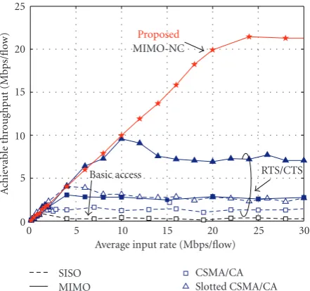
respectively. In Figure 13, it is interesting to look at the curves of random access-based protocols. In low-input rate area, the curve linearly increases with respect to input rate to a peak point, then gradually decreases to an output saturation level. The linearly increasing area indicates that input packets are successfully delivered to their destinations. But with a higher offered load, the channel congestion occurs and impedes the successful packet relaying at every links. Finally, the output rate saturation level exists due to the limited buffer size at the mesh layer of the implemented network simulator. In MIMO-NC, no congestion period exists, thus there is no hump in the throughput performance curve. At an input rate lower than (1 Mbps/flow), all schemes do not show any saturation. It means that all schemes including CSMA/CA based protocols can be used in light traffic environment. However, at a high-input rate where new packets are continuously generated at two ends of the network, Figure 13 reveals superior performance of MIMO-NC compared to all other CSMA/CA-based pro-tocols. While network throughputs of other protocols are saturated at low throughput value with respect to the offered load, that of MIMO-NC only saturates when offered load reaches 21 Mbps/flow. The saturated level of MIMO-NC is 21 Mbps/flow, much higher than 0.2 Mbps/flow (basic access), 1.5 Mbps/flow (RTS/CTS), 2.7 Mbps/flow (RTS/CTS with MIMO and slotted RTS/CTS), 7 Mbps/Hz (slotted RTS/CTS 2×2-MIMO). The saturation of MIMO-NC can be explained by 3 dB power loss of network coding and overreach interference, noting that the upper bound data rate
of this network is 1/2×54 [Mbps] = 27 [Mbps]. To better see the performance of nonslotted/slotted CSMA/CA-based protocols, the throughput and delay performance in low input rate area are zoomed in and shown in Figures14and
16, respectively. Basic access performs worst as a result of the hidden node problem at high input rate and saturates at the input rate of 1 Mbps/flow. Since CSMA/CA with RTS/CTS can alleviate hidden node problem, its achievable throughput is better than basic access with input saturation level is 1.5 Mbps/flow. When MIMO is introduced to RTS/CTS, the benefits of spatial multiplexing almost double the saturation point of RTS/CTS. Furthermore, paying for the cost of synchronization, we can observe large improvement of slot-ted CSMA/CA (and with MIMO). Since transmissions are restricted in predefined time slots, the probability of packet collision can be reduced thus improve achievable through-put. We can see the performance of slotted CSMA/CA is almost the same as that of CSMA/CA with MIMO, and slotted CSMA/CA with MIMO furthermore shows a significant gain with input saturation point of 10Mbps/flow. Here, we can conclude that scheduled schemes which require synchronization among nodes in mesh network can have drastically better performance than that of random access protocols. The significant gain of MIMO-NC with respect to other schemes can be achieved in the favor of bandwidth saving owing to efficient two-way relay and simultaneous transmission at different links in the network. For these reasons, performance of MIMO-NC should at least double the performance of slotted CSMA/CA with 2×2 MIMO. Simulation result, however, shows larger improvement more than the factor of 2 since the control packets of slotted CSMA/CA can still collide, and the PHY header of MIMO-NC is much smaller (thus more efficient) than collision period of slotted CSMA/CA.
In terms of packet delay, MIMO-NC also shows better performance than the others as shown inFigure 15. Delay performance curves raise up at the saturation input point. The result seen from this graph agrees well with the result
in Figure 13 that CSMA/CA saturates first, followed by
0
Average input rate (Mbps/flow) SISO
Figure13: Throughput performance comparison of CSMA/CA and MIMO network coding.
the low input rate area up to 10 Mbps/flow as shown in
Figure 16. In this area, MIMO-NC is below its saturation
point. Therefore, the generated packets are immediately relayed through four hops to its destination, which results in a delay of (Tslot×(Nnode−1) 6 ms). However, other
CSMA/CA-based protocols have worse performance except for basic access and RTS/CTS in input rate area lower than 1 Mbps/flow. In this area, since the channel is not congested and adaptive modulation is employed, a newly generated packet can be relayed per hop in shorter period than a time slot of MIMO-NC. By the same reason, since in slotted CSMA/CA scheme, packets are fixed in a time slot of duration longer than that of MIMO-NC, its delay performance is worse than that of MIMO-NC even in low input rate area. The delay performance of nonslotted and slotted CSMA/CA-based protocols with MIMO have the same characteristics, namely, very high at low input rate, lower in medium rate and raises again after saturation point. This phenomenon occurs due to packet relaying mechanism employed in this paper where the packets are only relayed if more thanM = 2 packets destined toward a same next hop exist in the MAC buffers of the relay. This mecha-nism is applied to exploit spatial multiplexing benefit of MIMO.
In summary, in heavy traffic area, scheduled MAC schemes, especially MIMO network coding, are not only superior than other schemes in terms of achievable through-put but also in terms of packet delay performance. In light traffic area of bursty source where the network is not congested, scheduled MAC schemes have comparable performance with CSMA/CA-based protocols in terms of throughput and provide a fixed packet delay (fixed QoS). However, random access like CSMA/CA-based protocols might have better delay performance than scheduled schemes employing slotted configuration of PHY frame.
0
Average input rate (Mbps/flow) Proposed
Figure14: Throughput performance comparison of CSMA/CA and MIMO network coding (light traffic).
0
Average input rate (Mbps/flow) Proposed
Figure 15: Average packet delay performance comparison of CSMA/CA and MIMO network coding.
When a link adaptation is employed without the pro-posed retransmission scheme, the number of lost packets at physical layer is reduced significantly. However, for some applications which do not allow packet loss, the proposed retransmission scheme is needed. It achieves zero packet loss as shown inFigure 17.
0
Average input rate (Mbps/flow)
Slotted CSMA/CA with MIMO RTS/CTS
Figure 16: Average packet delay performance comparison of CSMA/CA and MIMO network coding (light traffic).
0
Offered load (Mbps/flow) With retransmission
Without retransmission
Figure17: Number of lost packets per second at PHY observed in 4 s with link adaptation.
packets generated. Since high order modulation scheme is used at each transmission with the existence of intraroute interference, there is high probability of occurrence of packet loss. As seen in the figure, without retransmission, maximally only 25% of packets can be delivered successfully. However, when retransmission scheme is introduced, at low offered load, 100% of packets arrive at destination nodes. At higher offered load, packet loss occurs due to the buffer overflow.
7. Summary and Extension
The application of well-known CSMA/CA-based MAC protocols to mesh network reveals high latency and low resource utilization. Several alternative protocols only pro-vided marginal improvement. In recent publication, a cross-layer design employing multiple antenna techniques called
0
Offered load (Mbps/flow) With retransmission
Without retransmission
Fixed rate @ 54 Mbps
Figure18: Packet delivery ratio MIMO-NC network at fixed data rate of 54 Mbps.
MIMO-NC has been proposed for one dimensional mesh network. The technique was shown to provide significantly high end-to-end capacity. This paper considered MIMO-NC as an alternative PHY/MAC protocol of CSMA/CA and provided details on the design of the protocol, for example, packet format, relaying mechanism. This paper furthermore proposed an efficient retransmission scheme employing network coding header. The proposed retrans-mission scheme was shown to be effective in terms of resource usage as well as QoS guarantee. Simulation results from our developed network simulators also showed that MIMO-NC achieved an extremely large gain in terms of network throughput (14 times) and a significant reduction of packet latency in comparison with CSMA/CA mesh networks. Such improvements can be attained as the benefits of the scheduled synchronized network, the introduction of MIMO, and the efficient bidirectional flow multiplexing capability of network coding.
The network simulator and the proposed retransmission scheme presented in this paper can be easily extended to other network topologies, for example, 2D topology including “X-topology”, “Y-topology,” and cross topology [16], rotary [27] topology, tree topology [28], and so forth. Furthermore, owing to freedom of antenna at the Tx, space time block code (STBC) [26] can be introduced to improve link robustness. For future work, we consider the performance evaluation of MIMO-NC based on experiment using our developed MIMO mesh hardware [35] at 950 MHz band.
References
[1] I. F. Akyildiz and X. Wang, “A survey on wireless mesh networks,”IEEE Communications Magazine, vol. 43, no. 9, pp. S23–S30, 2005.
[2] E. Telatar, “Capacity of multi-antenna Gaussian channels,”
[3] G. J. Foschini, “Layered space-time architecture for wireless communication in a fading environment when using multi-element antennas,”Bell Labs Technical Journal, vol. 1, no. 2, pp. 41–59, 1996.
[4] H. B¨olcskei, D. Gesbert, and A. J. Paulraj, “On the capacity of OFDM-based spatial multiplexing systems,”IEEE Transactions on Communications, vol. 50, no. 2, pp. 225–234, 2002. [5] Q. H. Spencer, A. L. Swindlehurst, and M. Haardt,
“Zero-forcing methods for downlink spatial multiplexing in mul-tiuser MIMO channels,”IEEE Transactions on Signal Process-ing, vol. 52, no. 2, pp. 461–471, 2004.
[6] http://standards.ieee.org/getieee802/802.11.html.
[7] Z. Fu, P. Zerfos, H. Luo, S. Lu, L. Zhang, and M. Gerla, “The impact of multihop wireless channel on TCP throughput and loss,” inProceedings of the 22nd Annual Joint Conference on the IEEE Computer and Communications Societies (INFOCOM ’03), pp. 1744–1753, San Francisco, Calif, USA, April 2003. [8] S. Xu and T. Saadawi, “Revealing the problems with 802.11
medium access control protocol in multi-hop wireless ad hoc networks,”Computer Networks, vol. 38, no. 4, pp. 531–548, 2002.
[9] M. Garetto, T. Salonidis, and E. W. Knightly, “Modeling per-flow throughput and capturing starvation in CSMA multi-hop wireless networks,” IEEE/ACM Transactions on Networking, vol. 16, no. 4, pp. 864–877, 2008.
[10] R. Ramanathan, “Challenges: a radically new architecture for next generation mobile ad hoc networks,” inProceedings of the 11th Annual International Conference on Mobile Computing and Networking (MobiCom ’05), pp. 132–139, Cologne, Ger-many, September 2005.
[11] W.-T. Chen, M.-S. Pan, and J.-J. Dai, “An adaptive MAC protocol for wireless ad hoc networks using smart antenna system,” inProceedings of the 58th IEEE Vehicular Technology Conference (VTC ’03), pp. 2794–2798, October 2003. [12] R. R. Choudhury, X. Yang, R. Ramanathan, and N. H. Vaidya,
“On designing MAC protocols for wireless networks using directional antennas,”IEEE Transactions on Mobile Computing, vol. 5, no. 5, pp. 477–491, 2006.
[13] IEEE 802.15., “Part 15.4: Wireless medium access control (MAC) and physical layer (PHY) specifications for low-rate wireless personal area networks (WPANs),” Standard 802.15.4 R2006, ANSI/IEEE, 2006.
[14] B. Raman and K. Chebrolu, “Design and evaluation of a new MAC protocol for long-distance 802.11 mesh networks,” in
Proceedings of the 11th Annual International Conference on Mobile Computing and Networking (MobiCom ’05), pp. 156– 169, Cologne, Germany, September 2005.
[15] A. Nasipuri, J. Zhuang, and S. R. Das, “A multi-channel CSMA MAC protocol for multi-hop wireless networks,” in Proceed-ings of the IEEE Wireless Communications and Networking Conference (WCNC ’99), vol. 1, pp. 1402–1406, September 1999.
[16] G. K. Tran, K. Sakaguchi, F. Ono, and K. Araki, “2D MIMO network coding with inter-route interference cancellation,”
IEICE Transactions on Communications, vol. 92, no. 12, pp. 3665–3675, 2009.
[17] R. Ahlswede, N. Cai, S.-Y. R. Li, and R. W. Yeung, “Network information flow,”IEEE Transactions on Information Theory, vol. 46, no. 4, pp. 1204–1216, 2000.
[18] P. Popovski and H. Yomo, “Physical network coding in two-way wireless relay channels,” inProceedings of the IEEE International Conference on Communications (ICC ’07), pp. 707–712, Glasgow, Scotland, June 2007.
[19] C. E. Shannon, “Two-way communication channels,” in
Proceedings of the 4th Berkeley Symposium on Mathematical Statistics and Probability, vol. 1, pp. 611–644, 1961.
[20] Y. Wu, P. A. Chou, and S. Y. Kung, “Information exchange in wireless networks with network coding and physical-layer broadcast,” inProceedings of the 39th Annual Conference on Information Sciences and Systems, March 2005.
[21] S. Katti, H. Rahul, W. Hu, D. Katabi, M. M´edard, and J. Crowcroft, “XORs in the air: practical wireless network coding,” in Proceedings of the ACM SIGCOMM Conference on Applications, Technologies, Architectures, and Protocols for Computer Communication, vol. 36, pp. 243–254, Pisa, Italy, October 2006.
[22] S. Katti, S. Gollakota, and D. Katabi, “Embracing wireless interference: analog network coding,” in Proceedings of the ACM SIGCOMM Conference on conference on Applications, Technologies, Architectures, and Protocols for Computer Com-munications, pp. 397–408, Kyoto, Japan, August 2007. [23] I. Hammerstr¨om, M. Kuhn, C. Es¸li, J. Zhao, A. Wittneben, and
G. Bauch, “MIMO two-way relaying with transmit CSI at the relay,” inProceedings of the 8th IEEE Signal Processing Advances in Wireless Communications (SPAWC ’07), June 2007. [24] R. F. Wyrembelski, T. J. Oechtering, I. Bjelakovi´c, C. Schnurr,
and H. Boche, “Capacity of Gaussian MIMO bidirectional broadcast channels,” inProceedings of the IEEE International Symposium on Information Theory (ISIT ’08), pp. 584–588, July 2008.
[25] C. Es¸li and A. Wittneben, “Multiuser MIMO two-way relaying for cellular communications,” inProceedings of the 19th IEEE International Symposium on Personal, Indoor and Mobile Radio Communications (PIMRC ’08), September 2008.
[26] F. Ono and K. Sakaguchi, “MIMO spatial spectrum sharing for high efficiency mesh network,” IEICE Transactions on Communications, vol. 91, no. 1, pp. 62–69, 2008.
[27] G. K. Tran, K. Sakaguchi, F. Ono, and K. Araki, “Network capacity improvement with two dimensional MIMO network coding,” inProceedings of the 2nd International Conference on Signal Processing and Communication Systems (ICSPCS ’08), December 2008.
[28] G. K. Tran, K. Sakaguchi, F. Ono, and K. Araki, “Y-type MIMO network coding with cooperative null beamforming,” IEICE Technical Report vol. 108, no. 445, RCS2008-257, March 2009. [29] K. Mizutani, K. Sakaguchi, and K. Araki, “Network syn-chronization for two-way multi-hop relay networks with block modulation,” inProceedings of the 71st IEEE Vehicular Technology Conference Fall (VTC ’10), May 2010.
[30] IEEE 802.11 WG. IEEE P802.11n/D3.01 Draft Amendment to Standard for Information Technology—Telecommunications and Information Exchange Between Systems—Local and Metropolitan Networks—Specific Requirements—Part 11: Wireless LAN Medium Access Control (MAC) and Phys-ical Layer (PHY) Specifications: Enhancements for Higher Throughput. November 2007.
[31] H. Hiramuki, H. Okada, and K. Mase, “Performance com-parison of ARQ schemes for network coding in ad hoc networks,” inProceedings of the 19th IEEE International Sym-posium on Personal, Indoor and Mobile Radio Communications (PIMRC ’08), pp. 1–5, September 2008.
[33] D. P. Bertsekas, R. Gallager, and T. Nemetz,Data Networks, Prentice Hall, Englewood Cliffs, NJ, USA, 1987.
[34] G. K. Tran, N. D. Dao, K. Sakaguchi et al., “Performance analysis of MIMO schemes in residential home environ-ment via wideband MIMO propagation measureenviron-ment,”IEICE Transactions on Fundamentals of Electronics, Communications and Computer Sciences, vol. 93, no. 4, pp. 814–829, 2010. [35] K. Mizutani, T. Miyamoto, T. Kanno, K. Araki, and K.