R E S E A R C H
Open Access
IMS-based distributed multimedia
conferencing services for next-generation
mobile networks
Tien Anh Le
1*, Hang Nguyen
2*and Noel Crespi
2Abstract
Distributed architecture offers many advantages compared to centralized architecture in terms of providing
multimedia services. However, as a trade-off, distributed architecture requires that peers contribute a portion of their bandwidth and computational capacity to maintain the mutual overlay interconnection. This requirement develops into a serious problem for mobile users and wireless infrastructure, as the radio resource in this network is
tremendously expensive, based on 3gpp (2005), and is one of the reasons why distributed architecture has not been widely applied in next-generation (4G) networks. It is also the main reason why multimedia services such as video conference have to rely on a costly centralized architecture built over an expensive media resource function controllers via the Internet protocol (IP) multimedia subsystem (IMS). This research work proposes a new distributed architecture utilizing intelligence and extra capacity, currently available on LTE and WiMAX base stations to reduce the required bit rates that each peer has to provide in order to maintain the overlay network. This reduction saves
valuable radio resources and allows a distributed architecture to provide video conferencing services on 4G networks, with all the advantages of a distributed architecture such as flexibility, scalability, smaller delay, and lower cost. In addition, this can be implemented with a minimum modification of the standardized IMS platform and the 4G infrastructure, thereby saving the operators and service providers from excessive investments. A prototype has been built to prove the feasibility of the proposed architecture and evaluate its performances. The results show that our proposed distributed video conferencing service can actually reduce the average bandwidth required for data and signaling messages at wireless mobile terminals while maintaining the main operations of a video conference session.
Keywords: Distributed video conference; Service architecture; Distributed architecture; Overlay network; P2P; IMS; LTE; WiMAX; NGN; ALM; 4G
1 Introduction
Video conferencing service is the most complex type of multimedia communication. There are two main types of video conferencing service architectures: centralized architecture using multipoint control units (MCU) and distributed architecture using a multicast mechanism. Centralized architecture has many disadvantages, such as cost (incapable of decreasing the capital expenditures or of lowering operational expenditure, moreover, the radio resource in wireless network is tremendously expensive [1]) or a very high level of delay - especially when the
*Correspondence: [email protected]; [email protected] 1Samsung Vietnam Mobile Center, Samsung Electronics VietNam - Viet Nam 2Institut Mines-Telecom, Telecom SudParis, 9 rue Charles Fourier, Evry 91011, France
number of participants increases, the lack of flexibility and scalability, and a single point of failure.
More specifically, when more participants want to join a video conference (e.g., at big events), the cost of a centralized architecture increases sharply. Therefore, dis-tributed architectures are foreseen to be the future of video communication service. Skype, a peer-to-peer (P2P) VoIP client developed by KaZaa in 2003, has so far the most popular Internet-based video conferencing service. This application is able to throttle its sending rate to match the unpredictable Internet bandwidth while pre-serving resources [2]. Like its file-sharing predecessor KaZaa, Skype is an overlay peer-to-peer network. There are two types of nodes in this overlay network, ordinary
hosts and super nodes. An ordinary host is a Skype appli-cation that can be used to place voice calls and send text messages. A super node is an ordinary host on the Skype network [3]. Its main limitation is that the ‘super node’ architecture requires an infrastructure, similar to a con-tent delivery network, to be built and maintained in order to provide the video conferencing service. Moreover, as a commercial production, all its architectures and pro-tocols are closed source which leads to many difficulties for the research community in their attempts to improve Skype’s performance. Spiers and Ventura [4] implemented Internet protocol (IP) multimedia subsystem (IMS)-based video conference systems with two different architec-tures, server-client and P2P, and measured their signal-ing and data traffic overhead. Their results showed that server-client offers better network control together with a reduction in signaling and media overhead, whereas P2P allows flexibility but at the expense of higher overhead. Another system, Nefsis, provides dedicated cloud com-puting resources for video conferencing. Users automat-ically connect to geographautomat-ically close servers distributed on the Internet to have a low-latency experience [5].
The MCU centralized architectures act as a single-point recipient for each participant, thus requiring a large bandwidth connection just only for itself. It prepares a multipoint video representation that can fit into a smaller bandwidth and sends it to each participant. However, because of the complexity and cost of the operating of the MCUs, they are mostly used by large business appli-cations that can afford such equipment. They also suffer from single point of failures and hence are not failure transparent. A distributed architecture needs no special hardware or network infrastructure. Its P2P architec-ture prevents single point of failures and provides failure transparency. There is no additional networking and com-puting resources needed at the end points other than that of a point-to-point video conference [6]. In terms of delay performance and required computational capac-ity, distributed architecture outperforms its centralized counterpart as shown in [7]. The quality of video content transmitted over the specifically designed overlay network has also been proved to be better than that of the cen-tralized architecture, using objective quality evaluation methods [8].
One of the main reasons why distributed architecture has not been widely applied in the wireless networks is that it increases the required bit rates at mobile termi-nals and within the network. Indeed, in mobile wire-less networks, bandwidth is a very costly and limited resource. Therefore, it is almost impossible (for users) to apply directly the basic distributed architecture in mobile networks (due to the extra requirements in bit rates, mobile terminals’ battery life, computation, and the wire-less resources for maintaining the overlay structure). To
date, the mobile network and services have only been based on a centralized architecture. Almost no work has been found for distributed video conferencing service on mobile networks.
Recently, mobile participants have been equipped with high computational devices using radio access net-works (e.g., fourth generation (4G) long-term evolution, WiMAX), bigger screen sizes, and better computational capacity. Real-time multimedia services (such as video conference, video streaming) are foreseen to be ‘killer’ applications on 4G. It is expensive and difficult to provide such services based on a centralized architecture. How-ever, the distributed video conferencing service architec-ture and the 4G network architecarchitec-ture have been designed separately without considering the other’s requirements. Therefore, it is currently also difficult to provide real-time multimedia services based on a distributed architecture over 4G networks.
4G networks rely on the IMS [9] to provide multime-dia services including video conferencing. In turn, the IMS-based video conferencing service is built and stan-dardized for MCU-based or centralized service architec-ture. Therefore, it shares many similar problems with the centralized video conferencing service architecture [8], especially when the number of user equipment (UE) units that participate in the conference via the 4G infrastructure increases.
This research work proposes a solution for a dis-tributed architecture that allows the reduction of bit rates required by peers to save their valuable radio resources and make the distributed architecture possi-ble for next-generation mobile networks. In this research work, the long-term evolution-worldwide interoperability for microwave access (LTE-WiMAX) network is used as a demonstration of a 4G infrastructure. The main differ-ence between the proposal and the conventional methods is that it can apply the distributed service architecture on next-generation wireless network without modifying too much of its standardized architecture. That is the rea-son why in the prototype’s scenarios, we concentrated mainly on how the new proposal can perform better on 4G WiMAX networks rather than only compare between the centralized and distributed architectures.
at the wireless terminals. In our solution, we will try to overcome this main disadvantage of the distributed archi-tecture, which is why we will evaluate the performance of our proposal in terms of bit rates for data and signaling plans.
A new solution is proposed here, which makes it pos-sible for the current IMS-based LTE-WiMAX infrastruc-ture to seamlessly support distributed video conferencing services. The main contributions of the research are the following:
• Propose an IMS-based architecture that supports LTE-WiMAX’s UEs and WiMAX’s SU to participate in distributed scalable video conferencing service without using a centralized MCU. It significantly reduces the bit rates required at mobile terminals, thus conserving the wireless resources
• Develop a proof of concept prototype to prove the feasibility and compatibility of the newly proposed solution
• Evaluate the performance of the proposed system under audio and video conference working scenarios
Our proposed architecture’s requirements call for the following:
• New session initiation protocol (SIP) messages and some standard ones with modifications for new functionalities, new purposes, and in new contexts in their destinations and content
• A minimum modification of the 4G’s base station (BS)
• New xAS features
The rest of the paper is organized as follows. In Section 2, the 3rd Generation Partnership Project (3Gpp)’s standard for IMS-based video conferencing ser-vice will be introduced. Section 3 introduces our proposal for the IMS-based distributed video conference service and shows how it enables a distributed service archi-tecture to be utilized over wireless networks without increasing the radio resource requirements.
In Section 4, a prototype is constructed and the perfor-mance results are evaluated. We present our conclusions in Section 5.
2 3GPP IMS-based conference architecture
Figure 1 shows the 3Gpp standard architecture for the IMS-based conference architecture. Here, SIP and real-time transfer protocol (RTP) are used as the main signaling and media transportation protocols. The call session control functions (CSCFs) are entities that route SIP messages. The media gateway is the entity that handles-forwards RTP traffic down to the UE when nec-essary. The conference focus is in both the media resource function controller (MRFC) and in the conferencing
Figure 13Gpp IMS conference architecture [12].
application server (AS). The MRFC provides all of the media-related functions (e.g., mixing, transcoding, tran-srating, etc.) required for conferencing. It may also con-tain a floor control server (FCS) function. Floor control is the term for managing the system according to user status (in-out-pause-return) and conference status (active users, chairman). Since all of the media-related functions for conferencing are done in the MRFC, this architecture is highly centralized. To overcome the disadvantages of the centralized architecture, a number of concepts have been proposed to support distributed conferencing ser-vice architecture on the current centralized architecture of IMS-based conferencing services on LTE-WiMAX net-works. One example proposes that the FCS feature is pro-posed to be separated from the media resource function processor (MRFP) [10]. That is the modification, however, that does not change the centralized nature of the archi-tecture. In another effort [11], a distributed solution is proposed as an overlay network of centralized conferenc-ing clouds. However, that is the architecture that would not provide for a proper integration with any specific overlay algorithm. Moreover, even though a content dis-tributed network with proxy servers has been constructed to support this integration, clients still have to process all of the signaling and media loads. The proxy servers mainly serve as proxy MCUs to connect several clients together using a centralized architecture and then connect all of those centralized groups together by creating an overlay of proxy servers.
To conclude, the conventional methods for IMS-based video conferencing services are either centralized (in one form or another) or they have not fully utilized the capac-ity of the 4G infrastructure.
3 Proposed IMS-based distributed video
conferencing service
[14]. The application layer multicast (ALM) infrastruc-ture is a promising alternative. Many ALM algorithms have been proposed, and distributed video conferencing services have been built using ALM [15].
The problem is that, since ALM algorithms work on the application layer, there is no preference as to what kind of access network is used by the session terminals when they participate in a conference. In fact, many partici-pants use a radio access network (such as LTE or WiMAX [16]) to participate in conference sessions. Thus, limited and expensive resources of the mobile terminals and of radio channels are sometimes unnecessarily expended by ALM’s required operations such as heartbeating and data forwarding. While distributed conferencing service archi-tecture can overcome many of the technical limitations of centralized architecture, the business model of the dis-tributed conferencing architecture can create a win-win service for participants in which they can contribute their computation and get a free service in return (or they can even contribute their computation for their direct financial gain). At the same time, the distributed archi-tecture can still support the existing business model that is provided by the centralized architecture. Our proposal to overcome these limitations has been partly presented in [17].
3.1 Interconnectivity with LTE-WiMAX networks
A LTE-WiMAX system applies a ring topology [18] where components connect together using the same core network. All evolved node B (eNodeBs) in LTE-WiMAX systems are smart base station systems (BSS) built with built-in intelligence and are capable of con-tributing computational capacity to the service [19]. If these eNodeB-extended base stations (xBS) can repre-sent UEs in handling ALM data traffic forwarding and control message processing, UEs can participate in the distributed conference as if they are participating in a conventional IMS-based centralized conference. The pos-sibility of deploying our proposal onto a LTE-WiMAX infrastructure is discussed in this research work [20].
WiMAX is a broadband wireless access (BWA) technol-ogy for wireless metropolitan area networks. It has been fostered by the WiMAX Forum, an international indus-trial organization founded in June 2001 to promote the adoption of WiMAX compatible products and services [21]. A WiMAX network usually contains the following network entities [21]: an access service network (ASN), a connectivity service network (CSN), an access service provider (ASP), and a mobile station-subscriber station. The ASN provides radio access to WiMAX subscribers, and its features and roles include: transferring of AAA authentication messages, authorization, and session accounting for subscriber sessions and radio resource management [21]. The CSN provides IP connectivity
services to WiMAX subscribers meaning that the CSN covers several functions such as: Internet access, AAA proxy and server, and policy and admission control based on user’s subscription profiles [21]. The ASP is a busi-ness entity which provides applications or services [21]. In this entity, the WiMAX Forum proposes two types of connection to an application: via a non-IMS application server and via P-CSCF (IMS). However, it is not clear how to develop such a non-IMS application server [21]. Thus, we suppose that the WiMAX Forum method uses the IMS-based application server to provide services for WiMAX subscribers.
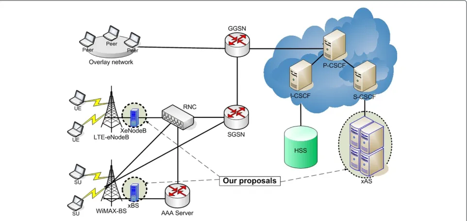
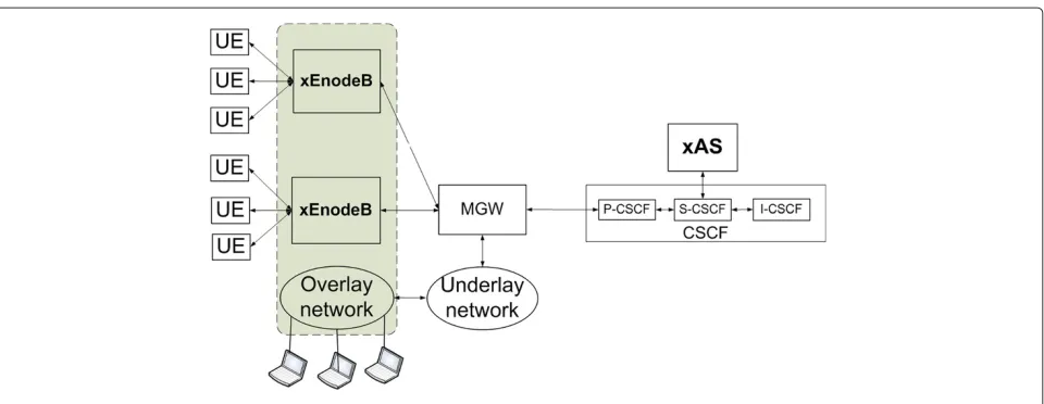
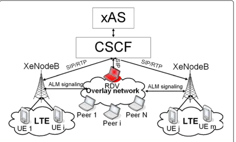
WiMAX has two types of interconnectivities with other wireless networks such as LTE (3GPP): loose couple and tight couple [22]. Figure 2 shows how loose couple inter-working utilizes the AAA-server of a 3GPP network. Data streams are not passed through the core network of a 3GPP LTE system. This method guarantees the indepen-dence of WiMAX network; however, it results in high handover latency between the two networks. The han-dover between WLAN and UMTS was studied [23], and the average handover latency results for loose couple and tight couple were found to be 400 and 150 ms, respec-tively. Therefore, this option is not suitable for real-time services. On the other hand, Figure 3 shows that a tight couple does apply to a radio network controller (RNC) and to the core network (SGSN and GGSN). The WiMAX’s BS connects to WCDMA’s RNC or SGSN directly. The advantage of this mode is that it reduces the handover latency and guarantees a seamless handover. In fact, it is possible to provide real-time services for WiMAX sub-scribers via IMS and the tight couple connectivity with LTE. Figures 2 and 3 also show the proposed blocks of xBS (in WiMAX), XeNodeB (in LTE), and xAS and their positions inside the network (Figure 4). These blocks are essential in order to provide our distributed scalable video conferencing services on WiMAX-LTE networks.
3.2 Design requirements
The main target of this section is to provide the 4G mobile terminals the capability of using a distributed video con-ferencing service based on the ALM-based overlay net-work to save the cost of expensive MCU use as well as reducing the redundant signaling and data forwarding required by that overlay network. The solution is built based on IMS’s standards and 4G infrastructure. The main requirements of the design are the following:
• Utilize available resource and information which can be easily obtained from the LTE-WiMAX
Figure 2Loose couple of interworking between LTE-WiMAX and IMS.
• Discard the standard centralized architecture that uses a MRFC thereby reducing the total expense of the entire solution and avoid the single point of failure while still maintaining multi-party conferencing features
• Utilize floor control, a mechanism which coordinates simultaneous access to shared resources in
multimedia conferences. Floor control allows applications and users to gain safe and mutually exclusive or non-exclusive access to the shared
resources. Floor control can be used to avoid or resolve conflicts among simultaneous media inputs. For example, at any given time, the moderator of a floor can ensure that only one person is heard by other participants or that one person types (writes) into a shared document. In our proposal, floor control is defined as the mechanisms with which to manage a conference session such as join-leave, pause-return, and application layer handover [24]. Floor control is required to provide a well-managed conference
Figure 4LTE-WiMAX IMS-based distributed conference.
service. Since floor control has not yet been
considered for a distributed architecture, we need to find a solution to apply floor control mechanisms into our ALM-based conferencing architecture
• Support a seamless integration among the
LTE-WiMAX mobile terminals and the ALM-based conferencing platform during a mobile video
conferencing session such as join-leave, pause-return, soft handover, heartbeat, etc.
• Provide a quality of service (QoS)-guaranteed mechanism for QoS-required ALM conferencing architecture systems
3.3 Proposed protocol of the IMS-based LTE-WiMAX distributed conferencing service
3.3.1 New features of our proposal
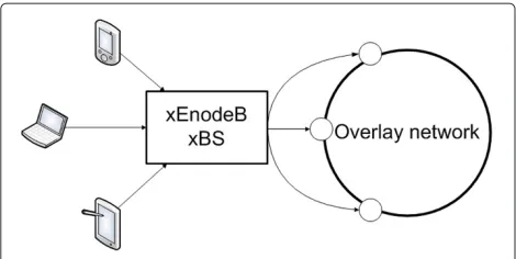
In this proposal, eNodeB(s)-xBS(s) are used as the proxy servers for bridging between the participating UEs and the distributed conference. It will represent the UE in the overlay network as a representative overlay node. An AS will be used primarily to manage the floor control and the mapping between UEs and their proxy eNodeB-xBS. We call the extended version of eNodeB that supports the ALM’s protocol the XeNodeB and the extended version of the AS the xAS.
To obtain these design requirements (described in Section 3.2), we propose new solutions to support a new version of eNodeB-xBS:
• Application level soft handover: since our proposal is based on an overlay network in which the peers are arranged in layers and clusters according to their connection conditions (bandwidth, delay,
packet-loss, computational capacity, availability), it is mandatory to update this information whenever it is changed during the communication session. The
xBS(s)-eNodeB(s) are used as proxies for wireless terminals to participate in the overlay network, and so, when the wireless terminals change their base stations during the handover process at the wireless layer, the handover process must also be performed at the handover process at the overlay network (application level). This is required because each base station has its own capacity and available bandwidth, and each wireless terminal has to update their resource reservation process before attaching to another base station. Since the new base station will represent the wireless terminal in the overlay network, the new connection conditions must be updated to the overlay network before the
connection can be actually released in the radio layer to finish the handover process. If the old overlay node is deleted before the handover process finishes, all forwarding traffic going through that node will be discarded. Therefore, for a smooth and effective soft handover process in the overlay network (application level), it is necessary to have a duplicated node in the overlay until the handover process at the radio layer is finished. The application layer handover can also reduce the unnecessary cost to the mobile
subscribers that occurs during pause-return.
Figure 5Representing nodes during join-leave.
representative xBS-eNodeB level to prevent the UEs from being resource abused.
• Pause-return: during the pause-return process of the UE(s) from the conference session, the representative eNodeB-xBS can do the data forwarding work for the UE(s) in the overlay network. This new feature saves considerable valuable radio resources on the part of the wireless mobile terminals.
• Join-leave: while joining-leaving a conference, each UE has to pass through a QoS resource reservation process. The QoS parameters (bandwidth, delay, packet-loss) of the wireless connection is thereby confirmed for each UE. The representative
eNodeB-xBS will create a node in the overlay for each UE that it represents. The position of that newly created overlay node in the media distribution tree is determined by the application-aware cost function based on the confirmed QoS resource reservation of each UE. Hence, the representative eNodeB-xBS can create several nodes in the overlay network according to the number of UEs it is representing as shown in Figure 5. Our proposal will enable this process with the extended version of the xBS-eNodeB. The proposal has been briefly introduced in [20].
Many questions have been posed about whether the eNodeB(s)-xBS(s) have enough computational capacity and intelligence to enable the functionalities required in a distributed architecture. The feasibility of using
eNodeB-xBS for advanced features has been investigated in [25,26]. Moreover, the relay stations with extra capac-ities have been introduced to the WiMAX networks [27] and they can be also a perfect fit to our solution.
3.3.2 Detailed descriptions of XeNodedB and xAS
Figure 6 shows the extended features of the XeNodeB-xBS:
• Participate as a node in the overlay’s network
• Transfer or forward data and control messages
• Scalable video layer registration. The video codec can be AVC or SVC, and a video transcoder [28] can be applied to transcode between these two video codecs.
To achieve these features, each XeNodeB manages the following:
• Routing tables:
– A listing UE participants served by that XeNodeB. The list contains the UEs’ IP, overlay role (source-relay-forwarding), status (idle-active), and registered video layer(s) (base-enhanced).
– Tables are updated based on the status (idle-left-active) of their managing UEs.
• A list of peers in the distributed conference
containing the peer’s IP, distance (cost to reach that peer from the current XeNodeB).
• An event processor:
– Updates the participant list in join-leave, pause-return and handover operations and – Reports to xAS regarding the status
(idle-left-active) of its managing UEs.
• An overlay interface:
– The interface between its participating UEs and the overlay network and
– Filters forwarding packets and send them back to the overlay network to save UE’s capacity.
• A signal processor:
– Obtains UEs’ status (availability, its available QoS level) from the xAS and
– Sends back UE’s status to the distributed conference via the overlay interface as required.
• The QoS and video layer registration: Checks each UE’s available QoS and its registered video layers to see if they can be matched together.
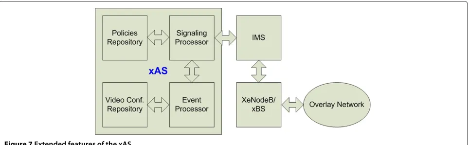
Figure 7 shows the extended features of the xAS:
• Floor control for the video conferencing application: conference ID, participant’s list, participant’s status
• Obtain UE-related information from the
LTE-WiMAX network and forward to the overlaying nodes
• QoS guarantee, conference’s QoS policies
This xAS can be developed by operators and service providers and placed inside of a network. It then provides distributed video conferencing service for 4G users. xAS manages the service, and operators are usually included in providing such service. To achieve these features, each xAS manages a:
• Conference list: contains conference ID, IP, XeNode ID, conference status (in progress-terminated)
• Signaling processor:
– Receives requests from XeNodeB’s signaling processor and
– Interrogates the UE’s (QoS, availability, etc.) from the home subscriber server and IMS and sends it back to XeNodeB’s signaling
processor,
• Event processor:
– Receives updates from XeNodeB’s event processor about leave-join, pause-return, and handover
– Updates the conference list
• Conference policy, including the following:
– Starting time, duration, maximum number of participants
– QoS requirements – Billing information
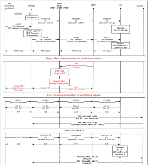
Figure 8 shows the call flow when a UE wants to par-ticipate in or leave a distributed video conference. Firstly, when turned on, it automatically sends a REGISTER mes-sage to its XeNodeB. The XeNodeB then updates its routing table and sends (eNodeB-ID, UE-SIP-account) to the xAS. This information will be stored in the xAS’s conference list. When the UE wants to initiate its partic-ipation in a distributed conference, it sends the INVITE (conference ID, layer registration) message, containing the maximum number of enhancement layer(s) it wants to receive from the conference multicast tree, to the con-trolling XeNodeB. The XeNodeB converts the layer(s) number to a QoS parameter which is comprehensible to the policy charging rule function (PCRF). Next, the invite message is forwarded to the xAS for mapping among the conference-ID, UE-SIP-account, and XeNodeB-ID in the xAS’s conference list. At the same time, the INVITE message is forwarded to the policy charging enforcement function (PCEF) using the authorization-authentication request (AAR) message sent by the CSCF. The PCRF will check whether the UE has subscribed for enough QoS resource in order to receive the required number of enhancement layers. If its subscription is sufficient, a resource reservation request will be sent to the PCEF to activate the resource policy for the UE to join the dis-tributed conference [29]. The confirm resource is then
Figure 8The UE join-leave process to-from the overlay-based distributed conference with QoS support.
reported to the xAS for updating of the QoS require-ments and of the billing information in the conference policy [26]. Upon receiving the QoS confirmation, the XeNodeB sends an ALM’s JOIN-REQ (UE-SIP-account, layer-reg) message to the ALM group to represent the UE participating in the ALM tree. After a new node has been
(UE-ID) is sent to the ALM tree for a leaving request. The UE’s record is then removed from the xAS’s conference list.
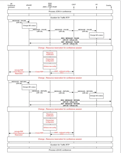
Figure 9 illustrates the pause-return operations of a UE over a distributed video conferencing service.
During the conference session, the UE may want to sus-pend the service (it does not want to receive or transmit video streams and signaling messages for a time duration) while preferring to be able to return to the ALM group with the smallest delay afterwards. Of course, if the sus-pending time is too long, the UE will be automatically discarded from the ALM group. When a UE wants to become idle, it sends the PAUSE (UE-SIP-account) to the XeNodeB and to the xAS so that they can update their lists. The XeNodeB then automatically sends a PAUSE-REQ (UE-ID) to the ALM group. The ALM group will stop sending bit streams and signaling messages (HEART-BEAT) to the specific UE-ID, thus placing that UE on the waiting list of the ALM group within a certain time period. If the UE returns to the conference within that time period, it will only have to send a RETURN (UE-SIP-account, UE-ID) to the RDV point of the ALM group and then comes back to the ALM tree. If the UE is idle beyond the set time period, it will automatically be discarded from the ALM group’s waiting list. When working in the idle mode, the UE returns its reserved resources to the net-work via a resource modification process. The resource will be given back to the UE when it returns.
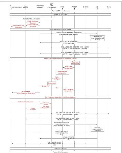
Figure 10 shows a UE going through a while participat-ing in a distributed conference.
This process is compatible with the 3GPP recommenda-tion on the radio layer handover process in LTE-WiMAX [30-32]. The radio layer handover process starts with the hard handover of the mobile terminal in the radio level between two eNodeB-xBS [33]. It starts when the original eNodeB finds that the radio connection with the UE is reducing to below a predefined level. The original eNodeB will contact the destination eNodeB with a HO request. If everything is ok, the destination eNodeB will acknowledge with a HO response. The origi-nal eNodeB notifies the UE that it can start the handover process. At the service layer, when a UE is about to be handed over from the source to the destination XeN-odeB, the destination eNodeB sends an APPLICATION-LAYER-HANDOVER-SUBSCRIBE (Des-eNodeB-ID, UE node id) to the xAS. The xAS will then update its list with this information and response the destination eNodeB with an APPLICATION-LAYER-HANDOVER-SUBSCRIBE-ACK. Afterwards, the destination eNodeB can create a duplicated node in the overlay by using REQ:MESSAGE-CREATE-DUP-NODE. The duplicated node will manage the data forwarding from the old node while the old node is performing its handover. A response is sent when the duplication is finished and confirmed. A
new resource reservation process is made for the UE to be attached to the new eNodeB.
At this time, two representing nodes are maintained by the two XeNodeBs in the ALM group in order to assure a soft handover process. Even though there are two nodes in the overlay, they are actually sending and receiving identi-cal data. The identiidenti-cal nodes send and receive bit streams as any other normal node in the ALM group thus help-ing the UE to maintain its conference service via both eNodeB-xBS until the old connection is actually broken. However, only the duplicated node has to manage the data forwarding required by the overlay network. After the handover is finished at the radio layer, the source XeNodeB sends a DELETE-DUP-NODE (UE id, layer reg-istration, eNode ID) message to the ALM group and waits to receive the response to confirm that all is finished. It sends a confirmation message to the xAS so that it can be updated. Information regarding the old eNodeB will then be removed from the xAS. The old UE-ID is then removed from the ALM group and only one UE-ID will represent the UE in the conference. The handover process at the service layer is then finished and confirmed.
Figure 11 shows the heartbeat handling process in the distributed conference with the support of the link mea-surement process available at the eNodeB. Heartbeat is the mechanism widely applied in an overlay-distributed architecture, in which peers periodically send short mes-sages to inform other peers about their existence in the overlay. It also receives heartbeats from other peers to update about their existence. Many ALM algorithms have to depend on a heartbeat mechanism to maintain their group. If a UE has to directly respond to all heartbeats it receives, it will soon run out of power and compu-tational capacity. Meanwhile, all information regarding a UE’s availability is available at the managing eNodeB, a simple link measurement interrogation operation trig-gered by the xAS can resolve this problem. Therefore, the XeNodeB will periodically consult the link status to query for the availability of all UEs that are joining the distributed conference under its representative and report back to the xAS.
The XeNodeB will then send back the heartbeats of all the UEs it is representing to the ALM group to signal their availability. For floor control purposes, the ALM-based distributed conference will update the list of peers participating in the conference to the xAS.
4 Prototype and performance evaluation
4.1 Evaluation method
Figure 11Handling heartbeat operation in a distributed conference.
using a LTE-WiMAX infrastructure with IMS support. We used OpenIMS [35]-open as the IMS core and the Mobicents platform to build the xAS and XeNodeB. A dis-tributed conferencing service was built based on [8]. A ‘rendezvous’ point in the overlay and the XeNodeBs are equipped with a SIP interface so that the overlay can com-municate with the xAS via the IMS core. We constructed three evaluation scenarios run with different numbers of participants, in which four UEs participate via the IMS core:
• Scenario 1: Centralized IMS-based video
conferencing using MRFP, as recommended in the standards (i.e., LTE, WiMAX, IMS)
• Scenario 2: Conventional ALM-based distributed video conferencing service
• Scenario 3: Our proposed IMS-based distributed video conferencing service for LTE-WiMAX networks
Scenario 1 is widely used as the standard architecture to provide the video conferencing services over wireless mobile networks.
Scenario 2 can be referred to as the Web-NGN con-verged multimedia conferencing system. The most troublesome problem with this scenario (and which is investigated further in the evaluation) is that the mobile terminals are obligated to handle all the unnecessary signaling and data forwarding traffic that any other peer in the ALM group may handle (even though some peers may be workstations on fixed networks with unlimited power, high computational capacity and high band-width connections). Therefore, the limited power of the mobile terminals will be rapidly used up and their poor radio resources filled up almost exclusively by the ALM’s unnecessary signaling and data forwarding traffic.
We selected these three scenarios because they help to explain how our proposal (scenario 3) can sharply reduce the redundant signaling and data forwarding traffic com-pared to the situation with the conventional overlay-based architecture (scenario 2). By comparing our solution, sce-nario 3, with the standard centralized solution (scesce-nario 1), we show that our proposed scenario has an equiva-lent traffic to the centralized architecture but with all the advantages (delay, flexibility, scalability, lower cost, single point of failure) of a distributed architecture as stated in Section 2.
In all three scenarios, each peer sends 100 audio pack-ets for audio conferencing and 300 video frames for video conferencing. The data was measured three times for each number of participants in each scenario for convergence purposes. In each of these scenarios, we built and applied the following:
• A prototype of our proposed distributed architecture with the sample nodes in the overlay network
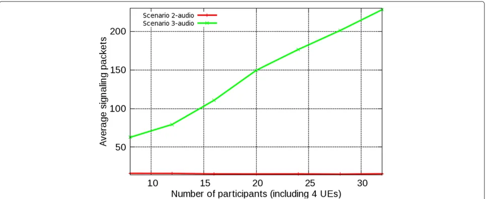
Figure 13Average number of signaling messages required during an audio conferencing session for each of the three scenarios.
• A prototype of the proxy nodes running on BSs
• A real audio conference open source software (sample audio packets obtained from real audio conference sessions)
• A prototype of a video conferencing service on the simple overlay network and our proposed
architecture
• A real SIP client
• An open source IMS platform (OpenIMS) 4.2 Evaluation results
The numerous advantages of the distributed architecture over the centralized architecture have been elaborated elsewhere; the main purpose of our research is not to
compare our solution’s performance with that of cen-tralized architecture and prove that our solution has a better performance. Once again, our purpose is to enable video conferencing service via distributed architecture for next-generation wireless networks with only a slight mod-ification of the 4G infrastructure and the IMS platform. To establish the distributed architecture over a mobile net-work, we have to resolve the crucial problem posed by requiring a high bit rate of wireless terminals. Therefore, we evaluate the performance of our proposal in terms of bit rates for data and signaling plans.
Figures 13 and 14 show the average number of sig-naling messages calculated at UE interfaces during an audio-video conferencing session for all three scenarios
Figure 15Average number of data packets sent-received at each participant during an audio conferencing session for scenarios 2 and 3.
(Figure 13) and for scenarios 2 and 3 (Figure 14). The result shows that scenario 2 needs to use much more sig-naling packets than scenario 3 to maintain a distributed conference. Our solution, scenario 3, performs better because most of the signaling loads have been processed by the XeNodeBs.
Figures 15 and 16 show the comparison between the average data traffic monitored on UEs in scenarios 2 and 3 for an audio-video conference. Apparently, the data traffic in scenario 3 is lower than in scenario 2 because the XeNodeBs have automatically routed the forwarding traffic for its managing UEs in the overlay. Therefore, the UEs only have to process the data traffic that is intentionally sent to them. We can hereby confirm that
our scenario 3 has sharply reduced the traffic that mobile terminals have to contribute to maintain the overlay network.
Figure 13 also shows that scenarios 1 and 3 require a similar number of signaling packets on UEs. We can conclude that our scenario 3 imposes a requirement sim-ilar to that of the standardized centralized scenario but with all benefits of the distributed architecture that are so obviously lacking in centralized architecture.
Figure 17 shows that the average data traffic at a UE in scenario 3 is slightly higher than the average UE traffic in scenario 1 but far less than the MCU’s average traf-fic in scenario 1. Apparently, the signaling and data traftraf-fic in scenario 1 is the smallest because it does not have to
Figure 17Average number of data traffic sent-received to-by each participant-MCU during an audio conferencing session of scenario 1 and scenario 3.
maintain a distributed architecture, and the MCU is in charge of almost everything which comes with an exces-sively high cost. Our proposed scenario 3 has fulfilled our design requirements to reduce the data traffic at wireless terminal while maintained all the benefits of a distributed architecture.
5 Conclusions
This paper proposes a new architecture for the inter-connectivity between UEs running on the LTE-WiMAX infrastructure and participating in an overlay-based dis-tributed conference. Experimental results from the proto-type have shown a great reduction in signaling traffic as well as in the data traffic handled by each UE and by the core network. The average bit rate required at the wireless terminals in our distributed architecture is equivalent to that of centralized architecture while it is much less than that required for conventional overlay networks.
Various conferencing scenarios such as join-leave, pause-return, application layer handover, and heartbeat have been considered in the prototype. The main contri-bution is that it enables an overlay-based video conference with all the benefits of a distributed architecture and with-out the disadvantages of too much traffic stressing the mobile terminals’ wireless connections (a mandatory cri-terion for wireless networks). The bit rate required of wireless peers in our proposed distributed architecture is equivalent to that of a standard centralized case (based on results obtained from evaluating our prototype of audio and video distributed conferencing services). The results confirm that it is possible to apply distributed archi-tectures in next generation of wireless networks. Taking advantage of 4G’s BSs means that the total cost of the conferencing services can be reduced and that these ser-vices can be provided with a minimum modification of
relevant standards. The proposal replaces the standard centralized architecture of the IMS-based conference by a more robust solution utilizing intelligence and com-putational capacity of 4G’s BS(s). The prototype of our proposed distributed architecture for a multimedia ser-vice has shown that it can be integrated well into a 4G network. Its distributed nature leads to a considerable reduction in cost as well as more flexibility and scala-bility combined with smaller delay. The architecture can also be applied in WiMAX networks with a reasonable amount of modifications. The security for this distributed architecture can be inherited from the authentication and encryption mechanisms applied by LTE, WiMAX, and SIP technologies.
Our solution profits from all the advantages of dis-tributed architecture, such as flexibility, more scalability, smaller delay, and lower cost. As a trade-off, some of the computational capacity of the infrastructure (core net-work and eNodeB-xBS) is required to enable distributed architecture in a mobile network. However, this situa-tion is not really a disadvantage because the counterpart computational capacity required at the centralized media server (MRFC) is now distributed over the network infras-tructure (eNodeB(s)-xBS(s) and the core network).
Abbreviations
3GPP: 3rd Generation Partnership Project; 4G: fourth generation network; AAA: authentication, authorization, and accounting; ALM: application layer multicast; AS: application server; ASN: access service network; ASP: access service provider; BS: base station; BSC: base station controller; BWA: broadband wireless access; CSN: connectivity service network; CSCF: call session control function; eNodeB: evolved node B; FCS: floor control server; GGSN: gateway GPRS support node; GPRS: general packet radio service; IMS: IP multimedia subsystem; LTE: long-term evolution; MCU: multipoint control unit; MRFC: media resource function controller; MRFP: media resource function processor; NGN: next-generation network; P2P: peer to peer; P-CSCF: Proxy-CSCF; PCRF: policy and charging rule function; QoS: quality of service; RNC: radio network controller; RTP: real-time transfer protocol; SIP: session initiation protocol; SGSN: serving GPRS support node; UE: user equipment; UMTS: universal mobile telecommunications system; WCDMA: wideband code division multiple access; WLAN: wireless local area network; WiMAX: worldwide interoperability for microwave access; xBS: extended base station.
Competing interests
The authors declare that they have no competing interests.
Acknowledgements
This research work is partly supported by POSEIDON, a French national project on the evaluation of the next-generation wireless network and its multimedia services. The authors are grateful to Quoc Tuan Tran, Quang Hoang Nguyen, and Hongguang Zhang for their prototype development and helpful discussions.
Received: 22 October 2012 Accepted: 22 May 2013 Published: 19 June 2013
References
1. M Hossain, M Atiquzzaman, Cost analysis of mobility protocols. Telecommunication Syst, 1–15. doi:10.1007/s11235-011-9532-2 2. L De Cicco, S Mascolo, V Palmisano, inProceedings of the 18th International
Workshop on Network and Operating Systems Support for Digital Audio and Video,Vancouver, 1-3 Jun 2011. Skype video responsiveness to bandwidth variations (ACM New York, 2008), pp. 81–86
3. SA Baset, H Schulzrinne, inProceedings of the 25th IEEE International Conference on Computer Communications. An analysis of the skype peer-to-peer internet telephony protocol (IEEE Barcelona, 23–29 April 2004), pp. 1–11
4. R Spiers, N Ventura,An Evaluation of Architectures for IMS Based Video Conferencing. (University of Cape Town, Rondebosch South Africa, 2009) 5. A Garcia, Nefsis offers both free and for-pay versions.
eWeek27(19), 40–41 (2010)
6. I Ekin Akkus, O Ozkasap, M Reha Civanlar, Peer-to-peer multipoint video conferencing with layered video. J. Netw. Comput. Appl.34(1), 137–150 (2010)
7. TA Le, H Nguyen, inIEEE GLOBECOM 2011-Communication Software, Services, and Multimedia Applications Symposium (GC’11-CSWS). Perception-based application layer multicast algorithm for scalable video conferencing (IEEE Houston, 5–9 Dec 2011), pp. 1–5
8. TA Le, H Nguyen, inThe Second International Conference on Ubiquitous and Future Networks (ICUFN 2010). Centralized and distributed architectures of scalable video conferencing services (IEEE Jeju Island, 16–18 Jun 2010), pp. 394–399
9. 3rd Generation Partnership Project, IP Multimedia Subsystem (IMS), Stage 2 (Release 5). 3GPP TS 23.228.5, 8–10 (2004)
10. F Belqasmi, C Fu, M Alrubaye, R Glitho, Design and implementation of advanced multimedia conferencing applications in the 3GPP IP multimedia subsystem. IEEE Commun. Mag.47(11), 156–163 (2009) 11. A Buono, S Loreto, L Miniero, SP Romano, A distributed IMS enabled
conferencing architecture on top of a standard centralized conferencing framework [IP Multimedia Systems (IMS) Infrastructure and Services]. IEEE Commun. Mag.45(3), 152–159 (2007)
12. 3gpp, Conferencing using the IP multimedia (IM)core network (CN) subsystem-ts 24.147. Tech. rep (2008)
13. SE Deering, DR Cheriton, Multicast routing in datagram internetworks and extended LANs. ACM Trans. Comput. Syst. (TOCS).8(2), 85–110 (1990)
14. C Diot, BN Levine, B Lyles, H Kassem, D Balensiefen, Deployment issues for the IP multicast service and architecture. IEEE Netw.14(1), 78–88 (2000) 15. C Luo, W Wang, J Tang, J Sun, J Li, A multiparty video conferencing
system over an application-level multicast protocol. IEEE Trans. Multimedia.9(8), 1621–1632 (2007)
16. JG Andrews, A Ghosh, R Muhamed,Fundamentals of WIMAX. (Prentice Hall, New York, 2007)
17. QT Tran, TA Le, H Nguyen, in2011 15th International Conference on Intelligence in Next Generation Networks (ICIN) - From Bits to Data, From Pipes to Clouds (ICIN 2011). WiMAX-based overlay conferencing service (Berlin, 4–7 Oct 2011), pp. 17–22
18. 3gpp, UTRA-UTRAN Long Term Evolution (LTE) and 3GPP System Architecture Evolution (SAE) (2005)
19. P Beming, L Frid, G Hall, P Malm, T Noren, M Olsson, G Rune, LTE-SAE architecture and performance. Ericsson Rev.3, 98–104 (2007) 20. TA Le, H Nguyen, N Crespi, in2012 IEEE Wireless Communications and
Networking Conference: Services, Applications, and Business (IEEE WCNC 2012 Track 4 SAB). IMS-based distributed multimedia conferencing service for LTE (Shanghai, 1–4 April 2012), pp. 3210–3214
21. W Forum, WiMAX Forum Network Architecture - Architecture, detailed Protocols and Procedures - Policy and Charging Control. Tech. rep (2009) 22. F Xu, L Zhang, Z Zhou, Interworking of Wimax and 3GPP networks based
on IMS [IP Multimedia Systems (IMS) Infrastructure and Services]. Commun. Mag. IEEE.45(3), 144–150 (2007)
23. J Song, S Lee, D Cho, in2003 58th Vehicular Technology Conference, vol. 4. Hybrid coupling scheme for UMTS and wireless LAN interworking (Orlando, 6–9 Oct 2003), pp. 2247–2251
24. X Wu, P Koskelainen, H Schulzrinee, Use of session initiation protocol (SIP) and simple object access protocol (SOAP) for conference floor control protocol (SOAP) for conference floor control. Tech. rep., Internet draft, Internet Engineering Task Force (2003)
25. K Daoud, P Herbelin, N Crespi, inIEEE 19th International Symposium on Personal, Indoor and Mobile Radio Communications. UFA: Ultra flat architecture for high bitrate services in mobile networks (Cannes, 15–18 Sept 2008), pp. 1–6
26. K Daoud, P Herbelin, N Crespi, in1st IFIP Wireless days. One-node-based mobile architecture for a better QoS control (Dubai, 24–27 Nov 2008), pp. 1–5
27. P Mach, R Bestak, Z Becvar, Optimization of association procedure in WiMAX networks with relay stations. Telecommunication Syst, 1–8. doi:10.1007/s11235-011-9661-7
28. R Garrido-Cantos, J De Cock, J Martínez, S Van Leuven, A Garrido, Video transcoding for mobile digital television. Telecommunication Syst, 1–12. doi:10.1007/s11235-011-9594-1
29. W Zhuang, YS Gan, KJ Loh, KC Chua, Policy-based QoS architecture the IP multimedia subsystem of UMTS. Netw. IEEE.17(3), 51–57 (2003) 30. A Racz, A Temesvary, N Reider, in16th IST Mobile and Wireless
Communications Summit. Handover performance in 3GPP long term evolution (LTE) systems (IEEE Budapest, 1–5 Jul 2007), pp. 1–5 31. P Xu, X Fang, R He, Z Xiang, An efficient handoff algorithm based on
received signal strength and wireless transmission loss in hierarchical cell networks. Telecommunication Syst, 1–9. doi:10.1007/s11235-011-9667-1 32. A Ulvan, R Bestak, M Ulvan, Handover procedure and decision strategy in
LTE-based femtocell network. Telecommunication Syst, 1–16. doi:10.1007/s11235-011-9599-9
33. RY Kim, I Jung, X Yang, CC Chou, Advanced handover schemes in IMT-advanced systems [WiMAX/LTE Update]. Commun. Mag. IEEE.
48(8), 78–85 (2010)
34. TA Le, QT Tran, QH Nguyen, Multi-P2P prototype. http://code.google. com/p/multi-p2p/. Accessed 6 Dec 2009
35. F Fokus, Open IMS core. http://www.openimscore.org. Accessed 5 Dec 2012
doi:10.1186/1687-1499-2013-170
![Figure 1 3Gpp IMS conference architecture [12].](https://thumb-us.123doks.com/thumbv2/123dok_us/965925.1118531/3.595.306.542.89.202/figure-gpp-ims-conference-architecture.webp)