R E S E A R C H
Open Access
Spectral efficient IR-UWB communication
design for low complexity transceivers
Vijaya Yajnanarayana
1*, Satyam Dwivedi
1, Alessio De Angelis
2and Peter Händel
1Abstract
Ultra wideband (UWB) radio for communication has several challenges. From the physical layer perspective, a signaling technique should be optimally designed to work in synergy with the underneath hardware to achieve maximum performance. In this paper, we propose a variant of pulse position modulation (PPM) for physical layer signaling, which can achieve raw bitrate in excess of 150 Mbps on a low complexity in-house developed impulse radio UWB platform. The signaling system is optimized to maximize bitrate under practical constraints of low complexity hardware and regulatory bodies. We propose a detector and derive its theoretical performance bounds and compare the performance in simulation in terms of symbol error rates (SER). Modifications to the signaling, which can increase the range by 4 times with a slight increase in hardware complexity, is proposed. Detectors for this modification and a comparative study of the performance of the proposed UWB physical layer signaling schemes in terms of symbol error rates are discussed.
Keywords: Pulse position modulation; Sensor networks; Time-to-digital converter; Ultra wideband; UWB communication
1 Introduction
The radio technologies for communication systems gener-ally employ a non-overlapping radio frequency (RF) spec-trum. That is, every radio technology like GSM, 3G, Blue-tooth, etc. uses a distinct RF spectrum. There are several radio technologies, and several new ones are emerging; as a result, RF spectrum is becoming more premium and more scarce. Communication systems using ultra wide-band (UWB) offer a promising solution which can coex-ist with other radio technologies. This coexcoex-istence also saves expensive spectrum licensing fees [1,2]. The Federal Communications Commission (FCC) adopted license-free UWB operation in the United States of America [3]. This has resulted in 7.5 GHz of spectrum available for UWB systems. One of the direct consequences of this large bandwidth is the ability to achieve very high data rates, as given by the Shannon-Hartley theorem. Wide bandwidth also enables innovative system design such as trading data rate to avoid costly channel estimation tech-niques in [4] or designing the analog transmit and receive
*Correspondence: [email protected]
1Department of Signal Processing, KTH Royal Institute of Technology, Fack, 100 44 Stockholm, Sweden
Full list of author information is available at the end of the article
structure with non-idealities in [5]. In general, there is a wide scope of data rate, range, and other parameters that can be traded off based on the application [6-8].
There are several ways in which a signal can be spread to large bandwidths. The most popular methods include fre-quency hopping (FH) [9], orthogonal frefre-quency-division multiplexing (OFDM) [10], direct-sequence spread spec-trum (DS-SS) [11], and time-hopping impulse radio (TH-IR) [12]. UWB based on OFDM and TH-IR have gone in to IEEE 802.15.3a and IEEE 802.15.4a standards. TH-IR schemes are most popular as they provide better performance and complexity trade-offs [7].
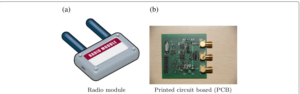
The use of impulse signaling (TH-IR) was proposed by Win and Scholtz in the 1990s. Their work published in [12-14] contributed significantly toward the adaptation of TH-IR for UWB. High bandwidth enables the UWB transceiver to generate narrow impulse signals; this fine time resolution can yield accurate position localization and ranging. This has enabled the application of UWB for high-precision ranging and localization. Our objective is to utilize the same platform for both communication and localization. Figure 1 shows a graphical depiction of an in-house developed IR-UWB platform for ranging and com-munication. It uses a low-cost pulse generator to generate
(a)
(b)
Figure 1Iconic model of the in-house developed impulse radio UWB-platform of size 6×4 cm.Iconic model of the in-house developed impulse radio UWB-platform of size 6×4 cm for ranging and communication working in the 6-GHz regime with separate RX and TX antennas from Greenwave Scientific (details available at [19]).
sub-nanosecond pulses using step recovery diode (SRD), as described in [15]. The characterization and modeling of the UWB platform for a distance measurement system can be found in [16,17]. A detailed architectural descrip-tion and experimental ranging result from a prototype of the platform have been published in [18]. The power and range of the transceiver can be easily traded by controlling the amplitude, duty cycle, and number of pulses per bit of transmission.
There are several commercial companies which develop IR-UWB products, including [20-24]. Companies like DecaWave and BeSpoon develop 802.15.4a standard spe-cific IR-UWB products [23,25]. The physical layer signals of these UWB radios are defined by the standard. There are some companies like Time Domain and Ubisense which develop non-standard or custom-made communi-cation and localization solutions [26,27]. In these UWB radios, the physical layer signaling does not adhere to any standards. The work proposed in this paper con-siders a methodology to maximize the communication rate through custom physical layer signaling, subject to hardware, and regulatory constraints.
The main motivation for the work is from the require-ment that many UWB applications need to perform local-ization and communication using the same radio module [6,28]. The UWB radios of Time Domain and Ubisense both have localization and communication capabilities; however, these radios have minimal communication capa-bilities of few Kbps and physical layer signaling in them is not made public. This paper is also motivated by the fact that extensive research can be found on the design of hardware platforms and algorithms for localization and communication strategies in [6,18,29], However, how to optimize the physical layer signaling for communica-tion in view of constraints from cost-effective hardware and regulatory bodies is not a well studied problem. The achievable bitrate for the proposed methods in this paper
depends on the hardware parameters of the UWB plat-form. The proposed methods suggest that the in-house developed UWB radio shown in Figure 1 can achieve bitrates up to 150 Mbps. The in-house UWB platform uses pulse round-trip time (RTT) for localization. It has a range of about 10 m with an accuracy of 30 cm in practi-cal scenarios. It has a digital processing section based on a field-programmable gate array (FPGA), which interfaces with analog UWB sections to generate required analog pulsed waveforms for transceiver operation. The modu-lator and demodumodu-lator algorithms proposed in this paper can be programmed in FPGA, for processing UWB com-munication signals. This paper proposes two signaling schemes with one requiring higher complexity in modu-lation and demodumodu-lation, however can increase the range by nearly 4 times without compromising on the bitrate. This is believed to have an interest in its own right, as it corresponds to (or outperforms) today’s state of the art. Although the work considers the in-house developed UWB radio (Figure 1) for demonstrating the techniques, the results are of general importance which can enable engineers to follow similar methodology to exploit the hardware and spectrum to achieve a higher possible range and bitrate.
In this context, through this paper we propose a method for communication using low-cost and low complexity hardware architecture which can perform ranging, local-ization, and communication. The main contributions of this paper are summarized below:
• A spectrally more efficient modulator, which can improve the range of the communication by introducing the memory between symbols called with-memory modulator, is proposed. This has a marginal increase in complexity of modulator and demodulator algorithms with an increase in range by 4 times.
• A no-memory modulator is analyzed by deriving an expression for the symbol error rate (SER)
performance. A detector algorithm for the no-memory modulator is proposed, and its SER performance is verified through simulation. • The detector algorithm for the with-memory
modulator is proposed and detector performance of no-memory and with-memory signaling are compared in simulation.
This paper is organized as follows: In Section 2, we discuss the system model and pulse shapes used in the impulse radio. Section 3 discusses UWB constraints. Section 4 is on low complexity UWB hardware plat-form for localization and communication, and Section 5 details the design of physical layer signal construction and modulator algorithms. Section 6 describes detectors and their performance in terms of symbol error rates. Finally, Section 7 details the conclusions from the design and results demonstrated.
2 Pulse construction and system model
A wide range of pulse shapes have been explored for UWB communication from rectangular to Gaussian [30]. Gaussian pulses and their derivatives, usually called monopulses, are effective due to the ease of construction and good resolution in both time and frequency. In many cost-effective hardware designs, these shapes are gener-ated without any dedicgener-ated circuits. A simple transistor or diode, which is turned ‘on’ and ‘off ’ to generate a nar-row rectangular pulse, will form an approximate Gaussian shape due to the imperfections in micro-electronic design [31].
The time domain Gaussian pulse with mean μ and
varianceσ2can be written as
1 2πσ2e
−(t−μ)2
2σ2 (1)
A more useful form of this equation for system design is defined in [31]. This is a scaled version of (1) with zero mean and varianceτ2/4π. This is given by
s(t)= −e−2π(τt)2 (2)
In a typical UWB device, when the signal passes through the UWB antenna, it will have a differentiation effect on the signal. A similar effect is observed when the receiver receives the pulses. The first- and second-order Gaussian pulses are given by
s(t)= ds(t)
For analytical and simulation analysis, we have used the power normalized second-order Gaussian pulse as shown in (5).
Several modulation techniques are proposed in the lit-erature using narrow pulses [12,32]. Primarily, they are variants of pulse position modulation (PPM), binary phase shift keying (BPSK) or on-off keying (OOK). Since our objective is to employ low complexity hardware structure to perform synchronized ranging and communication, a variant of PPM-based signaling for communication is used. This can reuse the hardware structure (having round trip time (RTT) calculation logic for ranging) for detection and demodulation of physical layer signal. This is further illustrated in Section 4.
The system model comprises of three parts; transmitter, channel, and receiver, as shown in Figure 2. The transmit-ter generates the PPM variant signal. This is a modified pulse specified in [12] with 1 symbol per pulse and no time hopping. The transmitted output signal is given by
Wtr(t)=
is a parameter coming from the constraints of the typi-cal UWB hardware which will be explained later,is the modulation index, and log2M is the modulation order. Though in our model each symbol is defined by one pulse, it can be easily extended to multiple pulses for each sym-bol so that communication rate and detectability can be traded.
In UWB applications which use ranging for localiza-tion, the detectors rely on the first arriving path or line of sight (LOS); this is in contrast to traditional channel measurement and modeling. However, for extremely short distance high-speed communication with highly direc-tional antennas, we can adopt a deterministic single path channel [8]. These short distance high-speed UWB appli-cations include transferjet and wireless USB (wUSB). The message information is embedded in the time axis of PPM signals. Due to the high time resolution of UWB signals, the performance of the system is sensitive to the timing jitter and synchronization [33,34]. The effect of channel, imperfect timing/synchronization, and receiver front end thermal noise will cause errors while demodulating the PPM signals. We combine the effect of channel, imper-fect timing/synchronization, together with receiver front end to introduce a random jitter (shift on time axis) along with noisen(t)as shown in (7). For analytical and simula-tion purposes, we assume Gaussian distribusimula-tion with zero mean and variance σj2 for jitter [35]. Thus, the received signal is given by
Wrx(t)=Er
is the random jitter in the received signal, and
n(t)is the receiver noise on the received signal.
The third part of the system model is the detec-tor/demodulator, which demodulates the signal repre-sented in (7). In the signal model, a single-user UWB system with no multiple access interference is assumed. However, it is straightforward to extend the techniques proposed in this paper for multi-user system.
In the subsequent sections, we will show how to opti-mally design the modulator and detector to the con-straints of hardware and regulatory bodies. We will also evaluate the theoretical performance of the demodulator for the chosen modulator. In the next section, we will dis-cuss some of the challenges in transmission and detection of UWB pulses from the regulatory bodies and hardware perspective.
3 UWB constraints
The FCC regulation is one of the most popular regulations for UWB, and most of the regulations in other countries
are derived from this regulation. The FCC regulations, [3], define a UWB system as any intentional radiator hav-ing an absolute 10-dB bandwidth greater than 500 MHz or a relative bandwidth greater than 20%. Since UWB systems have to co-exist with other narrowband technolo-gies, the compliance requirements from regulatory bodies for UWB systems are very stringent to ensure that they do not interfere with the existing narrowband systems. This makes the design of UWB for communication challeng-ing. These requirements are generally specified through
constraints on maximal average powerPav and maximal
peak power Ppk. The average power, Pav, is measured using a spectrum analyzer (SA) with resolution bandwidth
(RBW)Bav=1 MHz. Maximal average power constraints
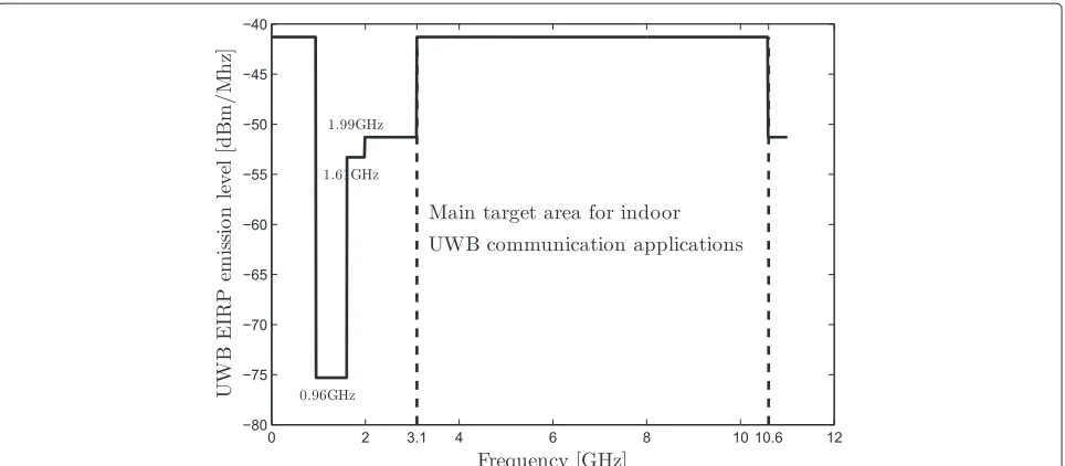
are specified through spectral masks. Figure 3 shows the FCC mandated spectral mask for indoor UWB emissions.
Ppkshould not exceed 0 dBm when measured using an SA with RBW set to 50 MHz.
The pulse repetition rate (PRF) (that is, 1/TSin (6)) of the IR-UWB signal plays a significant role on how the UWB device impacts other narrowband receivers in its range; these receivers are called victim receivers [3]. If the PRF is larger than the bandwidth of the victim receiver, then the emission may appear as noise like to the victim receiver. This effect is proportional to the average power of the UWB signal within the receiver’s bandwidth. If pulse rate is smaller than the victim receiver’s bandwidth, then UWB signal would appear like impulse noise to the victim receiver and the effect is proportional to the peak power of the UWB signal. Thus, at low PRF the output levels are constrained by the limit on peak emission levels and at high PRF by the limit on average emission levels [3]. In [36], the authors specify the existence of two distinct regimes where only one of the two power constraints are active for the IR-UWB signal. For PRF less than 1 MHz, peak constraints are active; for PRF greater than 1 MHz, average power constraints are active. The signaling pro-posed in this paper is optimized for high-rate data
com-munication and hence, high PRF is assumed as1 MHz
yielding only the average power constraint relevant.
4 UWB hardware
Figure 3Spectral mask specified by FCC showing the equivalent isotropic radiated power (EIRP) versus frequency for indoor UWB system.
which carries information in the PPM variant physical layer signaling. This information is further processed by the demodulator algorithm on FPGA to demodulate the symbol. Estimating the round-trip time on unmodulated signal can be used to localize objects as discussed in [18]. Thus, this low complexity transceiver can be used for both localization and communication [38].
In general, in a low complexity UWB transmitter, it is not possible to transmit arbitrary close pulses because of the recovery time required for the micro-electronic devices used in them. This creates a constraint on the sig-naling that the pulses need to be separated by at least a minimum distance equal to the recovery time. This is the reason for having theγnin (6). Also, at the detector it is not possible to resolve between arbitrarily close pulses. Thus, the modulation indexin (6) cannot be arbitrarily small.
5 Modulator
A periodic train of impulses will result in a spectral comb formation in the power spectral density (PSD). This results in an inefficient usage of power and reduces the range of UWB nodes as the spectral peaks can cross the power levels specified in Figure 3. One way to over-come the spectral comb formation is to randomize the pulse interval. As an illustrative example, we can choose the probability density function (PDF) of pulse repetition periodTPRTas a uniform distribution given by
p(TPRT)=
1
2TS−T If T ≤TPRT≤2TS.
0 Otherwise. (8)
HereT, which is TSis the pulse width of the pulses.
TPRT is varied from T instead of 0 to avoid collision
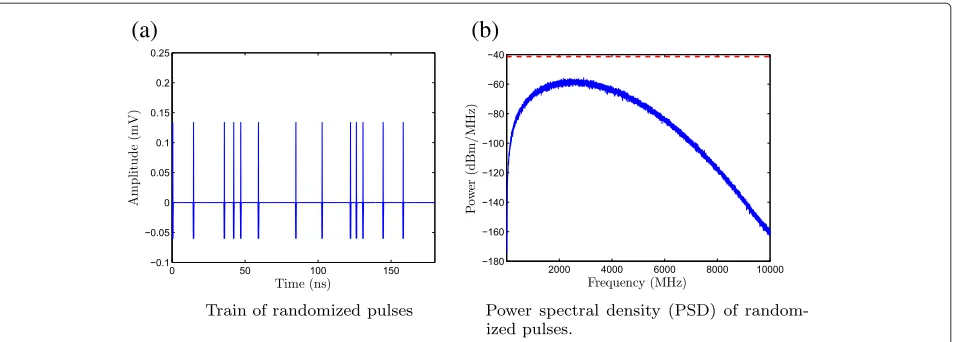
between pulses. The train of these pulses is shown in Figure 4a and its power spectrum is shown in Figure 4b. For this kind of signaling on average, the pulse rate will be close to 1/TSand the power spectrum will be smooth, as shown in Figure 4b (TS=18 ns, T=1 ns).
As discussed in Section 4, it is not possible from the hardware perspective to generate arbitrarily close pulses. Also, from the detector perspective it is not possible to resolve the timing between arbitrarily close pulses. For example, in the hardware architecture proposed in [18], the step recovery diode used in the transmitter has a fixed recovery time, preventing the generation of close pulses; and TDC used in the detector has a fixed time resolu-tion, preventing the detection of close pulses. One way to design the signaling is to have γn in (6) equal to the minimum separation needed between the pulsesTms, and modulation indexin (6) equal to the detectors sensitiv-ity (TDC time resolution). Thus, the resulting transmitted signal assuming 1 symbol per pulse is given by
Wtr(t)=
n
p(t−nTS−dn−Tms) (9) Figure 5 shows the illustration of this signaling. Each symbol has a fixed gap ofTmsin the beginning between [0,Tms] and the modulated RF pulse in the intervalM between(Tms,TS]. If log2Mis the modulation order, then the symbol timeTSand bitrateRbis given by
TS=Tms+M (10) and
Rb= log2M
TS
(a)
(b)
Figure 4Train of pulses with randomized pulse interval and its PSD.(a)TS=18 ns is employed and 1,000 pulses are considered for computing PSD.Dashed linein(b)indicates−41.3 dBm/MHz.
For any UWB hardware, the Tms and are fixed;
they come from the two UWB hardware constraints
discussed above. The modulation parameter M can be
picked to maximize the bitrate. To do this, (11) is
eval-uated and the optimal M that maximizes the bitrate
Rb is chosen. The variation of Rb versus M for
var-ious ratio’s of Tms/ (indicating different transceiver
hardware) is shown in Figure 6a. The bitrate Rb for
the optimal choice of M versus Tms/ is shown in
Figure 6b.
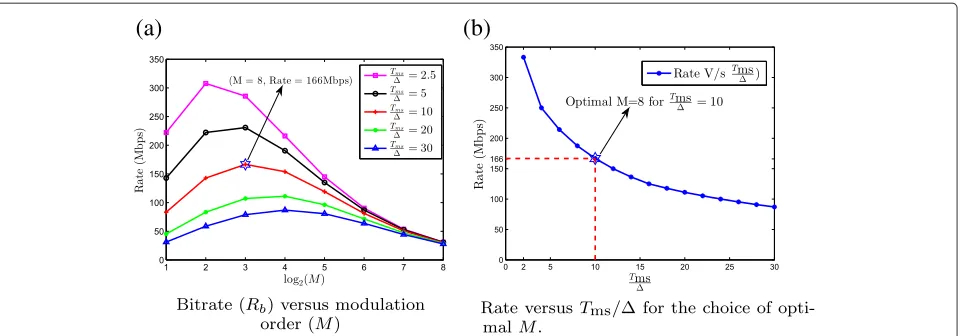
The bitrate peak to around 160 Mbps atM=8 when the
typical parameter values ofTms = 10 ns and = 1 ns
for the in-house UWB platform is considered.
The modulator algorithm which modulates the input symbol vector,d, is shown in Algorithm 1. The algorithm is initialized withXandY, denoting the TDC resolution and diode recovery time [18,39]. The method generateRF-Pulse in line 6 of the algorithm is used to generate the train of RF pulses as shown in (9). In the in-house pro-totype UWB platform, this is accomplished by generating
a trigger control signal from FPGA to the step recovery diode in transmitter [18]. Since no memory is employed between symbols in this signaling, it is called no-memory signaling. This modulator was introduced and briefly described in [38]. A variant of the M-PPM signal shown in
(9) withTms = 10 ns and modulation index= 1 ns is
generated. Five pulses of this are shown in Figure 7a. Each
symbol duration,TS=18 ns, resulting in PRF 1 MHz
causing only average power constraint being active. Each symbol constitutes a fixed constant gap ofTms = 10 ns, and 3 bits of information are modulated in the remaining
M=8 ns (since=1 ns,M=8). We cannot achieve
a smooth PSD as in Figure 4b because now, pulse train has deterministic gaps between pulses (Tms) and the pulse positions are quantized () for it to work with the chosen UWB hardware; however, the data can be assumed to be random because of interleaving and randomization in the symbol rate chain of the physical layer; this does smoothen the PSD. The PSD of this signaling scheme is shown in Figure 7b.
Figure 5Signaling employed to ensure minimum separation needed between pulses.Signal employed to haveγnin (6) equal to the
(a)
(b)
Figure 6Variation of bitrateRbwith parametersMandTms/.Choice of optimalM, where bitrate peaks depends onTms/. Bitrate peaks at M=8 for the nominal parameter values for the in-house hardware consisting ofTms=10 ns and=1 ns.
Algorithm 1No-memory signaling for UWB modulator
1: procedureNOMEMORYMODUL ATOR(d)
2: =X Initialize to TDC resolution
3: Tms=Y Initialize to diode recovery time 4: n←1
5: whilen≤Length(d)do
6: generateRFpulse(n,dn,Tms,)
7: Generate pulse p(t−nTS−dn−Tms)
8: n←n+1
9: end while
10: end procedure
The signaling employed above has a fixed gap,Tms in every symbol, as given in (9). This ensures that minimum separation between pulses is greater than or equal to the recovery time of the diode. If the modulator structure is
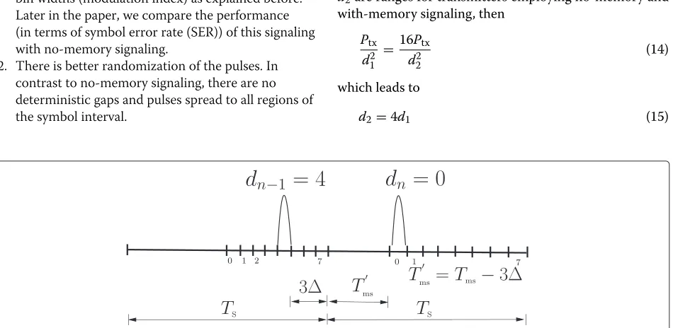
altered to remember the position of the transmitted pulse for the previous symbol, then the minimum gap needed for the current symbol can be reduced. We define this reduced gap asTms and it is illustrated in Figure 8. In Figure 8, gapTms is reduced by 3by remembering the position of the pulse in the previous symbol. The total separation between the pulses isTms = Tms +3. Since the duration of the symbol is constant, the reduction in the gap,Tms will result in an increased region for modu-lated RF pulses; this increases the time interval bin widths (modulation index), thereby increasing the detectability. Figure 8 shows the increase in bin widths for the second symbol (dn = 0) as gap, Tms reduced by 3. Since in this method the transmitter needs to remember the past transmitted symbol to decide theTms for the current sym-bol, we call this signaling as with-memory signaling. The algorithm for implementing this modulator is shown in Algorithm 2. It is initialized withXandY, denoting the
(a)
(b)
TDC resolution, , and diode recovery time, Tms. The algorithm takes a vector of symbols, d, and calls gener-ateRFPulse with different bin widthsn and gapTms to generate the train of RF pulses defined in (9).
Algorithm 2With-memory signaling for UWB modulator procedureWITHMEMORYMODUL ATOR(d)
2: 1=X Initialize to TDC resolution
Tms =Tms=Y Initialize to diode recovery time 4: n←2
generateRFpulse(1,d1,Tms,)
6: Generate pulse p(t−TS−d11−Tms ). whilen≤Length(d)do
8: Tms ←Tms−((M−1)−dn−1)n−1 ifTms <0then
10: Tms ←0
end if 12: n← Ts−T
ms M
generateRFpulse(n,dn,Tms ,n)
14: Generate pulse p(t−nTS−dnn−Tms ).
n←n+1
16: end while
end procedure
The two primary benefits of this signaling are summa-rized below.
1. There is better detectability due to an increase in the bin widths (modulation index) as explained before. Later in the paper, we compare the performance (in terms of symbol error rate (SER)) of this signaling with no-memory signaling.
2. There is better randomization of the pulses. In contrast to no-memory signaling, there are no deterministic gaps and pulses spread to all regions of the symbol interval.
The impact of 2) is further smoothing of the PSD; Figure 9a shows five symbols in the time domain, and Figure 9b shows the PSD with the modified signaling of
randomly generated 1,000 bits. The order M is chosen
as 8, recovery timeTms = 10 ns, and modulation index =1 ns as discussed above.
Comparing Figure 9b and Figure 7b indicates that with-memory signaling will smoothen the PSD more than the no-memory signaling. This will enable the transmitter to generate pulses at a higher amplitude without violating the mask specification of the regulatory bodies, thereby increasing the range. Comparing Figure 9a and Figure 7a indicates that the pulse amplitude can be increased by approximately 4 times compared to the no-memory sig-naling, without violating the regulatory body specifica-tions and with the same hardware constraints. For the deterministic single-path propagation model, the path loss, PL, is given by
PL= (4πdf) 2
c (12)
wheref is the frequency of operation,dis the range, and
cis the speed of light [40]. The received power, Prx, for transmitted power,Ptx, is given by (13).
Prx=
Ptx
PL (13)
An amplitude increase of 4 times results in 16 times (12 dB) increase in power. Since path loss is proportional to the square of the distance as given by (12), for any given received power and frequency of operation, ifd1and
d2are ranges for transmitters employing no-memory and with-memory signaling, then
Ptx
d12 =
16Ptx
d22 (14)
which leads to
d2=4d1 (15)
(a)
(b)
Figure 9With-memory signaling and its PSD withM=8,=1 ns andTms/=10.For computing PSD, 1,000 pulses are considered. The dashed vertical linein(a)indicates the symbol boundary, and thedashed horizontal linein(b)indicates−41.3 dBm/MHz, average power constraint defined by the FCC for in-house UWB radio operating at 6 GHz.
Eq. 15 means that the range can be increased by 4 times compared to the no-memory signaling. This increased range comes with a cost of increased complexity in the modulator, as shown in Algorithm 2.
In the next section, we will evaluate the performance of the demodulator for the proposed signaling scheme.
6 Detector performance
In this section, we propose a detector for the modula-tors proposed before and evaluate its performance. For analytical discussion, we assume that the symbol tim-ing acquisition procedure has been performed prior to data transmission. For the no-memory signaling modula-tor withM=8, a hard decision demodulator is designed. The demodulator uses the quantized 8 time interval bins as defined in Table 1. This is also illustrated in Figure 10.
The intervals for two corner bins are larger because the detector can exploit the dead timeTmsleft for the diode recovery. The algorithm for the hard decision demodula-tion is shown in Algorithm 3. The algorithm demodulates the received vector,r, into a vectorDemodulatedSymbol. The PeakPosition in line 3 of the algorithm returns the peak position of the received pulse.
The performance bounds for the no-memory signaling are derived in terms of SER. The received signal is as defined in (7). For no-memory signaling transmitter, the
Table 1 Time intervals used for hard decision demodulation
Quantized time intervals for hard decision demodulation ∇0
Tms
2
−Tms
2 +
∇i [(i−((i+1))] fori∈[1, .., 6]
∇7
Tms
2 +6
−TS+Tms2
received signal at the receiver will haveγn = Tmsand is given by
Wrx(t)=Er
n
pt−nTS−dn−Tms−j(n) +n(t) (16)
Algorithm 3Hard decision demodulation for no-memory signaling
procedureHARDDECISION(r) forj=1→Length(r)do
3: ∇ ←PeakPosition(rj)
Find the position of the peak for symbol j
if∇ ∈ ∇i,i∈[0, .., 7]then
6: ∇is are defined in Table 1
DemodulatedSymbolj←i
end if
9: end for
end procedure
As shown in Table 1, from the detector perspective, there are three different types of symbols. The first sym-bol 0 and the last symsym-bol 7 have a much larger detection probability, since their decision interval (∇0,∇7) is large.
The middle symbols [1−6] have the same and smaller
decision intervals ∇i = ,i ∈ [1, 6]. In general, if the modulation order isM, and all symbols are equally likely, then the corner symbols will occur each with a probability of 1/Mand middle symbols with(M−2)/M. IfPe1is the probability of a symbol error for the middle symbol, and
Figure 10Quantized time bins used by the hard decision detector.The corner bins are wider than the middle bins.
Refer Table 1 and Figure 10.
Pe=
When the signal referred in (16) is passed through a peak detector, the combined effect of the jitterj(n)and noisen(t)on the peak detector will cause an error in the peak position. This error in the peak position w(n)can be assumed to be Gaussian distributed with mean 0 and varianceσ2, Therefore, we get
Pr
Q-function is the tail probability of the standard normal distribution. The parameterβis the ratio of bin width to standard deviationσ of the random errors in the peak position. Similarly,
Here in the third equality, transceiver specific ratio (Tms/) = α is assumed. Substituting (18) and (19) in (17), the symbol error probabilityPeas given by
Pe=2
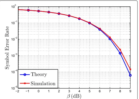
The performance is evaluated in simulations with
M=8,=1 ns, andTms=10 ns(α=10). The simula-tion consisted of of 200,000 randomly generated symbols. The symbol error rate for variousβ values are shown in Figure 11. A strong correlation forPebetween theory and simulation is observed.
Earlier, we proposed a modified signaling with memory in the modulator (with-memory signaling), which claimed to have two benefits.
1. A better detectability due to an increase in the bin widths (modulation index), as explained before. 2. Better randomization of the pulses. Unlike in the
no-memory signaling, there are no deterministic gaps and pulses are spread to all regions of the symbol interval.
The impact of 2) is further smoothing of the PSD, which is demonstrated earlier with the PSD plots. To quan-tify the performance improvement due to 1), detector performance of with-memory signaling and no-memory signaling needs to be compared. We implemented a hard decision detection algorithm for the with-memory signaling. This algorithm is described in Algorithm 4. The algorithm demodulates the received vector, r, into
a vectorDemodulatedSymbol. ParametersTms andTS
in the algorithm should be the same as those used in the with-memory modulator algorithm defined in Algorithm 2. The PeakPosition in line 4 of the algo-rithm returns the peak position of the received pulse. This algorithm is similar to the no-memory demod-ulator defined in Algorithm 3, except that the bin
width i changes between symbols, and it depends
on the previous bin width and previously decoded symbol.
It is not straightforward to obtain a closed-form ana-lytical expression for the performance of with-memory signaling. In with-memory signaling on average Tms < Tms, if we assume that all the symbols are equally likely, then the average symbol value (∈[0,M−1]) for the pre-vious symbol is(M−1)/2; therefore, on averageTms is given by
Tms =Tms−(
M−1)
2 (21)
The average bin width for with-memory signaling is given by
= TS−Tms
M (22)
= Tms−Tms +M
M (23)
where we in the second equality used (10). Further apply-ing (21) to (23), we get
=
3M−1
2M
(24)
If we defineβas the ratio of/σ, then we have
β=3M−1
2M
β (25)
Algorithm 4Hard decision demodulation for with-memory signaling procedureHARDDECISIONDEMOD(r)
Demodulate the 1st symbol
← TS−Tms M
4: ∇ =PeakPosition(r[1]) if∇ ∈ ∇i i∈0, ..7then
DemodulatedSymbol[1]←i
∇is are defined in Table 1
8: end if
forj=2→Length(r)do
Tms =Tms−
(M−1)−DemodulatedSymbolj−1
← TS−Tms M
12: ∇ =PeakPositionrj
if∇ ∈ ∇i i∈0, ..7then
∇is are defined in Table 1 Newcomputed above is used
16: DemodulatedSymbolj←i
Substituting (25) in (20), we get the symbol error prob-ability for the with-memory signaling and is given by (26). in better detectability of symbols at the receiver. In sim-ulation, it was observed that the bin width increases by =1.32. This reduction in the bin width is due to line
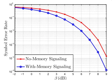
9 - 12 in the modulator Algorithm 2, where in order to ensure one pulse per symbol period,Tms is forced to zero, resulting in the reduction of bin width for the transmitted symbol. The performance of detector for with-memory signaling is evaluated in simulation with 200,000 ran-domly generated samples, and the results are compared with no-memory signaling. Figure 12 compares the per-formance of the hard decision detectors for no-memory and with-memory signaling schemes. A gain of approxi-mately 1 dB can be achieved in terms of SNR at a symbol error rate of 10−2by using with-memory signaling.
The presented symbol error rate (SER) performance for the proposed signaling schemes are valid for the transceivers which are in line of sight (LOS) with short dis-tance between them and having highly directional anten-nas as discussed in Section 2. For these systems, we can assume a simple AWGN channel model. However, for systems having fading channels with multi-path, channel equalization and time of arrival (TOA) estimation needs to be performed prior to demodulation. The SER perfor-mance of the proposed signaling schemes in such systems depends on the performance of channel equalization and TOA estimation algorithms.
Figure 12Comparison of performance of no-memory and with-memory signaling in terms of symbol error rate.
7 Conclusion
In this paper, we proposed a custom signaling which is a variant of PPM signaling for IR-UWB communication. We also proposed an alternative signaling called with-memory signaling, which requires with-memory in the mod-ulator and demodmod-ulator, however, can further smoothen PSD compared to no-memory signaling. The result of this is illustrated in Figure 9b. We showed that range can be increased by 4 times compared to no-memory signaling, without violating the regulatory body con-straints. This gain comes with a cost of increased com-plexity in the modulator and demodulator, as discussed in the modulator and demodulator Algorithms 2 and 4 for with-memory signaling. We also derived the theoret-ical closed-form expression for a hard decision demod-ulator with no-memory signaling. We compared the performance with the derived theoretical result; this is illustrated in Figure 11. We implemented a detec-tor for the with-memory signaling proposed in this paper. The detector performance of with-memory sig-naling is compared with the detector performance for no-memory signaling. We showed that with-memory sig-naling can improve the detector performance by approx-imately 1 dB at 10−2 SER. Results are illustrated in Figure 12.
Competing interests
The authors declare that they have no competing interests.
Acknowledgements
Parts of the work have been funded by The Swedish Agency for Innovation Systems (VINNOVA).
Author details
1Department of Signal Processing, KTH Royal Institute of Technology, Fack,
100 44 Stockholm, Sweden.2Engineering Department, University of Perugia,
Perugia, Italy.
Received: 25 June 2014 Accepted: 23 September 2014 Published: 3 October 2014
References
1. MGD Benedetto, T Kaiser, AF Molisch, I Oppermann, C Politano, D Porcino, Ultra-wideband Communication Systems: A Comprehensive Overview. (Hindawi Publishing Corporation, New York, 2006)
2. H Nikookar, R Prasad,Introduction to Ultra Wideband for Wireless Communications.Signals and Communication Technology Series. (Springer, London, 2009). http://books.google.se/books?id=6ico-tJpmcYC 3. Federal Communications Commission, Revision of part 15 of the
commision’s rules regarding ultra-wideband transmission systems. First report and order. Technical report, FCC, Washington DC, ET Docket 98-153 (2002)
4. R Hoctor, H Tomlinson, Delay-hopped transmitted-reference RF communications, inUltra Wideband Systems and Technologies, 2002. Digest of Papers. 2002 IEEE Conference On(2002), p. 265–269.
doi:10.1109/UWBST.2002.1006368
5. AM Orndorff, Transceiver Design for Ultra-Wideband Communications, Electrical and Computer Engineering. Virginia Polytechnic Institute and State University (2004)
6. H Luecken, Communication and Localization in UWB Sensor Networks. PhD thesis, ETH ZURICH (2012)
7. J Zhang, PV Orlik, Z Sahinoglu, AF Molisch, P Kinney, UWB Systems for Wireless Sensor Networks. Proc. IEEE.97(2), 313–331 (2009). doi:10.1109/JPROC.2008.2008786
8. AF Molisch, Ultrawideband propagation channels-theory, measurement, and modeling. IEEE Trans. Veh. Tech.54(5), 1528–1545 (2005). doi:10.1109/TVT.2005.856194
9. L-L Yang, L Hanzo, Residue number system assisted fast frequency-hopped synchronous ultra-wideband spread-spectrum multiple-access: a design alternative to impulse radio. IEEE J. Sel. Area. Comm.20(9), 1652–1663 (2002). doi:10.1109/JSAC.2002.805059 10. A Batra, J Balakrishnan, AG Dabak, R Gharpurey, P Fontaine, H Lin, U.S.
Patent 20040151109 A1, 5 Aug 2004
11. R Fisher, R Kohno, H Ogawa, H Zhang, K Takizawa, M Mc Laughlin, M Welborn, DS-UWB Physical Layer Submission. 802.15 task group 3a. IEEE P, Los Alamitos (2005), 15–40
12. MZ Win, RA Scholtz, Ultra-wide bandwidth time-hopping spread-spectrum impulse radio for wireless multiple-access communications. IEEE Trans. Commun.48(4), 679–689 (2000). doi:10.1109/26.843135 13. RA Scholtz, Multiple access with time-hopping impulse modulation, in
Military Communications Conference, 1993. MILCOM ‘93. Conference Record. Communications on the Move., IEEE,vol. 2, (1993), p. 447–4502.
doi:10.1109/MILCOM.1993.408628
14. MZ Win, RA Scholtz, Impulse radio: how it works. IEEE Comm. Lett. 2(2), 36–38 (1998). doi:10.1109/4234.660796
15. A De Angelis, M Dionigi, R Giglietti, P Carbone, Experimental comparison of low-cost sub-nanosecond pulse generators. IEEE Trans. Instrum. Meas. 60(1), 310–318 (2011). doi:10.1109/TIM.2010.2047591
16. A De Angelis, M Dionigi, A Moschitta, R Giglietti, P Carbone, Characterization and modeling of an experimental UWB, pulse-based distance measurement system. IEEE Trans. Instrum. Meas.
58(5), 1479–1486 (2009). doi:10.1109/TIM.2008.2009204 17. D Strömberg, A De Angelis, P Händel, A low-complexity
adaptive-threshold detector for pulse UWB systems, inInt. Workshop ADC Modelling, Testing Data Converter Analysis Design/IEEE, (2011), p. 294–299
18. A De Angelis, S Dwivedi, P Handel, Characterization of a flexible UWB sensor for indoor localization. IEEE Trans. Instrum. Meas.62(5), 905–913 (2013). doi:10.1109/TIM.2013.2243501
19. Broadband omnidirectional antenna - Elite-2460, [online]. Available: http://www.greenwavescientific.com/
20. Timedomain Company. http://www.timedomain.com/ 21. Ubisense Company. http://www.ubisense.net/ 22. Zebra Company. http://www.zebra.com/ 23. BeSpoon Company. http://www.bespoon.com/ 24. Decawave Company. http://www.decawave.com/
25. DW1000 - DecaWave’s precise indoor location and communication chip, [online]. Available: http://www.decawave.com/
26. Time Domain PulsON (P400) Ranging and Communications Module (RCM). [Online] Available:. http://www.timedomain.com
27. The Series 7000 Ubisense UWB sensors.[Online]. Available:. http://www. ubisense.net/
28. J Rantakokko, P Handel, M Fredholm, F Marsten-Eklöf, User requirements for localization and tracking technology: a survey of mission-specific needs and constraints, inIndoor Positioning and Indoor Navigation (IPIN), 2010 International Conference On(2010), p. 1–9.
doi:10.1109/IPIN.2010.5646765
29. S Gezici, Z Tian, GB Giannakis, H Kobayashi, AF Molisch, HV Poor, Z Sahinoglu, Localization via ultra-wideband radios: a look at positioning aspects for future sensor networks. IEEE Signal Process. Mag.22(4), 70–84 (2005). doi:10.1109/MSP.2005.1458289
30. M Ghavami, LB Michael, S Haruyama, R Kohno, A novel UWB pulse shape modulation system. Wireless Pers. Comm.23, 105–120 (2002). 10.1023/A:1020953424161
31. M Ghavami, LB Michael, R Kohno,Ultra Wideband Signals and Systems in Communication Engineering. (John Wiley, West Sussex, 2007)
32. K Witrisal, G Leus, G Janssen, M Pausini, F Troesch, T Zasowski, J Romme, Noncoherent ultra-wideband systems. IEEE Signal Process. Mag.26(4), 48–66 (2009). doi:10.1109/MSP.2009.932617
33. I Guvenc, H Arslan, Performance evaluation of UWB systems in the presence of timing jitter, inUltra Wideband Systems and Technologies, 2003 IEEE Conference On, (2003), p. 136–141. doi:10.1109/UWBST.2003.1267818 34. S Gezici, AF Molisch, HV Poor, H Kobayashi, The tradeoff between
processing gains of an impulse radio UWB, system in the presence of timing jitter. IEEE Trans. Commun.55(8), 1504–1515 (2007). doi:10.1109/TCOMM.2007.902536
35. H Wymeersch, J Lien, MZ Win, Cooperative localization in wireless networks. Proc. IEEE.97(2), 427–450 (2009).
doi:10.1109/JPROC.2008.2008853
36. F Troesch, F Althaus, A Wittneben, Pulse position precoding exploiting UWB power constraints, inSignal Processing Advances in Wireless Communications, 2005 IEEE 6th Workshop On, (2005), p. 395–399. doi:10.1109/SPAWC.2005.1506054
37. H Khani, H Nie, W Xiang, Z Xu, Z Chen, Low complexity suboptimal monobit receiver for transmitted-reference impulse radio UWB systems, inGlobal Communications Conference (GLOBECOM), 2012 IEEE, (2012), p. 4084–4089. doi:10.1109/GLOCOM.2012.6503756
38. V Yajnanarayana, S Dwivedi, A De Angelis, P Handel, Design of impulse radio UWB transmitter for short range communications using PPM signals, inElectronics, Computing and Communication Technologies (CONECCT), 2013 IEEE International Conference On, (2013), p. 1–4. doi:10.1109/CONECCT.2013.6469303
39. A Zhu, F Sheng, A Zhang, An implementation of step recovery diode-based UWB pulse generator, inUltra-Wideband (ICUWB), 2010 IEEE International Conference On,vol. 2, (2010), p. 1–4.
doi:10.1109/ICUWB.2010.5614726
40. M Skolnik,Radar Handbook, Third Edition.Electronics electrical engineering. (McGraw-Hill Education, New York, 2008). http://books. google.se/books?id=76uF2Xebm-gC
41. J-O Nilsson, D Zachariah, I Skog, P Händel, Cooperative localization by dual foot-mounted inertial sensors and inter-agent ranging. EURASIP J. Adv. Signal Process.2013(164) (2013). doi:0.1186/1687-6180-2013-164
doi:10.1186/1687-1499-2014-158