Article 1
Pendulum-type hetero-core fiber optic accelerometer
2for low-frequency vibration monitoring
3Hiroshi Yamazaki 1,*, Ichiro Kurose 1, Michiko Nishiyama 2, and Kazuhiro Watanabe 2 4
1 Department of Information Systems Science, Faculty of Science and Engineering, SOKA university, 1-236 5
Tangi-machi, Hachioji, Tokyo 192-8577, Japan
6
2 Department of Science and Engineering for Sustainable Innovation, Faculty of Science and Engineering, 7
SOKA university, 1-236 Tangi-machi, Hachioji, Tokyo 192-8577, Japan; {mnishiya, kazuhiro}@soka.ac.jp
8
* Correspondence: [email protected]; Tel.: +81-042-691-9400
9
10
Abstract: In this paper, a novel pendulum-type accelerometer based on hetero-core fiber optics has 11
been proposed for structural health monitoring targeting large-scale civil infrastructures. Vibration 12
measurement is a non-destructive method for diagnosing the failure of structures by assessing 13
natural frequencies and other vibration patterns. The hetero-core fiber optic sensor utilized in the 14
proposed accelerometer can serve as a displacement sensor with robustness to temperature changes 15
in addition to immunity to electromagnetic interference and chemical corrosions. Thus the hetero-16
core sensor inside the accelerometer measures applied acceleration by detecting the rotation of an 17
internal pendulum. A series of experiments showed that the hetero-core fiber sensor linearly 18
responded to the rotation angle of the pendulum ranging within ±5°, and furthermore the proposed 19
accelerometer could reproduce the waveform of input vibration in a frequency band of several Hz 20
order. 21
Keywords: structural health monitoring; fiber optic sensor; accelerometer; hetero-core; low-22
frequency vibration measurement 23
24
1. Introduction 25
For preventing serious disasters caused by civil infrastructures collapsed, the existence of 26
structural damage and any other faults in infrastructures have to be early and accurately detected, in 27
spite of uncountable infrastructures and the inadequate number of inspectors. The process of 28
implementing fault diagnosis strategy is referred to as structural health monitoring (SHM), in which 29
the failure in a structure is automatically observed by monitoring, data processing, and health 30
evaluation systems [1]. 31
As one of SHM techniques, fault diagnosis based on vibration monitoring was widely known as 32
a non-destructive sensing and analysis scheme for global fault diagnosis and has been studied so far 33
in the literature [2-5]. Typically, a decrease in stiffness of the structure is observed in a natural 34
frequency getting lower than expected value. In contrast, the frequency higher than expected implies 35
that the structure was supported stiffer than expected. 36
There have been a lot of studies researched for analyzing the faults in infrastructures from 37
vibration information. For instance, Soman et al. employed several stiffness indices based on modal 38
frequency, displacement and strain for quantifying the degree of structural health by use of a multi-39
metric measurement system [6]. Moreover, a practical non-destructive bridge condition assessment 40
was also examined on an actual bridge using accelerometers in combination with cable tension 41
sensors, anemometers and thermistors [7]. However, when considering practical usages in actual 42
infrastructures, the SHM system should be robust to ambient noise, temperature changes and 43
corrosions in harsh measurement environments [8]. 44
With the development of vibration monitoring methodology, a number of sensing devices have 45
also been proposed aiming at SHM based on electric-based sensors based on piezoelectric, capacitive, 46
and [9-13]. However, it is necessary for the sensor devices to be highly robust to electromagnetic 47
interference and severe temperature changes in order to monitor civil infrastructures for long term 48
in harsh environments, which is always exposed to changes in weather, or sometimes water leakage 49
and lightning damages. In comparison, fiber optic sensors were known as an alternative sensing 50
technology to electric sensors for SHM because of their remarkable merits. Fiber optic sensors are 51
non-electrical and passive devices, immune to electromagnetic interference and chemical corrosions, 52
and have the ability of remote sensing, thereby those of which makes them suited to outdoor long-53
term smart sensing [14]. 54
There have been a variety of fiber optic sensors developed for smart structures by use of Brillouin 55
scattering [15, 16], fiber Bragg grating (FBG) [17-24], and optical interferometer [25, 26]. Minardo et 56
al. introduced distributed fiber optic temperature and strain sensors using Brillouin optical time-57
domain analysis (BOTDA) into railway infrastructures and succeeded to dynamically monitor strain 58
distribution due to train passage [15]. Moreover, a considerable number of fiber Bragg grating (FBG) 59
sensors have also been proposed for detecting strain in structure by embedding sensors themselves 60
[17-19], and they can perform as accelerometers by means of sensing the deformation of on an 61
oscillated cantilever beam [20-22]. A fiber optic accelerometer based on Fabry-Perot interference were 62
also investigated [25]. This accelerometer detects vibration in a range up to some hundreds Hz in 63
such a way to measure the flexure of an optical fiber cantilever beam by Fabry-Perot interference. 64
In this paper, we have proposed a novel accelerometer based on a hetero-core fiber optic sensor 65
for natural vibration monitoring on large-scale infrastructures. Hetero-core fiber optic sensors consist 66
of two single-mode fibers fusion-spliced with different core diameters to obtain high sensitivity to 67
macro-bending on the processed fiber line [27]. Compared to conventional fiber optic sensors, the 68
hetero-core fiber sensors have some attractive features such as a cost-effective measurement scheme 69
by use of a light emitting diode (LED) and a photo diode (PD), and temperature independency on 70
sensor responses [28]. 71
The scope of this study is to realize a pendulum-type accelerometer targeting low-frequency 72
natural vibration on large-scale infrastructures, in which an embedded hetero-core sensor detects the 73
rotation position of an internal pendulum. The movement of the pendulum was subjected to a 74
combination of a weight and springs equipped with the pendulum so that they dominantly 75
determined the resonance characteristics of the proposed accelerometer. On the other hand, it was so 76
far demonstrated that the hetero-core sensor was able to measure displacement with high linearity 77
by a conversion mechanism to transform displacement to macro-bending [29], thereby the rotation 78
of pendulum can be detected in such a way that the hetero-core optical fiber measured the 79
displacement on a given point on the pendulum. A series of experiments were conducted to confirm 80
that the hetero-core optical fiber inside the accelerometer measures the rotation of internal pendulum 81
with a good linearity. In addition, it was revealed that the accelerometer performed well in low-82
frequency vibration measurement by tuning the sensitivity and frequency response characteristics 83
depending on dynamic parameters of the pendulum. 84
2. Sensor principle 85
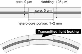
As shown in Figure 1, a hetero-core fiber optic sensor proposed in this paper is composed of a 86
short single mode (SM) fiber segment called a hetero-core portion, inserted by fusion splicing into an 87
SM fiber transmission line. The core diameters of the hetero-core portion and the transmission line 88
are 5 μm and 9 μm, respectively, and the length of the hetero-core portion is about 1-2 mm. It was 89
previously confirmed that light transmitted through the core partially leaks into a cladding layer at 90
a boundary between the transmission fiber and the hetero-core portion, and the degree of light 91
Figure 1. Schematics of a hetero-core fiber optic sensor.
93
A displacement sensor based on hetero-core fiber optics has already been reported [29] by 94
employing the conversion mechanism from displacement to bending, as illustrated in Figure 2(a). 95
The hetero-core optical fiber is clamped across the hetero-core portion by a pair of fiber clampers, one 96
of which is set to move and the other is fixed. When the displacement of the clampers d increases, the 97
optical loss of the sensor was linearly increased as the increment of bending radius on the hetero-core 98
portion, as shown in Figure 2(b). The accuracy of the sensor to the displacement was less than 0.1 99
%FS so that the hetero-core fiber optic sensor can be employed as a highly-accurate displacement 100
sensor. 101
102
Figure 2. Sensing principle of a hetero-core fiber optic displacement sensor: (a) experimental setup
103
and (b) optical loss response to applied displacement.
104
Figure 3. (a) Appearance and (b) schematics of a pendulum-type accelerometer with a hetero-core
105
fiber optic sensor.
106
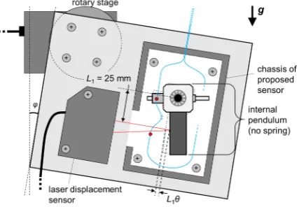
Figure 3 illustrates a schematic drawing of the proposed pendulum-type accelerometer based 107
on hetero-core fiber optics. As shown in Figure 3(a), an internal pendulum built in the accelerometer 108
optical fiber is clamped at two points, one of which is on the pendulum and the other is fixed on the 110
chassis, thereby the sensor detects the rotation angle of the pendulum as a displacement of the 111
clamped point on the pendulum. When a whole system of the accelerometer was accelerated, the 112
internal pendulum rotates due to an inertial force and makes the position of the clamped point of the 113
hetero-core fiber displaced. Figure 3(b) shows the simplified vibration model of the proposed 114
accelerometer, in which it is supposed that the weight of pendulum exists at a centroid of weight (far 115
from the rotation shaft by L1 = 25 mm) and is physically subjected to two springs. The effective mass 116
of the weight meff is determined from the mass of the weight m, those of other components mi, and 117
the distance of components from the rotation shaft li by moment equation as follows: 118
= + ∑ , (1)
In addition, the effective elastic coefficient keff is also expressed from k, the elastic coefficient of 119
two employed springs as follows: 120
= 2 , (2)
in which lspr denotes the distance of the springs from the rotation shaft. Therefore, when the 121
pendulum is rotated by input acceleration α(t), the equation of motion in the pendulum is described 122
as follows: 123
+ + = ( ), (3)
where θ denotes a rotation angle of the pendulum and λ represents a damping factor of the system 124
including friction around the rotation shaft. From this equation, the resonant frequency of this 125
vibration system f0 can be derived as follows: 126
= . (4)
Furthermore, when the frequency of input vibration α(t) is sufficiently lower than the resonant 127
frequency, the following relational expression holds for α and θ because of the first and second terms 128
in the right side of Eq. (3) can be neglected. 129
= = ( ) . (5)
On the other hand, the hetero-core fiber optic sensor detects the rotation as the displacement 130
L2θ, when θ is sufficiently small. The relation between the rotation angle θ and an optical loss of the 131
hetero-core sensor is described as follows, on the condition that the sensor linearly responds to the 132
displacement: 133
= L = , (6)
in which the coefficient γ means the ratio of optical loss response to the rotation angle. Therefore, 134
considering Eq. (5) and (6), the sensitivity of the accelerometer can be obtained by the following 135
formula: 136
= ( ) . (7)
It can be seen from Eq. (7) that the sensitivity has trade-off relation to the resonant frequency 137
which determines the width of a measurable frequency band, a combination of a weight and springs 138
should be modulated in balance for measuring low-frequency natural vibration in infrastructures 139
with high sensitivity. 140
3. Static rotation response 141
For evaluating the sensitivity and linearity of a hetero-core fiber optic sensor to the rotation of 142
pendulum, a static rotation test was conducted, in which the relation between a rotation angle of the 143
accelerometer and a laser displacement sensor measuring the centroid position of the pendulum were 145
fixed on a firm plate rotated by a rotary stage. The rotary stage got the plate slowly inclined by φ in 146
the range of ±8° with a stepwise of 0.5°, and the optical loss and the displacement of weight were 147
simultaneously recorded. In this experiment, two springs inside the accelerometer were removed in 148
advance in order to reduce the difference between the inclination angle φ and the internal rotation 149
angle of pendulum θ. Furthermore, the displacement of weight measured by the laser displacement 150
sensor was regarded as L1θ because the rotation angle θ would be sufficiently small. 151
152
Figure 4. Experimental setup for hetero-core fiber sensitivity to the rotation of a pendulum in the
153
inclined accelerometer.
154
Figure 5(a) shows the variation of optical loss as a function of the rotation angle of weight θ 155
measured by the laser displacement sensor. It can be seen that the optical loss linearly changed with 156
a sensitivity of 0.0928 dB/° in the range -5° < θ < 5°. In spite of the linear response of a hetero-core 157
fiber optic sensor to the displacement as mentioned in section 2, nonlinear responses in ranges θ < -158
5° and θ > 5° would result from the change of an axial angle of the optical fiber at a fixed point on 159
the pendulum. In particular, when the pendulum rotated by θ < 0° as depicted in Fig. 5(b.1), θaxis, the 160
axial angle of the optical fiber at a fixed point on the pendulum, was also rotated as much as θ, which 161
made the curvature on the hetero-core portion higher than the case that the only displacement L2θ 162
was applied with θaxis = 0°. Similarly in the case θ > 0°, as shown in Fig. 5(b.2), the change of θaxis got 163
lower the increment of curvature on the hetero-core portion due to the applied displacement. 164
Although this phenomenon would always appear in this sensing mechanism, the effect on sensor 165
response appeared to be negligible in the small rotation angle so that the sensitivity of the hetero-166
core optical fiber to rotation angle γ is 0.0928 dB/° with a linearity in the range of -5° < θ < 5°. 167
168
Figure 5.(a) Optical loss variation of a hetero-core optical fiber inside a proposed accelerometer as
169
functions of angle of weight θ, and (b.1) (b.2) schematics of excess changes in the axial angle of the
170
4. Frequency response characteristics 172
To understand the optimum specification of the proposed accelerometer for monitoring low-173
frequency vibration, the frequency responses were monitored with arranging combinations of the 174
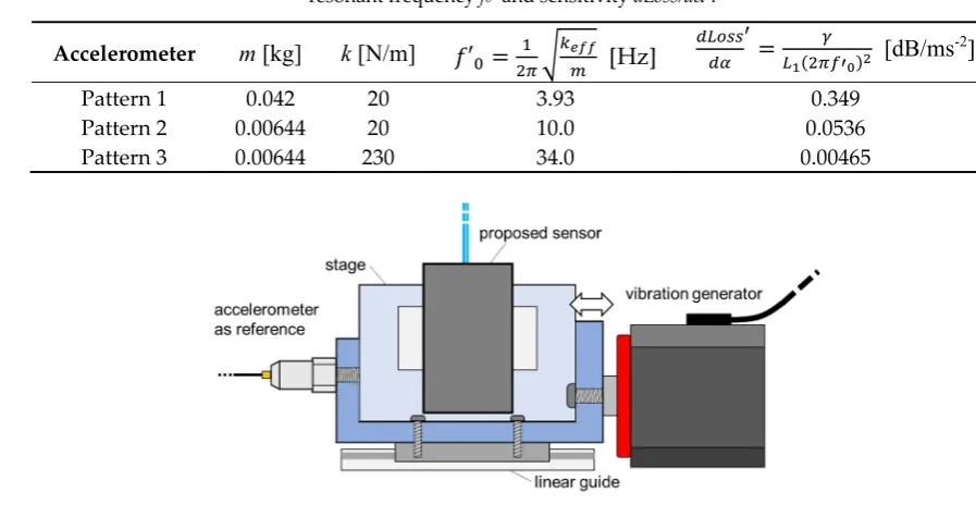
weight and springs as listed in table 1. The values of f0’ and dLoss/dα' were calculated as approximate 175
resonant frequencies and sensitivities without considering the effective masses of pendulum 176
components except for a weight. In this experiment, as illustrated in Figure 6, the proposed 177
accelerometer was attached together with an electric accelerometer used as a reference on a stage 178
which was horizontally vibrated by a vibration generator (WaveMaker01, asahi seisakusyo). The 179
waveform applied by the vibration generator was set to be sinusoidal with a frequency ranging from 180
1 Hz to 50 Hz, and the duration of each test was for 10 seconds in each frequency. During the test, 181
both input acceleration and output data by the reference and the proposed accelerometer were 182
simultaneously measured by a sampling rate of 4 kHz. 183
Table 1. The combinations m and k of the proposed accelerometer, and approximate values of
184
resonant frequency f0’ and sensitivity dLoss/dα’. 185
Accelerometer m [kg] k [N/m] ′ = [Hz] = ( ) [dB/ms
-2]
Pattern 1 0.042 20 3.93 0.349
Pattern 2 0.00644 20 10.0 0.0536
Pattern 3 0.00644 230 34.0 0.00465
186
Figure 6.Experimental setup for frequency response characteristics of the proposed accelerometer.
187
Figure 7 shows the frequency response of the proposed accelerometer, which was obtained as 188
an input-to-output ratio by comparing the amplitudes of the fast Fourier transform (FFT) spectra for 189
each frequency. It was observed that the resonant frequency f0 shifted with a tendency like f0’ 190
described in table 1, and the sensitivity decreased inversely to the resonant frequency. When 191
calculating dLoss/dαby obtained f0 according to Eq. (7), the values plotted as dashed lines in Fig. 7 192
were found to overlap with the measured in frequency bands lower than f0. In a case of Pattern 1, the 193
input-to-output ratio seems to gradually increase as the increment of frequency. In the other cases of 194
Patterns 2 and 3, however, the stable input-to-output ratios were observed in low-frequency bands 195
up to 4 Hz and up to 15 Hz, respectively. 196
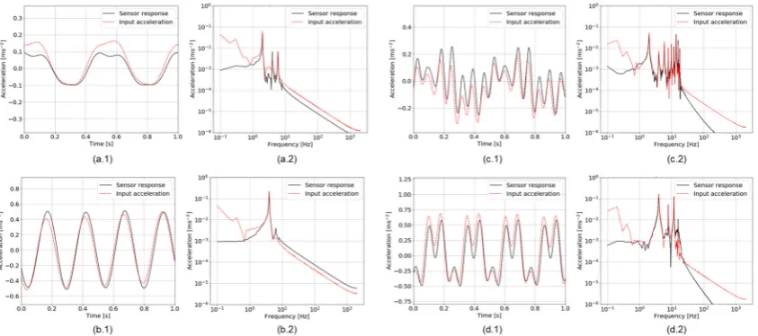
Additionally, Figure 8 shows profiles of sensor responses in cases of Patterns 2 and 3 when 2- 197
and 4-Hz vibrations were applied. In order not to take into consideration vibrations excited due to 198
resonance, high-frequency components were numerically removed by the finite impulse response 199
(FIR) low-pass filtering with a cut-off frequency of 0.8 × f0. In a case of Pattern 2, it can be seen in Figs. 200
8(a.1) and (b.1) that the proposed accelerometer responded to vibration with a negligible phase shift 201
comparing to input acceleration data measured by the reference sensor. Moreover, the frequency 202
spectra depicted in Figs. 8(a.2) and (b.2) indicated that the proposed accelerometer well reproduced 203
the frequency spectrum of input acceleration in the range from 1 Hz to the cut-off frequency. There 204
derived from unwanted harmonic components of input vibration generated by the vibration 206
generator. On the other hand, spectral components under 1 Hz tended to be lower in the sensor 207
response than in input vibration. It would be caused by that the proposed accelerometer had a 208
reduced sensitivity at around 1 Hz, which can be supposed in Fig. 7. These features in terms of a 209
phase shift and a spectral form in a frequency band ranging from 1 Hz to 0.8 × f0 Hz were similarly 210
observed in the case of Pattern 3 as shown in Figs. 8(c) and (d). As a result, it was confirmed that the 211
proposed accelerometer well performed with a stable sensitivity in a frequency band more than 1 Hz 212
and less than f0, with keeping the theoretical trade-off relation between the sensitivity and resonant 213
frequency. However, the lower resonant frequency of accelerometer was, the higher but the less 214
stable sensitivity was obtained. For such a reason, the accelerometer should be utilized with moderate 215
adjustments on the internal weight and springs such as in Patterns 2 and 3. 216
Figure 7.Frequency response characteristics of the proposed accelerometer which was modulated in
217
three patterns shown in table 1.
218
Figure 8. Profiles of responses of the proposed accelerometer and input vibration in (x.1) time domain
219
and (x.2) frequency domain: (a) 2-Hz vibration applied to the proposed accelerometer in pattern 2, (b)
220
4-Hz vibration to the accelerometer in pattern 2, (c) 2-Hz vibration to the accelerometer in pattern 3,
221
and (d) 4-Hz vibration to the accelerometer in pattern 3.
222
5. Conclusion 223
This paper described a novel pendulum-type accelerometer based on hetero-core fiber optics for 224
monitoring low-frequency natural vibrations in large-scale infrastructures such as bridges, building, 225
and tunnels. This accelerometer contained a pendulum with a weight and springs, whose rotation 226
motion in the system of pendulum, the rotation angle was proportional to applied acceleration in a 228
range under a resonant frequency. 229
Through a static rotation test, it was found that the hetero-core fiber sensor linearly responded 230
to the rotation angle in a range within ±5°, although it nonlinearly responded out of this range because 231
the rotation of a fixed point of a fiber line on the pendulum broke the linearity of the sensor response. 232
Moreover, the ratio of rotation angle to applied acceleration varied inversely with respect to the value 233
of resonant frequency f0, the sensitivity of the accelerometer was able to be calculated from f0 234
experimentally observed. Additionally, it was also confirmed that the accelerometer showed a stable 235
sensitivity and reproduced a waveform of input acceleration in a frequency band from 1 Hz to 0.8 × 236
f0 Hz when the accelerometer was modulated to have f0 of 6.1 Hz and 20.4 Hz. Consequently, the 237
findings from these experiments have suggested that the proposed accelerometer was suitable for 238
monitoring vibration in a frequency band of several Hz order, and therefore performed well for 239
monitoring low-frequency natural vibrations in large-scale infrastructures. 240
Author Contributions: Conceptualization, K.W.; Methodology, K.W. and H.Y.; Validation, H.Y. and I.K.; Formal
241
Analysis, H.Y. and I.K.; Investigation, H.Y.; Data Curation, H.Y.; Writing-Original Draft Preparation, H.Y.;
242
Writing-Review & Editing, M.N. and K.W.; Visualization, H.Y.; Supervision, M.N. and K.W.; Project
243
Administration, K.W.
244
Funding: This work was financially supported by JSPS KAKENHI Grant Number JP18K11363.
245
Acknowledgments: The work is supported by Core System Japan Co., LTD. The authors appreciate to Joshi
246
Saito, Tetsuya Con, and Hiroyuki Sasaki for their help on sensor development.
247
Conflicts of Interest: The authors declare no conflict of interest.
248
References 249
1. Li, H.-N.; Ren, L.; Jia, Z.-G.; Yi, T.-H.; Li, D.-S. State-of-the-art in structural health monitoring of large and
250
complex civil infrastructures. Journal of Civil Structural Health Monitoring 2016, 6, 3-16; DOI:
10.1007/s13349-251
015-0108-9.
252
2. Salawu, O. Detection of structural damage through changes in frequency: A review. Engineering structures 253
1997, 19, 718-723; DOI: 10.1016/S0141-0296(96)00149-6.
254
3. Sohn, H.; Farrar, C.R. Damage diagnosis using time series analysis of vibration signals. Smart materials and 255
structures 2001, 10, 446; DOI: 10.1088/0964-1726/10/3/304.
256
4. Chang, P.C.; Flatau, A.; Liu, S. Health monitoring of civil infrastructure. Structural health monitoring 2003,
257
2, 257-267; DOI: 10.1177/1475921703036169.
258
5. Carden, E.P.; Fanning, P. Vibration based condition monitoring: A review. Structural health monitoring 2004,
259
3, 355-377; DOI: 10.1177/1475921704047500.
260
6. Soman, R.; Kyriakides, M.; Onoufriou, T.; Ostachowicz, W. Numerical evaluation of multi-metric data
261
fusion based structural health monitoring of long span bridge structures. Structure and Infrastructure 262
Engineering 2018, 14, 673-684; DOI: 10.1080/15732479.2017.1350984.
263
7. Brownjohn, J.; Koo, K.-Y.; De Battista, N. Sensing solutions for assessing and monitoring bridges. In Sensor 264
technologies for civil infrastructures, Elsevier: 2014; pp 207-233; DOI: 10.1533/9781782422433.2.207.
265
8. Reynders, E.; Wursten, G.; De Roeck, G. Output-only structural health monitoring in changing
266
environmental conditions by means of nonlinear system identification. Structural Health Monitoring 2014,
267
13, 82-93; DOI: 10.1177/1475921713502836.
268
9. Baptista, F.G.; Budoya, D.E.; de Almeida, V.A.; Ulson, J.A.C. An experimental study on the effect of
269
temperature on piezoelectric sensors for impedance-based structural health monitoring. Sensors 2014, 14,
270
1208-1227; DOI: 10.3390/s140101208.
271
10. Dong, B.; Liu, Y.; Qin, L.; Wang, Y.; Fang, Y.; Xing, F.; Chen, X. In-situ structural health monitoring of a
272
reinforced concrete frame embedded with cement-based piezoelectric smart composites. Research in 273
Nondestructive Evaluation 2016, 27, 216-229; DOI: 10.1080/09349847.2016.1156795.
274
11. Tibaduiza, D.; Anaya, M.; Forero, E.; Castro, R.; Pozo, F. A sensor fault detection methodology applied to
275
piezoelectric active systems in structural health monitoring applications, In IOP Conference Series: Materials 276
Science and Engineering, 2016; IOP Publishing: p. 012016; DOI: 10.1088/1757-899X/138/1/012016.
12. Nguyen, T.; Chan, T.H.; Thambiratnam, D.P.; King, L. Development of a cost-effective and flexible
278
vibration DAQ system for long-term continuous structural health monitoring. Mechanical Systems and Signal 279
Processing 2015, 64, 313-324; DOI: 10.1016/j.ymssp.2015.04.003.
280
13. Saleem, H.; Downey, A.; Laflamme, S.; Kollosche, M.; Ubertini, F. Investigation of dynamic properties of a
281
novel capacitive-based sensing skin for nondestructive testing. Materials Evaluation 2015, 73, 1384-1391;
282
DOI: 10.1088/0957-0233/27/12/124016.
283
14. Udd, E. Fiber optic smart structures, Society of Photo-Optical Instrumentation Engineers (SPIE) Conference
284
Series, 1993; DOI: 10.1117/12.145196.
285
15. Minardo, A.; Coscetta, A.; Porcaro, G.; Giannetta, D.; Bernini, R.; Zeni, L. Structural health monitoring in
286
the railway field by fiber-optic sensors. In Sensors, Springer: 2015; pp 359-363; DOI:
10.1007/978-3-319-287
09617-9_63.
288
16. Hong, C.-Y.; Zhang, Y.-F.; Li, G.-W.; Zhang, M.-X.; Liu, Z.-X. Recent progress of using brillouin distributed
289
fiber optic sensors for geotechnical health monitoring. Sensors and Actuators A: Physical 2017, 258, 131-145;
290
DOI: 10.1016/j.sna.2017.03.017.
291
17. Hong, C.-Y.; Zhang, Y.-F.; Zhang, M.-X.; Leung, L.M.G.; Liu, L.-Q. Application of FBG sensors for
292
geotechnical health monitoring, a review of sensor design, implementation methods and packaging
293
techniques. Sensors and Actuators A: Physical 2016, 244, 184-197; DOI: 10.1016/j.sna.2016.04.033.
294
18. Fanelli, P.; Biscarini, C.; Jannelli, E.; Ubertini, F.; Ubertini, S. Structural health monitoring of cylindrical
295
bodies under impulsive hydrodynamic loading by distributed FBG strain measurements. Measurement 296
Science and Technology 2017, 28, 024006; DOI: 10.1088/1361-6501/aa4eac.
297
19. Yeager, M.; Todd, M.; Gregory, W.; Key, C. Assessment of embedded fiber Bragg gratings for structural
298
health monitoring of composites. Structural Health Monitoring 2017, 16, 262-275; DOI:
299
10.1177/1475921716665563.
300
20. Liu, Q.; Jia, Z.; Fu, H.; Yu, D.; Gao, H.; Qiao, X. Double cantilever beams accelerometer using short fiber
301
Bragg grating for eliminating chirp. IEEE Sensors Journal 2016, 16, 6611-6616; DOI:
302
10.1109/JSEN.2016.2588485.
303
21. Basumallick, N.; Biswas, P.; Dasgupta, K.; Bandyopadhyay, S. Design optimization of fiber Bragg grating
304
accelerometer for maximum sensitivity. Sensors and Actuators A: Physical 2013, 194, 31-39; DOI:
305
10.1016/j.sna.2013.01.039.
306
22. Yang, R.; Bao, H.; Zhang, S.; Ni, K.; Zheng, Y.; Dong, X. Simultaneous measurement of tilt angle and
307
temperature with pendulum-based fiber Bragg grating sensor. IEEE Sensors Journal 2015, 15, 6381-6384;
308
DOI: 10.1109/JSEN.2015.2458894.
309
23. Leng, J.; Asundi, A. Structural health monitoring of smart composite materials by using EFPI and FBG
310
sensors. Sensors and Actuators A: Physical 2003, 103, 330-340; DOI: 10.1016/S0924-4247(02)00429-6.
311
24. Basumallick, N.; Chatterjee, I.; Biswas, P.; Dasgupta, K.; Bandyopadhyay, S. Fiber Bragg grating
312
accelerometer with enhanced sensitivity. Sensors and Actuators A: Physical 2012, 173, 108-115; DOI:
313
10.1016/j.sna.2011.10.026.
314
25. Liu, B.; Zhong, Z.; Lin, J.; Wang, X.; Liu, L.; Shan, M.; Jin, P. Extrinsic Fabry–Perot Cantilever Accelerometer
315
Based on Micromachined 45° Angled Fiber. J Lightwave Technol 2018, 36, 2196-2203.
316
26. Villatoro, J.; Antonio-Lopez, E.; Zubia, J.; Schülzgen, A.; Amezcua-Correa, R. Interferometer based on
317
strongly coupled multi-core optical fiber for accurate vibration sensing. Optics Express 2017, 25,
25734-318
25740; DOI: 10.1364/OE.25.025734.
319
27. Watanabe, K.; Tajima, K.; Kubota, Y. Macrobending characteristics of a hetero-core splice fiber optic sensor
320
for displacement and liquid detection. IEICE Trans Electron 2000, 83, 309-314; ISSN:0916-8516.
321
28. Yamazaki, H.; Nishiyama, M.; Watanabe, K.; Sokolov, M. Tactile sensing for object identification based on
322
hetero-core fiber optics. Sensors and Actuators A: Physical 2016, 247, 98-104; DOI: 10.1016/j.sna.2016.05.032.
323
29. Sasaki, H.; Kubota, Y.; Watanabe, K. Sensitivity property of a hetero-core-spliced fiber optic displacement
324
sensor, Photonics North 2004: Photonic Applications in Telecommunications, Sensors, Software, and
325
Lasers, International Society for Optics and Photonics: 2004; pp. 136-144; DOI: 10.1117/12.566868.