A STUDY ON THE SEISMIC BEHAVIOR FOR ELECTRIC SUBSTATION
EQUIPMENT
Payel Chatterjee1, Abhinav Gupta2
1
PhD Student, Department of CCEE, North Carolina State University 2
Director, Center for Nuclear Energy Facilities and Structures, North Carolina State University
ABSTRACT
The transmission and distribution of power from any plant, such as thermal, nuclear, hydraulic etc. depends on the successful operation of the substation and its components. The reliability of an electrical substation in case of an earthquake depends on the seismic response of its individual equipment as well as the effect of interaction between the different components. The mounting arrangement can also have a significant effect on the behavior of the equipment. This paper examines the implementation of IEEE-693 (2005) guidelines for actual substation equipment.
Reconciliation of experimental and analytical results is used to identify key uncertainties associated with the seismic qualification of equipment. In addition, a methodology is proposed which is based on the hybrid utilization of the experimental data from shake table tests as well as the analytical results obtained from a detailed finite element analyses. A closed form formulation has been used for the transfer function to study the response of equipment mounted on support structures. Wherever possible, limitations observed in the implementation of the IEEE-693 guidelines are discussed to illustrate that the results from typical shake table tests conducted in accordance with IEEE-693 guidelines are not necessarily representative of behavior of a single unit as installed in its end-use configuration.
INTRODUCTION
The loss of offsite power (LOOP) has been identified as a key event in case of seismic risk assessment in critical facilities such as commercial nuclear power plants. The availability of AC power has been recognized to be essential for the accident recovery and safe operations of such plants (Eide et al., 2005). Usually, the power is supplied from an electrical substation located away from the nuclear plant. The functionality of a nuclear power plant thus depends on the reliability of such substations in case of an earthquake. Several studies have been performed to analyze the risk associated with various commercial nuclear plants in US which indicate that the loss of offsite power contributes to about 70% of the overall risk at some plants (Eide et al., 2005). Therefore, reliable offsite power is an important key to reducing the risk at any nuclear power plant.
equipment in nuclear plants. But most of these studies do not discuss the seismic behavior of equipment in substations supplying offsite power to the nuclear plants.
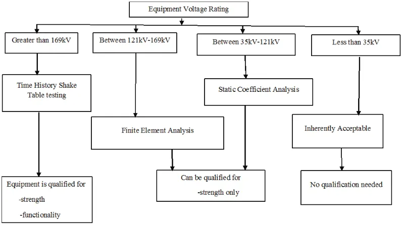
For the purpose of this study, the dynamic characteristics of an actual Gas Insulated substation (GIS) equipment has been studied. The current practice of the qualification of such a substation is based on the voltage rating of the equipment. Figure 1 shows the current approach as recommended by IEEE-693.
Figure 1. Recommended qualification process for GIS equipment as per IEEE-693 (2005)
IEEE-693 also recommends that in cases where the equipment is too large to fit on the shake table, a sub-assembly may be tested in accordance with IEEE-693 guidelines. However, such sub-sub-assembly tests do not account for interaction between multiple units as well as dynamic interaction between the equipment, associated cable conduits and the connected building support structures. This paper identifies the uncertainties associated with such qualification process and proposes a hybrid methodology for the qualification of substation equipment using finite element models that have been reconciled with shake table test results. The methodology makes an attempt to account for both strength and functionality requirement for the qualification. It has also been identified that the results from typical shake table test are not necessarily representative of true behaviour of an actually mounted unit.
PROPOSED APPROACH TO SEISMIC QUALIFICATION OF SUBSTATION EQUIPMENT
The guidelines of IEEE-693 recommends shake table tests for qualifying equipment with voltage rating greater than 169 kV. For equipment with lower voltage capacity, a finite element analysis is deemed fit for qualification. However, the functionality of an equipment is ensured if the entire system along with its associated instruments stay operational during and after the test. Therefore, in case of equipment that are qualified by analysis, the functionality of the instruments cannot be evaluated due to lack of any functionality criterion.
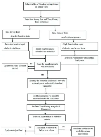
Figure 2. Proposed approach for equipment qualification.
As can be observed from the flowchart, a subassembly or the complete equipment is tested on a shake table for both sine sweep as well time histories, as recommended by IEEE-693. The results of the sine sweep tests can be used to identify the dynamic characteristics of the equipment. Accordingly, a finite element model can be created that reconciles with the shake table test results. The structural differences between the test equipment and that actually installed at the site can be identified and can be used to characterize the uncertainties associated with the testing and qualification of the equipment.
reconciled model can be considered to be qualified if the maximum acceleration responses from the finite element analyses are less than the test responses. A key aspect in the proposed approach is to identify the factors that introduce differences in the reconciliation between test and analysis results. These differences can be used to characterize the uncertainties in the model. These uncertainties make the dynamic behaviour of the system to be non-deterministic and subsequent probabilistic studies may be necessary to assess the seismic vulnerability of such systems.
The next section of this paper identifies such uncertainties in the system that can be used for an improved understanding of the behavior of such equipment.
UNCERTAINTIES ASSOCIATED WITH THE DYNAMIC CHARACTERISTICS OF THE EQUIPMENT
Uncertainty in Ground Motion
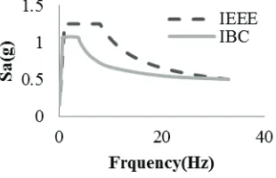
IEEE-693 specifies the response spectra for the qualification of the substation equipment. However, this specification is intended to be used in the qualification of equipment that is located at the ground level. Therefore, such spectra cannot be directly used for equipment that is mounted at an elevated building floor. The design of a multi-story building is guided by the appropriate building code (typically, the UBC or IBC). The earthquake input at the base of the building as recommended by such codes of practice are very different from that specified by IEEE-693. Figure 3 compares the response spectrum of IBC 2009 with the IEEE-693 (2005) spectrum (both scaled to have the same anchoring PGA of 0.5g).
Figure 3. Uncertainty in ground motion: Comparison of response spectra (IEEE-693 and IBC 2009).
Uncertainty due to limited availability of data
The reconciliation of the test and analysis results is obtained by a comparison of the transfer functions at various accelerometer locations as evaluated from sine sweep tests with inputs in the X and Y directions. The dynamic characteristics of the finite element model, namely, the modal frequencies, mode shapes and participation factors are used in a closed form formulation to obtain the transfer functions corresponding to the analysis results. Figure 4 compares the transfer functions for a particular accelerometer location of the equipment.
As can be observed from Figure 4, there is good reconciliation of the test and analysis results. Such reconciliation cannot be achieved by using inverse solution of the closed form equation for the transfer functions for the following reasons:
(b) The inverse solution requires information about all the modes which is impractical for real life multi degree of freedom systems.
Figure 4. Reconciliation of test and analysis results for X and Y directions.
For all practical purposes, data is available for the peak frequencies and for only the first few modes. Therefore, the available data may not be true representative of the complete dynamic behaviour of the system.
Uncertainty in the damping characteristics of system
The incomplete knowledge of damping characteristics of the system can also add to the uncertainty in the behaviour of the equipment. Figure 5 compares the effect of damping ratios on the peak response with the test response.
Figure 5. Uncertainty in response due to damping characteristics of the system.
As can be seen from the figure, with the increase in damping, the peak value of the transfer function approaches the test value. Hence, damping is a very important criterion to be considered for the reconciliation of test and finite element analysis results.
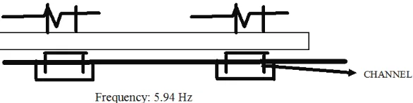
Uncertainty in the mounting condition
boundary condition, the mounting arrangement is pinned at two points, as shown in Figure 6(c). Therefore, the effect of mounting arrangement can have a pronounced effect on the dynamic characteristics of the equipment in its actual installed condition at the site.
Figure 6.Effect of boundary condition of mounting arrangement on the frequency of the equipment
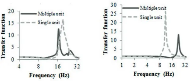
Interaction between multiple units of the equipment
Figure 7. Uncertainty in natural frequency due to interaction between multiple units of equipment.
Interaction between the building and the equipment
In most practical cases, the entire equipment is mounted inside a building. Therefore, the dynamic characteristics of the equipment will be affected by the interaction between the building and equipment. The mass of the equipment is usually about ten percent of the floor mass of the building. In order to understand the effect of interaction between the building and the system we can consider the building as the primary system and the equipment as the secondary system. If the equipment is rigid, similar to the conditions of the shake table test, there is no interaction between the building and the equipment. However, if the equipment has flexible mounting arrangement, as the actual in-situ conditions, then there can be significant mass interaction between the equipment and the building.
If the equipment is mounted on the floor slab in the building, the floor spectrum generated from a finite element analysis of the building can be used for understanding the dynamic characteristics of the equipment and qualify it for strength and functionality. The floor spectrum can be generated by analyzing the building and the equipment separately (uncoupled system) or by a single step analysis of the building and the equipment as together (coupled system). The uncoupled analysis does not consider mass interaction, whereas a couple analysis accounts for mass interaction between the primary and secondary system.
The following section shows a simple single degree of freedom (sdof) – single degree of freedom (sdof) primary-secondary system to illustrate the effect of mass interaction on the response spectra for a coupled analysis.
Coupled system: Effect of mass interaction
The equation of motion for a sdof primary – sdof secondary (2-dof coupled) system is:
where, mp is the mass of the primary system, ms is the mass of the secondary system, Cp and Cs are the
damping constants for the primary and secondary systems, Kpand Ksare the stiffness for the primary and
secondary systems, respectively.
is the input ground motion, up(t) and us(t) are the displacement responses for the primary and
secondary degrees-of-freedom respectively.
The first equation becomes:
where, r is the mass ratio.
The second equation can be written as:
On the other hand, if we do an uncoupled analysis, the equation of motion for the secondary system is:
where, is the total acceleration at the primary system degree of freedom.
A comparison between (4) and (5) shows that the response of the secondary system in the case of a coupled analysis is influenced by the behavior of the primary system and the interaction between the two cannot be captured by an uncoupled analysis in the complete sense as seen in (5).
Figure 8 shows the plots of floor spectra for a sdof-sdof primary-secondary system. In case of the uncoupled analysis, the floor time history generated from a finite element analysis of the primary system is used to generate the floor spectrum for the secondary system. The coupled analysis has been conducted for mass ratios of 0.1, 0.01 and 0.001 between the primary and the secondary system. The primary system is assumed to have a natural frequency of 4 Hz. As can be seen from the plots, the effect of mass interaction is quite significant for mass ratios of 0.1 and 0.01. It causes a reduction in the peak values for frequencies around 4 Hz. The two systems are said to be tuned when their fundamental frequencies are closer to each other. Therefore, the effect of mass interaction on the response is most prominent for tuned systems. However, as we decrease the mass ratio further to 0.001, effect of mass interaction is almost negligible and the response is similar to an uncoupled analysis.
0 5 10 15 20 25 30 35
1 10 100
S
a
(
g
)
Frequency (Hz)
Mass Ratio 0.001
Mass Ratio 0.01
Mass Ratio 0.1
Uncoupled Analysis
Figure 8. Uncertainty in the response spectra due to mass interaction between building and equipment.
CONCLUSION
Continued availability of offsite power can be a key factor in maintaining the safe operation and avoiding accidents in a commercial nuclear power plant. Since the substation supplying the power is usually located at a site away from the nuclear plant, the qualification of the equipment of the substation may often follow guidelines not set down directly by the nuclear regulatory agencies. Under such situations, the seismic vulnerability of such substation depends on the seismic response of its individual equipment as well as the effect of different uncertainties inherent in them. A methodology is proposed for qualification of electrical substation equipment for both strength and functionality assessment. In addition, reconciliation of experimental and analytical results is used to identify the uncertainty in various characteristics of such equipment.
The important factors that contribute to the uncertainty in the seismic behavior of equipment in an offsite electric substation are as follows:
! Uncertainty due to input ground motion
! Uncertainty in the frequency due to limited availability of data
! Significance of damping characteristics of the equipment
! Effect of mounting arrangement on the system response
! Interaction between multiple interconnected equipment in the substation
! Interaction between the building and the equipment
The present study attempts to illustrate the seismic behaviour of substation equipment by considering the effect of different in-situ conditions that are significant to characterize the uncertainty in the dynamic response of the system. It also emphasizes the incorporation of the effect of these uncertainties while qualifying the equipment at an actual site.
REFERENCES
Djordjevic,W., and O’Sullivan, J. J. (1990). ‘‘Guidelines for development of incabinet amplified response
spectra for electrical benchboards and panels,’’Rep. No. EPRI-NP-5223, Stevenson & Associates,
Djordjevic, W. (1992). ‘‘Amplified response spectra for devices in electrical cabinets,’’Proc., 4th Symp. on Current Issues Related to Nuclear Power Plant Structures, Equipment and Piping, Orlando, Fla. Eide, S. A., Gentillon, C. D., Wierman, T.E., Rasmuson, D. M. (2005). “Reevaluation of Station Blackout
Risk at Nuclear Power Plants (Analysis of Loss of Offsite Power Events: 1986-2004),” U.S.
Nuclear Regulatory Commission, NUREG/CR-6890.
Ersoy, Selahattin, and Saadeghvaziri, M. Ala. (2004). “Seismic Response of Transformer-Bushing
System,.” IEEE Transactions on Power Delivery, 19(1), 131-137.
IEEE 693, (2005). “IEEE recommended practice for seismic design of substations”. IBC (2009). “International Building Code.”
Katona, T., Kennerknecht, H., and Henkel F. O. (1995). ‘‘Earthquake design of swithgear cabinet of the
VVER-440/213 ar Pake,’’ Trans. 13th Int. Conf. on Structural Mechanics in Reactor Technology
(SMiRT-13), Porto Alegre, Brazil, 435–440.
Lee, B. J., and Abou-Jaoude, C. (1992). ‘‘Effect of base uplift on dynamic response of electrical and
mechanical equipment,’’ Seismic Engineering, PVP, ASME, 237(2), 145–150.
Llambias, J. M., Sevant, C. J., and Shepherd, D. J. (1989). ‘‘Nonlinear response of electrical cubicles for
fragility estimation,’’ Trans. 10th Int. Conf. on Structural Mechanics in Reactor Technology,
Anaheim, Calif., 893–897.
Paolacci, F., and Giannini, R. (2009). “Seismic reliability assessment of a high voltage disconnect switch
using an effective fragility analysis,”Journal of Earthquake Engineering, 13(2), 217-235.
Stafford, J. R. (1975). ‘‘Finite element predictions of the dynamic response of power plant control
cabinets,’’ Proc., 2nd ASCE Specialty Conf. on Structural Design of Nuclear Plant Facilities, New
York.
Whittaker, A. S., Fenves, G.L., and Gilani, A. S. J. (2007). “Seismic evaluation and analysis of