Transactions of the 17th International Conference on Structural Mechanics in Reactor Technology (SMiRT 17) Prague, Czech Republic, August 17 –22, 2003
Paper # J04-1
A Pinball Method by Direct Localization of the Impact Area
K.Petkevicius1)
,
R.Kulak2),
and A.Marchertas2)1) Kaunas University of Technology, Lithuania 2) Argonne National Laboratory, USA
ABSTRACT
A new impact/contact algorithm is described. It is based on the well known pinball algorithm presented in [1]. The new algorithm was implemented into the NEPTUNE code [2, 3]. To verify/validate the developed algorithm and procedures, several experiments that dealt with contact/impact were modeled and numerical simulations of the transient dynamics were performed. The first simulation was of a thin walled pipe impacting against a rigid steel plate and the second simulation was of a thin walled pipe impacting against a concrete slab [4]. In the third simulation, the transient dynamics of a clamped beam struck transversely by a mass was analyzed [5]. The results of the three analyses show good correlation with available experimental data.
KEY WORDS: impact, contact, shell, concrete, FEM, central difference, explicit time integration, splitting penalty method.
INTRODUCTION
The modeling of the mechanics of impact-contact of shell structures can be performed using the splitting pinball method [1]. In this method, a pinball is associated with each element and the radius of the pinball is always chosen so that it completely envelops each shell element. This initial pinball is called the parent pinball. Overlap of parent pinballs in the event of imminent contact only indicates the possibility of interpenetration. Whenever overlap of the parent pinballs is detected and penetration does not occur, another level of smaller pinballs is introduced. Eventually the diameters of the pinballs in the hierarchy are made equal to the thickness of the shell. In case of overlap or penetration detection at this level, then penalty forces are applied to these pinballs.
Because the pinball hierarchy method is not as fast as the original pinball algorithm, it was proposed to check the nodal position of one quadrilateral to that of the other quadrilateral element and avoid the splitting process, which starts from the parent pinball level. The proposed algorithm for direct localization and definition of the distance between the two quadrilateral elements was found to be effective. It demonstrated a remarkable decrease in computational time.
DIRECT LOCALISATION OF IMPACT AREA
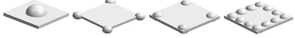
The direct localization of the impact area of two shells or plates can be performed at every step during explicit time integration. For this purpose, several pinballs are generated in the quadrilaterals of the projectile. A number of pinballs are required to obtain to the required precision. At the lowest level only one pinball would be required, which is located in the center of a quadrilateral finite element. If one pinball does not satisfy the precision requirements, then the number of pinballs can be increased as shown in the Fig. 1.
Fig. 1 Different splitting of projectile quadrilateral
− = + − + − − = + − + − − = + − + − z z z z z z z y y y y y y y x x x x x x x P Q D n P P v P P u P Q D n P P v P P u P Q D n P P v P P u 1 1 4 1 2 1 1 4 1 2 1 1 4 1 2 ) ( ) ( ) ( ) ( ) ( ) (
(1)
where D is the distance between the pinball center and the middle surface of the target element; u and v are local co-ordinates on the target element; nx, ny, nz are projections of the vector connecting the pinball center and target element;
P1x,P1y,P1z, …, P4x, P4y, P4z are nodal co-ordinates of the target element; Qx, Qy, Qz are co-ordinates of the center of the
pinball.
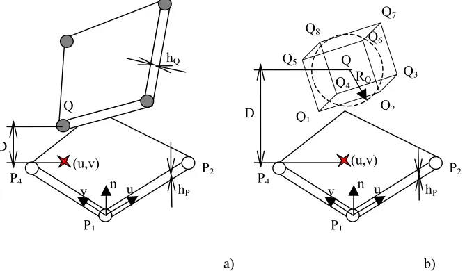
As shown in the Fig. 2a, the impact contact conditions for two quadrilaterals could be considered to occur when:
(
0 1)
(
0 12 ∩ ≤ ≤ ∩ ≤ ≤
+
<h h u v
D Q P
)
,
(2)where hQ and hP are the thicknesses of the projectile and the target shells. If the projectile is modeled using eight-node hexahedra, as shown in the Fig. 2b, then only one pinball is required within the hexahedra, thus:
(
0 1)
(
0 12 ∩ ≤ ≤ ∩ ≤ ≤
< +h u v
R
D P
Q
)
,
(3)where RQ is a pinball radius. This radius can be found assuming that the pinball volume is equal to the volume of the hexahedra. Q RQ Q8 Q7 Q6 Q5 Q4 Q3 Q2 Q1 P4 P1 n (u,v) D hP u v Q P4 P2 P1 n (u,v) D hP hQ u v P2
a) b)
Fig. 2 Localization of projectile pinballs to target shell
The calculation sequence for the direct localization algorithm is as follows: 1. Compute displaced nodal co-ordinates.
2. Loop over elements to find the global normal vectors.
3. Loop over all undamaged elements of the target to determine the penetrating pairs of elements: - Loop over all undamaged elements of projectile:
- Loop over all pinballs in the projectile elements to compute the distance and local co-ordinates of the projection point onto the target element:
- Compute the global co-ordinates of the pinball projection onto the target element plane and distance (1), - If the projectile pinball projects onto the target element and the distance is less than half of the sum of
the thicknesses of the projectile and target elements, then: - Compute the magnitudes of penetration and penetration ratio, - Compute the penalty forces,
- Add penalty forces to the nodes of the projectile and target.
The penalty forces, which are acting at the impact point, are directed along the line that connects the pinball center of the projectile and impact point of target. Distribution of penalty force to element nodes are performed using shape functions. When elements with single point integration are used, then equal distribution of the penalty force to all nodes of the quadrilateral can provide a stable load case and preclude hourglassing in the elements.
VERIFICATION PROBLEMS
Impact of a whipping pipe onto a rigid slab
An experiment of a whipping pipe impacting onto a rigid steel slab is reported in [4]. A finite element model of the pipe was developed and is shown in Fig. 3. The results of numerical analysis using node-to-surface contact finite elements were presented in [5]. In this study, the more general localized pinball algorithm was used. Figure 3 shows the dimensions (inches) of the cantilever supported pipe and the location of the rigid plate and the hydrodynamic force that occurs after a guillotine pipe break.
13500 lbf 144
R4.5
8 8
Fig. 3 Finite element model of whip pipe impact onto a steel plate
Because of symmetry, only one-half of the pipe and the rigid plate were modeled. The outside diameter of this pipe is 3.2 inches and the wall thickness is 0.3 inches. The material properties of the steel pipe are presented in Table 1. The elastoplastic behavior of the pipe was described using a bilinear stress-strain curve. The steel contact plate was treated as an elastic material. The mass of the water-steam mixture inside the pipe was added to the steel density.
Table 1. Material properties of the steel pipe and plate
Material ρ [ kg/m3] E [Pa] σ
y [Pa] Et [Pa] σy1 [Pa] ν Damping
Pipe with water 10630 2.00·1011 2.20·108 5.86·108 4.00·108 0.3 0.02
Plate 7800 2.00·1011 0.00e+0 5.86·108 4.00·108 0.3 0.02
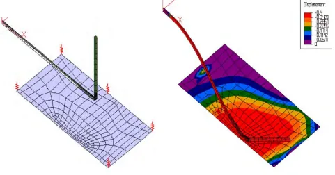
The comparison of experimental and finite element results is presented in Table 2. Local and global pipe deformations are shown in Fig. 4. Figure 4b also compares the global pipe deformations with the pipe model used in [5]; that model used two-node pipe elements and node-to-surface contact elements [3] and also showed good agreement. The differences between the finite element and experimental results do not exceed 7-11%.
Table 2. Comparison of finite element and experimental results of pipe impact onto a rigid plate
Parameter Direct localization algorithm Experiment
1. Time to impact [ms] 9.25 10.0
2. Impact duration [ms] 1.5 1.3
3. Time to obtain maximum impact force [ms] 0.75 0.8
4. Maximum impact force [N] 4.27·105 3.85·105
a) b)
Fig. 4 Local (a) and global (b) deformations of the pipe
Impact of a whipping pipe onto a deformable concrete slab
The results of pipe impact onto a concrete slab were also presented in [4]. The FE model developed to simulate this experiment is shown in Fig. 5.
Fig. 5 A FE model of whip pipe impact onto concrete slab
The pipe is modeled, as in the previous simulation, with quadrilateral plate elements. The dimensions of the concrete slab are 3.048 m x 3.048 m x 152.4mm. The initial gap between the pipe and the slab is 1.024 m. The concrete slab is modeled with reinforced concrete quadrilateral plate elements from the NEPTUNE element library [2]. The compressive strength of the concrete was reported to be 60.5 MPa and the percent reinforcement was 150 kg/m3. The
steel rebars are located in four symmetrical layers. The slab is supported on eight load cells, which were modeled with elastic bar elements.
The load is applied as an internal pressure of 16.55 MPa on the elbow region, which results from the hydrodynamic forces occurring after the pipe break. Also gravitational forces of pipe including water weight were taken into account. Because of the high kinetic energy of the water-steam mixture inside the pipe, a momentum flux arises that resists pipe bending. To model this hydrodynamic reaction, additional weightless, hydrodynamic pipe-elements were included and loaded by the internal hydrodynamic flow.
Table 3. Comparison of finite element and experimental results of a pipe impacting against a concrete slab
Parameter Direct localization algorithm Experiment
1. Time to impact [ms] 69 69
2. Time to obtain maximum impact force [ms] 2.4 2.5
3. Maximum impact force [N] 8.23·105 8.49·105
4. Maximum total reactions [N] 6.45·105 4.98·105
5. Residual deflections of concrete slab [mm] 9.91 7.01
The z-displacement of concrete slab is presented in the Fig. 5. It is seen that the maximum displacement of the concrete is about 3.5 inches. The concrete in many elements reaches complete softening. The reinforcement bars, however, have not failed and still provide structural support. Figure 6 shows the evolution of the total reaction force for the half-model.
-100000 -50000 0 50000 100000 150000
0.00E+00 2.00E-02 4.00E-02 6.00E-02 8.00E-02 1.00E-01 1.20E-01 1.40E-01 1.60E-01
time,s Total
Fig. 6 Temporal evolution of the total reactions for the half-model
A clamped beam struck transversely by a mass
The final verification/validation study was a comparison of simulation results with experimental results from a series of experiments reported in [6] in which a clamped beam was struck transversely by a mass. The experiments were performed on aluminum clamped beams of various dimensions as shown in Table 4. The material properties are given in Table 4 and the materials Cauchy stress-strain diagram is given in Table 5.
Table 4. Geometric data and material properties of clamped beams
Length [mm] Height [mm] Width [mm] modulus [Pa] Young’s Poisson ratio Density [kg/m3]
108 3.81; 5.08; 6.35 10.8 7.00E+10 0.3 2700
Table 5. Cauchy stress strain diagram for aluminum specimens
Point 1 2 3 4 5
ε 5.93E-03 1.42E-02 4.74E-02 1.35E-01 2.09E-01
Fig. 7 FE model of a beam struck transversely by a mass
Table 5. Comparison of experimental and NEPTUNE FEA results of beams struck transversely by a mass
Residual maximum displacement/thickness
Specimen Thickness [mm] Mass velocity [m/s]
Experimental NEPTUNE
Diff.%
ALI4 ALIII1 ALIII2 ALIII4 ALIII5
3.81 6.35 6.35 6.35 6.35
4.44 5.34 6.29 1.78 3.81
3.11 1.70 2.03 0.37 1.20
3.22 1.67 2.03 0.41 1.17
-3.5
0.0 -10.8
2.5 1.8
Quadrilateral plate elements were used to model one-half of the clamped beam. The striking mass was modeled using one quadrilateral plate element. The model discretization is shown in Fig. 5.
A comparison of experimental and analytical results is presented in the Table 5. There seems to be good agreement between experimental and finite element results for the residual deflections.
SUMMARY
The direct localization of the impact area algorithm originated during the development of a surface detection procedure for a finite element penetration algorithm. It was implemented and used with the contact-impact procedure known as the pinball method. In this explicit method, the contact surface is defined by the overlap of the contacting bodies when integrated without interaction. A penalty method is used with the pinball algorithm. In many problems of importance in engineering, impact and contact can develop between different shells. The direct localization of contact area between two quadrilateral elements reduces computational time.
The development of a suite of algorithms for complex nonlinear transient analysis of contact, impact and penetration of nuclear power plant reinforced concrete structures was completed. Detail verification/validation studies were performed on the following contact-impact problems:
- a whipping pipe impacting onto a rigid plate; - a whipping pipe impacting on a concrete slab; - clamped beams struck transversally by a mass.
The results of the current investigation show that the proposed algorithm of direct localization of impact area could be used to efficiently simulate the complex mechanics that occurs in impact-contact problems when using explicit time integration.
ACKNOWLEDGEMENT
NOMENCLATURE
D - distance between pinball center and middle surface of target element;
u,v - local co-ordinates on target element;
nx, ny, nz - projections of vector connecting of pinball center and target element;
P1x,P1y,P1z, …,
P4x, P4y, P4z - nodal co-ordinates of target element;
Qx, Qy, Qz - pinball co-ordinates.
REFERENCES
1. Belytschko, T. and Yeh, I.S., “The splitting pinball method for contact-impact problems”, Meth. in Appl. Mech. and Engr., Vol. 105, 1993, pp. pp.375-393.
2. Kulak, R. F., and Fiala, C., “NEPTUNE: A system of finite element programs for three-dimensional nonlinear analysis”, Nuclear Engineering and Design, Vol, 106, 1988, pp. 47-68.
3. Kulak, R. F., “Adaptive contact elements for three-dimensional explicit transient analysis”, Comp. Meth. In Appl. Mech. and Eng., Vol. 72, 1989, pp. 125-151.
4. Garcia, J.L., Chouard, Ph. and Sermet, E., “Experimental studies of pipe impact on rigid restrains and concrete slabs”, Nuclear Engineering and Design, Vol. 77, 1984, pp. 357-368.
5. Kulak, R. F. and Narvydas, E., “Validation of the NEPTUNE computer code for pipe whip analysis”, Transactions
of Structural Mechanics in Reactor Technology, SMiRT 16, Paper # 1124, 2001.