Enterprise Communications Server
Release 6
CallVisor
®
PC ASAI
Notice
While reasonable efforts were made to ensure that the information in this document was complete and accurate at the time of printing, Lucent Technologies can assume no responsibility for any errors. Changes and corrections to the information contained in this document may be incorporated into future reissues.
Your Responsibility for Your System’s Security
You are responsible for the security of your system. Lucent Technologies does not warrant that this product is immune from or will prevent unauthorized use of common-carrier telecommunication services or facilities accessed through or connected to it. Lucent Technologies will not be responsible for any charges that result from such unauthorized use. Product administration to prevent
unauthorized use is your responsibility and your system
administrator should read all documents provided with this product to fully understand the features available that may reduce your risk of incurring charges.
Federal Communications Commission Statements Part 15: Class A Statement. This equipment has been tested and found to comply with the limits for a Class A digital device, pursuant to Part 15 of the FCC Rules. These limits are designed to provide reasonable protection against harmful interference when the equipment is operated in a commercial environment. This
equipment generates, uses, and can radiate radio-frequency energy and, if not installed and used in accordance with the instruction manual, may cause harmful interference to radio communications. Operation of this equipment in a residential area is likely to cause harmful interference, in which case the user will be required to correct the interference at his or her own expense.
Part 68: Network Registration Number. This equipment is registered with the FCC in accordance with Part 68 of the FCC Rules. It is identified by FCC registration number
AS593M-13283-MF-E.
Part 68: Answer-Supervision Signaling. Allowing this equipment to be operated in a manner that does not provide proper answer-supervision signaling is in violation of Part 68 rules. This equipment returns answer-supervision signals to the
public-switched network when: ■ Answered by the called station ■ Answered by the attendant
■ Routed to a recorded announcement that can be administered by the CPE user
This equipment returns answer-supervision signals on all DID calls forwarded back to the public-switched telephone network. Permissible exceptions are:
■ A call is unanswered ■ A busy tone is received ■ A reorder tone is received
Trademarks
CallVisor is a registered trademark of Lucent Technologies. DEFINITY is a registered trademark of Lucent Technologies in the USA and throughout the world.
CentreVu Computer-Telephony is a registered trademark of Lucent Technologies.
SPARC Solaris is a trademark of Sun Microsystems, Inc. in the USA and other countries.
Solaris is a trademark of Sun Microsystems, Inc. in the USA and other countries.
UNIX is a registered trademark in the USA and other countries, licensed exclusively through X/Open Company Limited.
UnixWare is a registered trademark of the Santa Cruz Operation, Inc. in the USA and other countries.
Windows is a registered trademark of Microsoft Corporation. Windows NT is a trademark of Microsoft Corporation.
Ordering Information
The ordering number for this document is 555-230-227. To order this document, call the BCS Publications Center at 1 800 457-1235 (international callers use 1 317 322-6791). For more information about Lucent Technologies documents, refer to Business Communications Systems Publications Catalog, 555-000-010. You can be placed on a Standing Order list for this and other BCS documents you may need. Standing Order will enable you to automatically receive updated versions of individual documents or document sets, billed to account information that you provide. For more information on Standing Orders, or to be put on a list to receive future issues of this document, please contact the Lucent Technologies BCS Center.
To learn more about Lucent Technologies products and to order products, contact Lucent Direct, the direct-market organization of Lucent Technologies Business Communications Systems. Access their web site at www.lucentdirect.com, or call 1 800 451-2100. The International fax number is 1 317 322-6699.
Lucent Technologies Fraud Intervention
If you suspect you are being victimized by toll fraud and you need technical support or assistance, call the BCS Technical Service Center Toll Fraud Intervention Hotline at 1 800 643-2353.
Comments
To comment on this document, return the comment card at the end of the document.
Acknowledgment
This document was prepared by the Product Documentation Development, Lucent Technologies
Middletown, NJ 07748-9972
Copyright © 1998 Lucent Technologies All Rights Reserved
About This Document
xxi■ Reason for Reissue xxi
■ New features xxii
Single-Step Conference xxii
Universal Call ID xxii
Release 5 Major Enhancements xxii
■ Intended Audience xxiv
■ Organization of This Document xxv
■ Related Documents xxvi
■ Technical Service Center xxvi
1
Installation
1-1■ Platform Consideration 1-1
Hardware Platforms 1-1
■ CV/LAN Product Description 1-11
System Configuration 1-14 Software Configuration 1-14 System Operation and Limits 1-14 Server Installation on UNIX 1-15 Client Installation on UNIX 1-15 Client Installation on Windows NT 1-15 Running the Sample Application 1-16
■ DEFINITY ECS Administration 1-17
■ Configuration 1-18
Upgrading Software 1-18
Removing Software 1-18
Contents
2
OA&M
2-1■ The ASAI Log File 2-2
■ OA&M Manual Pages 2-3
■ admin(7) 2-4
■ asai(4) 2-5
■ asai(7) 2-6
■ asai.Date(4) 2-7
■ asai.Name(4) 2-8
■ asai_admin(1) 2-9
■ asai_cause(1) 2-11
■ asai_hb(1) 2-14
■ asai_log(4) 2-16
■ asai_test(1) 2-17
■ asai_trace(1) 2-18
■ asai_ver(1) 2-21
■ boot.bin(4) 2-22
■ cmd(7) 2-23
■ command(7) 2-24
■ esai_alarm(1) 2-25
■ esai_trace(1) 2-27
■ ipci(4) 2-29
■ ipci_admin(1) 2-30
■ ipci_off(1) 2-33
■ ipci_on(1) 2-34
■ ipci_stat(1) 2-36
■ ipci_test(1) 2-37
■ ipci_ver(1) 2-38
■ isdn_alarm(1) 2-39
■ isdn.Date(4) 2-41
■ isdn_11_r(1) 2-42
■ isdn_12_r(1) 2-43
■ isdn.Name(4) 2-44
■ isdn_trace(1) 2-45
■ link_alarm(1) 2-50
■ link_change(1) 2-51
■ link_offline(1) 2-52
■ link_restart(1) 2-53
■ link_status(1) 2-54
■ log_msgs(4) 2-55
■ pcisdn.bin(4) 2-56
■ signal(7) 2-57
■ CV/LAN Administration 2-58
OA&M changes for client and server 2-58
3
Introduction to ASAI
3-1■ Terms and Concepts 3-3
■ Important Note about Heartbeat 3-4 ■ The ASAI Library Functions 3-5 ■ Application Service Elements 3-8
■ ASAI Capabilities 3-11
4
ASAI Library Functions
4-1■ asai_open( ) 4-3
■ asai_errval ( ) 4-4
■ asai_set_env( ) 4-6
■ asai_get_env( ) 4-9
■ asai_send( ) 4-10
■ asai_rcv( ) 4-12
■ asai_close( ) 4-13
Contents
5
ASAI Capabilities
5-1■ Event Notification 5-2
■ Event Notification Request 5-3
Description 5-3
Request/Indication Parameters 5-3
Notes 5-3
■ Event Notification End 5-4
Description 5-4
Notes 5-4
■ Event Notification Cancel 5-5
Description 5-5
Notes 5-5
■ Event Notification Stop Call Notification 5-6
Description 5-6
Request/Indication Parameter 5-6
Notes 5-6
■ Event Report 5-7
Description 5-7
■ Third Party Call Control Capabilities 5-11 ■ Third Party Answer Call 5-13
Description 5-13
Request/Confirmation Parameters 5-13
Notes 5-13
Interactions with Event Reports 5-13
■ Third Party Auto Dial 5-14
Description 5-14
Request/Confirmation Parameters 5-14
Notes 5-15
Related Event Reports 5-15
■ Third Party Call Ended 5-16
Description 5-16
Request/Confirmation Parameters 5-16
Notes 5-16
■ Third Party Clear Call 5-17
Description 5-17
Notes 5-17
Interactions with Event Reports 5-17
■ Third Party Domain Control 5-18
Description 5-18
Request/Confirmation Parameter 5-18
Notes 5-18
Interactions with Event Reports 5-18
■ Third Party Domain Control End 5-19
Description 5-19
Notes 5-19
Interactions with Event Reports 5-19
■ Third Party Listen-Disconnect 5-20
Description 5-20
Request/Confirmation Parameters 5-20
Notes 5-20
Interactions with Event Reports 5-20
■ Third Party Listen-Reconnect 5-21
Description 5-21
Request/Confirmation Parameters 5-21
Notes 5-21
Interactions with Event Reports 5-21
■ Third Party Make Call 5-22
Description 5-22
Request/Confirmation Parameters 5-22
Notes 5-23
Interactions with Event Reports 5-24
■ Third Party Merge 5-25
Description 5-25
Contents
Request/Confirmation Parameters 5-27
Notes 5-27
Interactions with Event Reports 5-27
■ Third Party Redirect Call 5-28
Description 5-28
Request/Confirmation Parameters 5-28
Notes 5-28
Interactions with Event Reports 5-28
■ Third Party Relinquish Control 5-29
Description 5-29
Notes 5-29
Interactions with Event Reports 5-29
■ Third Party Selective Drop 5-30
Description 5-30
Request/Confirmation Parameters 5-30
Notes 5-30
Interactions with Event Reports 5-31
■ Third Party Selective Hold 5-32
Description 5-32
Request/Confirmation Parameters 5-32
Notes 5-32
Interactions with Event Reports 5-32
■ Third Party Send DTMF Signals 5-33
Description 5-33
Request/Confirmation Parameters 5-33
■ Third Party Single-Step Conference 5-34
Description 5-34
Request/Confirmation Parameters 5-34
Notes 5-34
■ Third Party Take Control 5-35
Description 5-35
Request/Confirmation Parameters 5-35
Notes 5-35
Interactions with Event Reports 5-35
■ Set Value Capabilities 5-36
Description 5-36
Request/Indication Parameters 5-36
■ Value Query Capabilities 5-37
■ Value Query 5-38
Description 5-38
Request Parameters 5-38
Notes 5-39
■ Value Query Response 5-40
Description 5-40
Request Parameter 5-40
Notes 5-40
■ Request Feature Capabilities 5-41
Description 5-41
Request/Indication Parameters 5-41
Notes 5-42
■ Adjunct Routing Capabilities 5-43
■ Routing 5-44
Description 5-44
Request/Indication Parameters 5-45
Notes 5-45
■ Route Select 5-46
Description 5-46
Request/Indication Parameters 5-46
Notes 5-47
■ Route End 5-48
Description 5-48
Notes 5-48
■ Maintenance Capabilities 5-49
■ Heartbeat 5-50
Contents
Request/Indication Parameters 5-51
Notes 5-51
6
CV/LAN Programming
6-1■ Introduction to CV/LAN 6-1 ■ Applications Development Environment 6-1
UNIX Platforms 6-1
Windows NT Platform 6-2
Future Upgrade Considerations 6-3
Client API 6-3
■ asai_open 6-5
Description 6-5
■ asai_errval 6-6
■ asai_set_env() 6-6
■ asai_get_env() 6-7
Description 6-7
■ asai_send() 6-8
Description 6-8
■ asai_rcv() 6-9
Description 6-9
■ asai_close() 6-10
Description 6-10
7
Error Messages
7-1■ Library Error Messages 7-1
8
ASAI Capability Primitives
8-1■ asai_common 8-3
call_id 8-5
party_id 8-6
old_party_id 8-6
trunk_id 8-7
plan_type 8-7
number_id 8-7
party_ext 8-8
stn_info 8-8
merge_ext 8-8
user_user 8-9
user_data 8-9
oli 8-10
ucid 8-10
■ cause_value 8-12
■ Pool 8-15
9
Programming Manual Pages
9-1■ ASAI Library Manual Pages 9-1 ■ Applications Development Environment for CV/LAN 9-2
UNIX Platforms 9-2
Windows NT Platform 9-2
■ ASAI Library Functions 9-3
■ asai_close (3ASAI) 9-5
■ asai_errval (3ASAI) 9-6
■ asai_get_env (3ASAI) 9-7
■ asai_open (3ASAI) 9-10
■ asai_rcv (3ASAI) 9-12
■ asai_send (3ASAI) 9-15
Contents
■ C_3PANS_CONF (3ASAI) 9-30
■ C_3PCC (3ASAI) 9-32
■ C_3PCC_CONF (3ASAI) 9-34
■ C_3PCE (3ASAI) 9-36
■ C_3PDC_CONF (3ASAI) 9-38
■ C_3PDC_REQ (3ASAI) 9-40
■ C_3PDCE (3ASAI) 9-42
■ C_3PM (3ASAI) 9-44
■ C_3PM_CONF (3ASAI) 9-46
■ C_3PMC_CONF (3ASAI) 9-49
■ C_3PMC_REQ (3ASAI) 9-52
■ C_3PR (3ASAI) 9-56
■ C_3PR_CONF (3ASAI) 9-58
■ C_3PRC (3ASAI) 9-60
■ C_3PRC_CONF (3ASAI) 9-62
■ C_3PREDIR (3ASAI) 9-64
■ C_3PREDIR_ACK (3ASAI) 9-66
■ C_3PSD (3ASAI) 9-68
■ C_3PSD_CONF (3ASAI) 9-71
■ C_3PSDS (3ASAI) 9-73
■ C_3PSDS_CONF (3ASAI) 9-76
■ C_3PSH (3ASAI) 9-78
■ C_3PSH_CONF (3ASAI) 9-80
■ C_3PSL_DISC (3ASAI) 9-82
■ C_3PSL_DISC_ACK (3ASAI) 9-84 ■ C_3PSL_RECONN (3ASAI) 9-86 ■ C_3PSL_RECONN_ACK (3ASAI) 9-88
■ C_3PSSC_REQ (3ASAI) 9-90
■ C_3PSSC_CONF (3ASAI) 9-92
■ C_3PTC_CONF (3ASAI) 9-95
■ C_3PTC_REQ (3ASAI) 9-97
■ C_ABORT (3ASAI) 9-99
■ C_EN_CAN (3ASAI) 9-101
■ C_EN_CAN_CONF (3ASAI) 9-102
■ C_EN_END (3ASAI) 9-106
■ C_EN_REP (3ASAI) 9-108
■ C_EN_REQ (3ASAI) 9-130
■ C_EN_SCN (3ASAI) 9-133
■ C_EN_SCN_CONF (3ASAI) 9-135
■ C_HB_CONF (3ASAI) 9-137
■ C_HB_REQ (3ASAI) 9-139
■ C_RF_CONF (3ASAI) 9-140
■ C_RF_REQ (3ASAI) 9-142
■ C_RT_END (3ASAI) 9-146
■ C_RT_REQ (3ASAI) 9-148
■ C_RT_SEL (3ASAI) 9-152
■ C_SV_CONF (3ASAI) 9-156
■ C_SV_REQ (3ASAI) 9-158
■ C_VQ_CONF (3ASAI) 9-161
■ C_VQ_REQ (3ASAI) 9-170
■ C_VQ_RESP (3ASAI) 9-175
10
Testing
10-1■ Integration Test Tool 10-1
Terminology 10-2
■ Executing the ITT Program 10-3
■ Scripts 10-4
stall 10-5
asai_open 10-6
asai_close 10-8
asai_send 10-9
Contents
Event Report — C_EN_REP 10-15
■ Manual Pages 10-18
■ close_dialog_out(3) 10-18
■ get_long(3) 10-19
■ get_string(3) 10-20
■ open_dialog_out(3) 10-21
■ parse(3) 10-22
■ print_common(3) 10-24
■ t_input(3) 10-25
■ t_output(3) 10-26
■ CV/LAN Testing 10-27
Overview 10-27
Scripts 10-27
11
Troubleshooting
11-1■ ECS Administration 11-2
■ Message Trace Capability 11-2
■ IPCI_ON 11-2
■ Application Programming 11-3
■ Cause Values 11-3
■ Nonblocking I/O 11-3
■ Integration Test Tool 11-3 ■ Responding to Heartbeat 11-3
■ Link Startup Failure 11-4
■ Detecting Failed ASAI Links 11-4
■ Version Selection 11-5
■ Inoperable System Errors 11-6 ■ CV/LAN Troubleshooting 11-7 ■ Client Side OA&M Utilities 11-7
asai_test 11-7
asai_ver 11-7
CVLN_ITT - ECS Connection Failure 11-7
A
Special Characters
A-1GL
Glossary
GL-11
Installation
1-1. CallVisor PC Adjunct-Server Configuration 1-11 1-2. CallVisor PC as a CV/LAN server 1-12
1-3. CallVisor PC Configuration — CV/LAN to MAPD 1-13
2
OA&M
2-1. An ASAI Log File 2-2
4
ASAI Library Functions
4-1. Opening a Communication Path 4-3
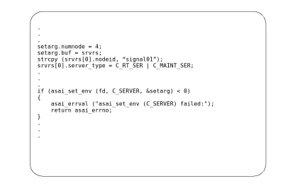
4-2. Using asai_errval (), Example 1 4-4 4-3. Using asai_errval (), Example 2 4-5 4-4. Setting the Library Environment: Node ID 4-6
4-5. Setting the Environment: Establishing a Server 4-7 4-6. asai_send () Function 4-11 4-7. asai_rcv () Function 4-12
4-8. Closing the Communication Path 4-13 4-9. Sample Code — Testing the Event
Notification Capabilities 4-15
5
ASAI Capabilities
5-1. Routing an Incoming Call 5-44
10
Testing
10-1. Integration Test Tool — Overview 10-1 10-2. Execution of the ASAI integration test tool 10-3
Figures
10-10. Call Alerting 10-16
10-11. Connected Report 10-16
10-12. Drop Report 10-16
1
Installation
1-1. Field Name and Requirements 1-17 1-2. Default IPCI Configuration Values 1-19
2
OA&M
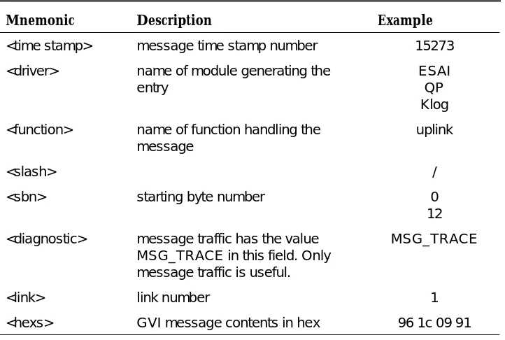
2-1. Format of esai_trace-Generated ESAI
Device Driver Messages 2-27
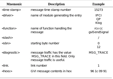
2-2. Format of isdn_trace-Generated IPCI
Device Driver Messages 2-45 2-3. Long Form Status Values 2-48 2-4. Common Status Values 2-49
3
Introduction to ASAI
3-1. ASAI Library Functions for Managing the
Communication Path 3-6
3-2. ASAI Library Functions for
Exchanging Information 3-7
3-3. ASAI Library Function for Handling Errors 3-7 3-4. ASAI Capabilities by Capability Group (ASE) 3-8 3-5. ASAI Abort Capabilities 3-10
3-6. Classification of ASAI Capabilities 3-11
4
ASAI Library Functions
4-1. ASAI Library Functions: A Typical Application 4-2
5
ASAI Capabilities
5-1. Valid Event Item Combinations 5-8
Tables
8
ASAI Capability Primitives
8-1. ASAI Library and the DEFINITY ECS
Cause Values 8-12
9
Programming Manual Pages
9-1. Redirection Reason Codes 9-115 9-2. Event-Name Members and Descriptions 9-116
9-3. Domain Value Parameters and Description 9-131 9-4. Associated Items and Descriptions for
C_VQ_CONF 9-165
9-5. Associated Items and Descriptions for
C_VQ_REQ 9-173
9-6. Associated Items and Descriptions for
C_VQ_RESP 9-176
10
Testing
10-1. Argument Types and Descriptions 10-22
This reference guide is for Lucent Technologies’ DEFINITY® Enterprise Communications Server (ECS) CallVisor® PC Adjunct-Switch Application Interface (ASAI) platform for UNIX® and Windows® NT™.
NOTE:
This documentcan be used with the earlier versions of DEFINITY Communications System products.
The information in this document relates to a specific implementation of an API for the ASAI protocol between an adjunct and the DEFINITY ECS. Emphasis is on the API rather than on the protocol, adjunct, or the DEFINITY ECS. Specific information concerning these other products is readily available in other
documents. See the section ‘‘Related Documents’’ at the end of this preface, or the documentation provided with your operating system, or computer.
The DEFINITY ECS utilizes the following products made by other software vendors:
■ Solaris™ of Sun Microsystems, Inc.
■ UNIX is licensed exclusively through X/Open Company Limited
■ UnixWare® of the Santa Cruz Operation, Inc. ■ Windows® of Microsoft Corporation
About This Document
New features
This section summarizes the new features up to Release 6.3.
Single-Step Conference
The Single-Step Conference allows applications to add a device into an existing call for the purpose of playing announcements or facilitating application-initiated transfers and conferences. This is accomplished with a single ASAI request, without the need for placing anyone on hold or initiating a new call.
Universal Call ID
Universal Call ID (UCID) is a unique tag assigned to each DEFINITY call. It is used by an application to track a call for its life, from origination to disconnect, regardless of where the call may end up and how it gets there (transfer, conference, routing, through a variety of network and the DEFINITY Enterprise Communications Servers, and voice responses, etc.).
The UCID is reported to all ASAI links on the DEFINITY ECS, if so administered. The event reports that contain the UCID are: Call Initiated, Call Offered, Alerting, Connected, Call Transferred, and Call Conferenced. Acknowledgments to Third Party Make Call, Third Party Auto-dial, Third Party Merge, and Third Party Take Control also contain UCID. The UCID is also passed in a Route Request Capability and UCID Query is also available in this release.
Release 5 Major Enhancements
■ Advice of Charge
This feature provides an ASAI application with the capability to receive information regarding the cost of an active outgoing call. It applies only in those countries where the network is able to send the cost of the current call to the DEFINITY ECS using the ISDN Advice of Charge feature.
■ Reason Codes
ASAI will allow adjuncts to enter a reason code when an agent’s work mode changes to AUX work or when an agent logs out. In addition, the adjunct can also query for an agent’s reason code status. This feature must be optioned and it is mandatory that the AUX Work Reason Codes and the Agent Logout Reason Codes be set to “forced” or “requested.”
■ ASAI Selective Listening
■ II-Digits
II-Digits provide information about the originating line. For example, these digits will indicate if the call is originating from a prison, a cellular system, a coin machine, or special operator, etc. II-Digits are passed to the
DEFINITY ECS by the network on Integrated System Digital Network Primary Rate Interface (ISDN-PRI) trunks and are then passed to the adjunct over an ASAI link. An ASAI application can use the information provided by II-Digits to properly route or provide special treatment for the incoming call. This feature can also be used to prevent fraud.
II-Digits will be populated in the Call Offered, Alerting, Connected Event Reports and in Route Request.
■ 27-Character Display
The ASAI-Accessed Integrated Directory query has been modified to return up to 27 characters for names when extensions are retrieved from the Integrated Directory of ECS. Link version 3 (G3V5), must be negotiated between the ECS and the adjunct for this enhancement to work (otherwise, only 15 characters will be passed). International Standards Organization (ISO) certified optrex characters are also included in the ASAI-Accessed Integrated Directory.
■ OPTREX Characters
Some newer phones support escape sequences to display certain
About This Document
Intended Audience
This document is intended for system administrators, programmers and testers. It provides step-by-step procedures for installation and administration of CallVisor PC. This document also describes the interaction between the UNIX ASAI adjunct and the DEFINITY ECS. It is intended to assist applications programmers in developing applications for the adjunct. It includes complete information on all the ASAI library functions, capabilities and capability primitives. Integration Test Tool (ITT) is designed to help in testing the library functions. A number of issues and problems that may be encountered during various phases, from installation to regular administration, are also addressed.
Organization of This Document
This document is organized as follows:
Chapter 1 provides detailed installation steps.
Chapter 2 provides the manual pages for commands, daemons, and files used in
administration.
Chapter 3 is an overview of the Adjunct-Switch Application Interface. It presents
the terms and concepts specific to ASAI and includes an overview of the ASAI library: the functions, the application service elements (ASEs) and the capability primitives.
Chapter 4 describes the ASAI library functions and their use and contains a
number of coding examples.
Chapter 5 has all the ASAI application service elements, providing details about
the capabilities that comprise each ASE.
■ Event Notification and Event Reports
■ Third Party Call Control Capabilities
■ Set Value
■ Value Query
■ Request Feature
■ Adjunct Routing
■ Maintenance
■ Abort Capabilities
Chapter 6 introduces a new feature — CV/LAN.
Chapter 7 has a detailed list of error returns from the library functions
Chapter 8 is an introduction to ASAI capability primitives.
Chapter 9 contains manual pages for ASAI library functions, ASAI capabilities
and primitive types in detail.
Chapter 10 is an overview of Integration Test Tool (ITT) and its functions.
About This Document
A Glossary and Index are also provided for easy access to terms and definitions.
Related Documents
For specific information concerning the DEFINITY ECS Release 6 ASAI, the following documents are available from Lucent Technologies Publications Center (1 800 457-1235) :
■ DEFINITY Enterprise Communications Server Release 6 CallVisor ASAI
Technical Reference, 555 230-220
■ DEFINITY Enterprise Communications Server Release 6 CallVisorASAI
Protocol Reference, 555 230-221
■ DEFINITY Enterprise Communications Server Release 6 Administration
and Feature Description, 555-230-522
■ DEFINITY Enterprise Communications Server Release 6 System
Description Pocket Reference, 555-230-211
■ DEFINITY ECS CallVisor ASAI DEFINITY LAN Gateway over MAPD
Installation, Administration, and Maintenance, 555-230-114
■ DEFINITY ECS CallVisor ASAI PC LAN over MAPD
Installation, Administration, and Maintenance, 555-230-113
■ CallVisor ASAI CD Document Set, 585-246-801
This CD ROM contains six CallVisor ASAI release 6 documents. It includes
CallVisor ASAI Technical reference, CallVisor ASAI Protocol Reference, CallVisor ASAI Overview, CallVisor ASAI PC, CallVisor ASAI DEFINITY LAN Gateway over MAPD Installation, Administration, and Maintenance, and CallVisor ASAI PC LAN over MAPD Installation, Administration, and Maintenance
Technical Service Center
The CallVisor PC helpline supports CallVisor PC customers who need technical assistance. Technical support is provided for installation, administration and functionality failures (“bugs”). The number of hours of technical support varies with the type of license purchased. The CallVisor PC helpline number is 1 732 957-5725.
1
This chapter provides all the information on the DEFINITY ECS administration, system configuration, operation, and limits which is required to install CallVisor PC. This chapter also covers the procedure to install CV/LAN on Windows NT and UNIX, and run the sample application.
Platform Consideration
ASAI supports the following operating system platforms (CallVisor PC server) :
1. SCO UnixWare 2.1.2 (including ptf32801)
2. Solaris 2.4 x86
3. Solaris 2.5 x86
Hardware Platforms
As a general guideline, if one of the above listed operating systems will run on the hardware platform, CallVisor PC will also run. You should first choose a software platform, (UnixWare or Solaris x86), and work from the Hardware Certification list provided with the operating system. If planning a CallVisor PC ISDN-BRI
installation, choose a PC model from the list with a clock speed below 90 MHz. A multi-CPU PC is not supported for either a PC-ISDN or LAN Gateway
Installation
There are two distinct types of ISDN board failures:
1. Inability to download the ISDN board firmware (failure to “pump”). This is discovered at installation time and can be diagnosed by checking the
/usr/adm/isdn/isdn_log file for errors during the pumping phase.
2. This is link traffic related. At link message rates, approximately 1/3 to 1/2 the bandwidth of the ISDN link (link bandwidth is 30 messages per second), the ISDN board will experience a hardware timeout, and the link will drop. The only recovery is to re-pump the board (ipci_OFF followed by ipci_ON). Again, the hardware timeout error can be checked in the
isdn_log file.
Some PC manufacturers provide the ability to reduce the clock rate via straps on the PC's motherboard. Check your PC's manual, or your hardware vendor to see if this is possible.
The CallVisor PC LAN Gateway interface has no known problems related to PC clock speeds.
The following sequence of steps is necessary to install CallVisor PC ASAI package on a PC. The order of these steps eliminates excessive adjunct computer kernel rebuilds, reboots and powerdowns.
1. Disable COM 2 (only if IRQ3 is to be used)
2. Install the CallVisor PC ISDN software (IPCI) device driver
3. Install CallVisor PC LAN Gateway software
4. Install the CallVisor PC ASAI software
5. Install the PC/ISDN board (hardware)
6. Test the CallVisor PC ASAI link
7. Install the CallVisor PC ITT software
8. Install CV/LAN Server software
9. Install CV/LAN Client software
The next section of this chapter provides detailed instructions to install the CallVisor PC LAN GATEWAY package on an adjunct. The CallVisor PC ISDN package must be installed prior to the LAN GATEWAY package. CallVisor PC ISDN and CallVisor PC LAN GATEWAY may be run concurrently on the same adjunct PC. Instructions to install CV/LAN server software on an adjunct can be found in ‘‘Server Installation on UNIX’’ on page 1-15 of this chapter. CV/LAN server can also be run on the MAPD. For further information, see DEFINITY ECS CallVisor ASAI PC LAN over MAPD Installation, Administration and Maintenance. Instructions to install CV/LAN clients on UNIX and Windows NT platforms are described later in this chapter. The adjunct is limited to a total of eight links; any combination of up to four ISDN links and up to four LAN GATEWAY links, is allowed. The links must be installed contiguously; their order may not be
ISDN link. For example, if three ISDN links and two LAN links are installed, the ISDN links will be links 1, 2, 3 and the LAN links will be links 4 and 5. If no ISDN links are installed, LAN links will be configured starting at link number 1. The installation scripts will perform this numbering automatically. It is not possible to change the number of links (ISDN or LAN) without completely uninstalling and reinstalling the CallVisor PC ISDN, CallVisor PC LAN GATEWAY, and CallVisor PC ASAI packages.
Throughout this document the PC/ISDN board is referred to as the ISDN PC interface (IPCI) board; the DEFINITY LAN Gateway Board (for the optional LAN GATEWAY package) as the MFB, and the Multi Application Platform for the DEFINITY ECS as the MAPD. The MAPD currently supports the DEFINITY LAN Gateway package and the CV/LAN package. The IPCI device driver is part of the CallVisor PC ISDN software that is pumped to the board.
If this is an upgrade installation or the packages are being uninstalled and/or reinstalled to change the number of links, the current configuration parameters should be written down or printed out for future reference. These parameters can be found in the files /usr/adm/isdn/ipci_parms,
/usr/adm/asai/asai_parms, and /usr/adm/isdn/lan_parms. Enter the following commands:
cat /usr/adm/isdn/ipci_parms
and
cat /usr/adm/asai/asai_parms
and
cat /usr/adm/isdn/lan_parms
to see the parameters.
NOTE:
Before beginning, the installer must make sure that the Network Support Utilities package has been installed.
1. If no ISDN links are going to be installed, skip to Step 3.
Installation
2. Decide on the shared memory addresses (SCMA) that the IPCI boards will use. The default PC memory space address for one IPCI board is d0000. Use this default address as long as it does not conflict with any other hardware. See Task 1 in Chapter 3, “Configure The Platform Hardware” of
PC/ISDN Platform Installation and Reference for details on setting the address selection switches to use the desired address; also see Table 3-3,
“Switch Settings for PC/ISDN Interface Card Base Addresses.”
3. When no one else is using the computer, log in as root. Bring the computer to single-user mode and then run state 1 by entering the command:
shutdown -iS -y -g120
Press ctrl-d to proceed and enter 1 for the selected run state.
4. Copy /unix to stand/unixold as a safety precaution in case of disaster. Enter the command:
cp /unix /stand/unixold
5. Enter the command:
pkgadd -d diskette1
Place the disk in the appropriate drive and follow the online instructions.
The Pkgadd displays that the CallVisor PC ISDN package is available to process. Press to continue the installation.
6. After several minutes the installation procedure asks how many IPCI boards are installed on the machine. Enter the number of IPCI boards that are already installed or the number which will be installed on the machine. The default is 1. If your installation will have only CallVisor PC LAN GATEWAY links, enter 0. Entering 0 will cause the installation to skip to the link version administration step. Enter the correct number (0, 1, 2, 3) or press for the default.
7. The installation procedure asks to enter the IVN number. This is the IRQ/IVN number for the IPCI boards that you decided to use in Step 1. The default is 2. Enter the correct number (2, 3) or press for the default.
8. The installation procedure asks you to enter the 5-digit SCMA address value. This is the shared memory address selected in Step 2. Be sure to use lowercase letters. The defaults are available for four boards and online help displays the available values. Enter the correct numbers or press
for the default.
9. The installation procedure asks you to enter the desired version. The ISDN protocol stack, specifically the QP module, supports link version selection. Version 1 (default) corresponds to G3V3, version 2 corresponds to G3V4, and version 3 corresponds to Release 6.
RETURN
RETURN
RETURN
For Release 61, the default also is 3. See the ‘‘DEFINITY ECS
Administration’’ on page 1-17 of this chapter for more information how to get the DEFINITY ECS Software Version. Enter the correct number or press for the default.
NOTE:
Most of the features (except for new Event Reports) will be provided to the applications regardless of whether link version 1, version 2 or version 3 is selected. The TSC may have to activate a number of new ASAI features. ASAI version control is used to allow applications to work even though certain protocol features may not be totally upward compatible. The
approach used by the DEFINITY ECS is that new ASAI messages that were unsolicited by the adjunct are under version control, but those messages which were requested by the adjunct are not. For example, the G3V4 Event Reports (Login and Call Originated) would not be sent if the adjunct had negotiated a version 1 (G3V3) link, but the adjunct could request the new Send DTMF Signals feature on G3V4 even under link version 1. This way, the adjunct can still have access to the new functionality without being concerned about receiving unexpected ASAI messages.
In CallVisor, QP_HIGHERVER_OK and QP_LOWERVER_OK have been changed to QP_HIGHERVER and QP_LOWERVER, respectively. The former represents boolean values used to allow or disallow support for other link versions. They now represent a list of versions supported by the adjunct. When necessary, the CallVisor PC administration can limit the versions at which the protocol will run to meet their application’s needs. Three kernel tunables are used to negotiate the ASAI link version:
*
QP_DESIRED_VER - the preferred version*
QP_HIGHERVER - the highest allowed version*
QP_LOWERVER - the lowest allowed versionThe version will be negotiated to the first acceptable one in the list. First try qp_ver, then qp_high, then qp_high-1.... and finally qp_low. If the ECS or CV/PC does not support version control, it will be negotiated as though the list contained only the lowest version, that is, 1. If the version negotiation fails, there will be no error message and the link will not come up. This can be diagnosed by running isdn_trace and seeing restarts (08 02 00 00 46 79 ...). No restart acks (08 02 80 00 4E 79 ...) will be run.
10. The installation procedure asks to enter the highest allowed version. QP_HIGHERVER is provided to specify the highest version. Enter a version number or press for the default.
11. The installation procedure asks to enter the lowest allowed version.
RETURN
Installation
NOTE:
These values are set on a per-adjunct (PC) basis, not on a per-link basis. If the adjunct is to be connected to both a G3V3 link and a G3V4 link it would be advisable to select 1 for QP_LOWERVERand 2 for QP_HIGHERVER. Also, 2 should be selected for QP_DESIRED_VER. Version 3 corresponds to the DEFINITY ECS Release 6. For Release 62, the default also is 3. So for Release 6, QP_HIGHERVER and QP_DESIRED_VER should be set to 3.
12. The installation procedure asks you to remove the diskette from the disk drive and displays shutdown instructions. The message Installation of <cvisdn> was successful is also displayed.
If you are not installing the optional CallVisor PC LAN GATEWAY package, skip to Step 18.
NOTE:
Install CallVisor PC LAN Gateway package before the installation of CallVisor PC LAN. If CallVisor PC LAN Gateway package is not installed first, it will take longer to come up. If it is done hours later, the DLG may hang and will need reboot.
13. Verify that the hostname and IP address of the ASAI MAPD board(s) for each CallVisor LAN link destination are in the /etc/hosts file on the adjunct PC. If they are not, then add them now.
NOTE:
If your LAN installation uses a Domain Name Service such as NIS instead of /etc/hosts for host name resolution, The Network Administrator’s Guide manual for your operating system should be consulted for information on how to add hostnames and IP addresses.
14. Place the (optional) CallVisor PC LAN GATEWAY product disk in the appropriate drive and enter the command pkgadd -d diskette1 and follow the online instructions.
15. The installation script will ask you to enter the number of LAN links you wish to install, enter one number from 1 to 4, the default is 1.
16. For each LAN link entered in the previous step, the installation script will ask you to provide a valid host name for the LAN link destination. This will be the host name(s) of the MAPD(s) added to /etc/hosts in Step 13. The default is DEFINITY ECS.
NOTE:
The installation script will attempt to verify the hostname of each LAN destination entered in the previous step and print a warning message if it cannot. Installation will proceed regardless of the outcome.
17. The installation script will verify system requirements and complete the installation. If error messages occur, follow the instructions provided by the messages. Otherwise, the message Installation of <cvesai> was successful is displayed.
18. Place the CallVisor PC ASAI product disk in the appropriate drive and follow the online instructions.
Pkgadd displays that the CallVisor PC ASAI package is available to
process. Press to continue the installation.
19. After several minutes the installation procedure displays the number of ASAI nodes that the package is configuring. If this information is not available, the installation procedure asks you to enter the number of ASAI nodes. This is the combined total number of IPCI boards that are already installed or that are going to be installed and the number of LAN links being installed on the machine. The default is 1. Enter the correct number (1 to 8) or press for the default.
20. After the installation procedure rebuilds the kernel, the installation program asks you to remove the diskette from the disk drive and shutdown
instructions are displayed. The message Installation of <cvasai> was successful is also displayed.
■ If this is an upgrade, enter the command:
shutdown -i6 -y -g0
and return to Step 19 and proceed.
■ If hardware is to be installed, enter the command:
shutdown -i0 -y -g0
When the screen message reboot the computer now appears, shut off the power.
21. If no ISDN links were installed, proceed to Step 27.
With the power shut off, install the IPCI board by completing the Steps 2 and 3 listed in Chapter 3 of PC/ISDN Platform Installation and Reference manual.
Do not do Step 4 or any subsequent steps listed in PC/ISDN Platform Installation and Reference.
In Step 3, you do not have to connect either a headset or a voice terminal (phone). You must use a terminating resistor to connect the LINE
connector to the wall jack going to the DEFINITY ECS BRI line.
NOTE:
RETURN
Installation
If you can see the LED with the cover on the computer, you may put the cover on. Otherwise, leave the cover off until instructed to put it back on after all the software is installed and the LED has confirmed the basic sanity of the IPCI board. If in doubt, leave the cover off.
22. If IRQ 3 was chosen, disable the COM2 port. Most 386/486-class
computers have COM1 and COM2 on the motherboard. If this is the case, use the CMOS configuration utility to disable COM2 according to your computer user manual.
If you do not have COM2 on the motherboard, check to see if you have an expansion board that provides COM2. If you do, disable it according to the manufacturer’s documentation.
23. Power up the computer.
The UNIX system should come up. If it does, proceed to the next step.
If it does not, reboot again. When the message Booting the UNIX system appears, press the space bar. When the system asks which file to boot from? Enter the command:
/stand/unixold
The system now boots using the kernel that was copied in the earlier step. Call the CallVisor PC helpline number at 1 732 957-5725 for assistance before proceeding.
24. At the login prompt, log in as root.
25. Observe the LED on the IPCI board. This LED will normally begin to flash within 90 seconds after you log in. If it does not flash, call the CallVisor PC helpline number at 1 732 957-5725.
A flashing LED means the board hardware and software are operating correctly.
26. Be sure that the DEFINITY ECS administration has been completed and the BRI line is connected to the LINE connector on the IPCI board.
27. Enter the command:
asai_test
This tests the connection from the adjunct to the DEFINITY ECS and verifies that the administration is correct. All boards and connections (ISDN and LAN) are tested. If the test passes, a success report is displayed.
The QP module logs link startup failures to both the system consoles and the crash buffer. If the QP module has failed, it is probably because of the DEFINITY ECS and adjunct version incompatibility. If QP messages are seen on the console, correct the parameters as described in the
‘‘Configuring and Reconfiguring Software’’ on page 1-19 of this chapter. Use crash (1m) to examine the crash buffer.
If the test fails, check the version parameters and consult the DEFINITY ECS administrator. If the test fails for LAN type links, proceed to Step 30.
If the DEFINITY ECS is properly administered and the wiring checks out, call the CallVisor PC helpline number at 1 732 957-5725.
28. Shut down the computer. Enter the command:
shutdown -i0 -y -g0
Switch off power and install the cover.
29. Power up the computer.
30. At the login prompt, log in as root and give the IPCI board one minute to come up. Recheck connectivity to the DEFINITY ECS using the asai_test command.
If the test fails, consult the DEFINITY ECS administrator. If the DEFINITY ECS is properly administered and the wiring checks out but the test still fails, call the CallVisor PC helpline number at 1 732 957-5725.
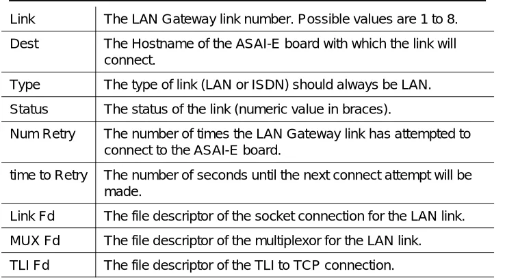
If the connectivity fails for LAN type links, use the link_status(1)
command to obtain the current status of LAN link(s).
If the status is other than Talking, use the ping command to verify connectivity to the host; for example, /usr/sbin/ping hostname
where hostname is the hostname of the MAPD administered in Step 13.
If the ping command returns an affirmative response yet asai_test fails, check the /usr/adm/isdn/lan_parms file for typographical errors. If there are none, verify that the MAPD administration is correct by following the procedures in the DEFINITY ECS CallVisor ASAI DEFINITY LAN Gateway over MAPD Installation, Administration, and Maintenance, for your operating system.
If the ping command returns a negative response, either the ASAI MAPD is not properly configured, not connected to the LAN or there may be other LAN problems (for example, LAN administration or routing). Consult the
DEFINITY ECS CallVisor ASAI DEFINITY LAN Gateway over MAPD Installation, Administration, and Maintenance and the Network Administrators’ Manual for these types of problems.
If the DEFINITY ECS and ASAI MAPD are properly administered and the LAN checks out, call the CallVisor PC helpline number at
1 732 957-5725.
If the connectivity test succeeds, you have demonstrated the compatibility of the computing platform and the CallVisor PC package.
Installation
ISDN links are installed and a default value of 1024 if any LAN GATEWAY links are installed. This should be sufficient for the majority of applications using ASAI.
However, if the adjunct processor has a limited amount of memory or if a running ASAI application is controlling a large number of stations or calls, NCLID may need to be changed. In any case, NCLID should be set to conform to your system’s specific operational needs. For more details, see ‘‘Configuration’’ on page 1-18 of this chapter.
You can install the CallVisor PC ITT package at any time. Enter the command:
pkgadd -d diskette1
Place the CallVisor PC ITT product disk in the appropriate drive and follow the online instructions.
Pkgadd displays that the CallVisor PC ITT package is available to process.
Press to continue installation.
After the installation procedure is complete, remove the diskette from the disk drive. The message Installation of <cvitt> was
successful is displayed.
CV/LAN Product Description
CV/LAN allows application software running on UnixWare, Solaris x86, SPARC Solaris™, or Windows NT 4.0 to access the DEFINITY ECS CallVisor ASAI features across a TCP/IP LAN in a client-server arrangement.
The server runs on the CallVisor PC or the Multi-Application Platform for DEFINITY (MAPD). The CallVisor PC and CV/LAN applications use the same library and differ slightly in only one API call. For further information see Chapter 6, ‘‘CV/LAN Programming.’’
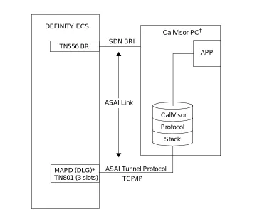
The following Figure 1-1 shows how the applications run on the CallVisor PC server and connect to the DEFINITY ECS through the DEFINITY LAN Gateway ethernet interface, or through an ISDN-BRI interface.
DEFINITY ECS
ISDN BRI
ASAI Link
MAPD (DLG)* TN801 (3 slots)
* MAPD Board Running the DEFINITY LAN Gateway Application † UnixWare or Solaris X86
CallVisor
Protocol
Stack
ASAI Tunnel Protocol
CallVisor PC†
TCP/IP TN556 BRI
Installation
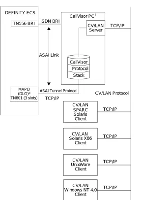
The following Figure 1-2 shows how CallVisor PC is configured as a CV/LAN server. Applications can run on all the connected CV/LAN clients. Connectivity to the DEFINITY ECS is provided through the CallVisor PC server over either a DEFINITY LAN Gateway Interface, or an ISDN-BRI interface. The CV/LAN clients do not communicate directly with the ECS.
Figure 1-2. CallVisor PC as a CV/LAN server
MAPD (DLG)* TN801 (3 slots) DEFINITY ECS ISDN BRI ASAI Link SPARC Solaris TCP/IP TCP/IP TCP/IP TCP/IP TCP/IP CV/LAN Solaris X86 CV/LAN UnixWare Client CV/LAN Windows NT 4.0
Client Client
Client
* MAPD Board Running the DEFINITY LAN Gateway Application † UnixWare or Solaris X86
CallVisor Protocol
Stack
CV/LAN Server
ASAI Tunnel Protocol
CallVisor PC†
CV/LAN TCP/IP
TN556 BRI
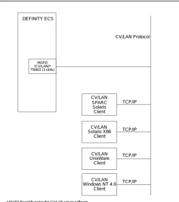
The following Figure 1-3 shows that ASAI client application communication is done directly through TCP/IP to the MAPD running CV/LAN server software (PEC 1273-CVL). It does not involve any CallVisor PC server.
Figure 1-3. CallVisor PC Configuration — CV/LAN to MAPD
CV/LAN client is supported over the following platforms: UnixWare 2.1.2 and later; Solaris x86, SPARC Solaris versions 2.4, 2.5, 2.5.1, and Windows NT 4.0. The
DEFINITY ECS
SPARC Solaris
TCP/IP
TCP/IP
TCP/IP
TCP/IP CV/LAN
Solaris X86
CV/LAN UnixWare
Client
CV/LAN Windows NT 4.0
Client Client
Client
MAPD
* MAPD Board Running the CV/LAN server software
CV/LAN
CV/LAN Protocol
Installation
System Configuration
Each client communicates with the server through any Ethernet interface card supporting Unixware versions 2.1.2, and later; Solaris x86, SPARC Solaris versions 2.4, 2.5, 2.5.1, as well as Windows NT 4.0. Application software on the clients has access to the full range of ASAI features supported by the CallVisor PC ASAI interface.
The CV/LAN server runs on UnixWare 2.1.2 and later, and Solaris x86 operating systems; it requires the CallVisor PC ASAI library package. The interface card between the server and the DEFINITY ECS may consist of the PC/ISDN-BRI card or the DEFINITY ECS LAN Gateway card. The server communicates with clients over the LAN through any Ethernet interface card supporting Unixware or Solaris x86.
Software Configuration
The CallVisor PC ASAI library must also be installed on the client side. Client administration specifies a “well known address” to access a server. In addition to UNIX, the server must be running the CallVisor PC ASAI library package and CV/LAN server software.
System Operation and Limits
Client applications use the CV/PC ASAI library to establish communication with a server. This process is nearly identical to that used with the CallVisor PC ASAI library (server addresses must be specified by the client; this is not required in the PC ASAI library). Once a connection is established, the applications use library routines asai_send() and asai_rcv() to send and receive ASAI messages. The server routes the messages to and from the proper DEFINITY ECS. The format of the messages matches exactly those used with the CallVisor PC/ASAI library. Except for minor changes in the communication establishment,
asai_open expects that the applications developed with the CallVisor PC/ASAI library will run unchanged over the LAN.
Server Installation on UNIX
For the CV/LAN, UNIX Platform refers to both Unixware and Solaris x86.
The CV/LAN server can only be installed after CVISDN and CVASAI have been installed.
1. To install the CV/LAN server, type the command:
pkgadd -d diskette1
2. Place the Lucent Technologies CallVisor PC CV/LAN Server disk in the appropriate drive and follow the online instructions. Pkgadd displays that the package is available to process. Press to continue the installation.
After the installation procedure is complete, the installation program asks you to remove the diskette from the disk drive. Shutdown instructions and the message
Installation of <cvlansrv> was successful, are also displayed.
Client Installation on UNIX
You can install the PC CV/LAN Client package at any time.
1. Enter the command:
pkgadd -d diskette1
2. Place the PC CV/LAN Client disk in the appropriate drive and follow the online instructions.
3. Pkgadd displays that the PC CV/LAN Client package is available to process. Press to continue the installation.
4. After the installation procedure is complete, remove the diskette from the disk drive. The message Installation of <cvlanxcl> was successful, is displayed.
Client Installation on Windows NT
1. To install the CV/LAN Client on a Windows NT 4.0 system, insert the Client diskette in drive A.
2. Click on the RUN File Menu Item under Program Manager or File Manager, type Setup in the dialog box, and press OK.
RETURN
Installation
NOTE:
After the Setup is complete, CV/LAN.DLL, the dynamic link library and CV/LAN.LIB, the import library, will be installed under a subdirectory called
Program.
Running the Sample Application
To run the application on UNIX, the command is itt <script-name>.
DEFINITY ECS Administration
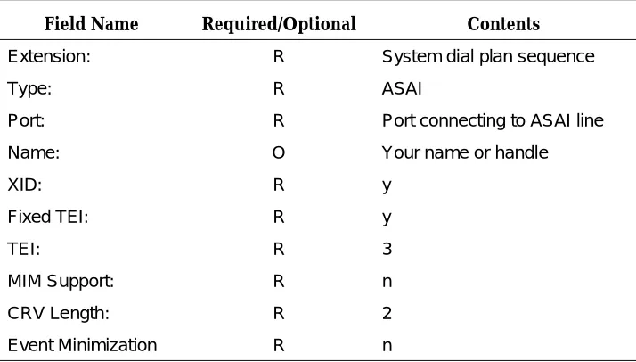
The DEFINITY ECS BRI line must be administered to establish ASAI connectivity between the DEFINITY ECS and the adjunct computer. Use the add station or
change station command to administer the BRI line. Use the following table as a guide.
The Type, XID, Fixed TEI, TEI, MIM Support and CRV Length fields all must have the indicated required contents in order to match the built in administration of the IPCI board and CallVisor PC ASAI software.
The ISDN protocol stack, specifically the QP module, supports version selection. Version 1 (default) corresponds to G3V3, Version 2 corresponds to G3V4 and Version 3 corresponds to the DEFINITY ECS Release 6. For Release 63, the default also is 3. To find out which software version is on the DEFINITY ECS, use the list conf soft command. The Software Version is displayed on the Memory Resident: line.
Table 1-1. Field Name and Requirements
Field Name Required/Optional Contents
Extension: R System dial plan sequence
Type: R ASAI
Port: R Port connecting to ASAI line
Name: O Your name or handle
XID: R y
Fixed TEI: R y
TEI: R 3
MIM Support: R n
CRV Length: R 2
Installation
Configuration
This section assumes that you have read the installation steps in this document.
NOTE:
The Network Support Utilities (NSU) package must be installed before you can install the CallVisor software packages.
The NSU package contains the streams utilities, header files, libraries and other files that are needed to add streams modules to the UNIX system kernel.
Upgrading Software
The upgrade procedure consists of removing the existing packages and installing the new packages as described in ‘‘DEFINITY ECS Administration’’ on page 1-17 of this chapter. Upgrade the system when no one else is using the computer.
You must supply the configuration information as part of the upgrade procedure.
NOTE:
Before beginning the upgrade, copy or print the current configuration parameters for future reference.These parameters can be found in the files
/usr/adm/asai/asai_parms and /usr/adm/isdn/ipci_parms.
1. Log in as root. Bring the computer to single-user mode and then run state 1 by entering the command:
shutdown -iS -y -g120
2. Press Ctrl-d to proceed and enter 1 for the selected run state.
3. Remove the CallVisor PC software by entering the commands:
pkgrm cvasai and pkgrm cvisdn
4. Now install the new version. Configure the software as described in the ‘‘Configuring and Reconfiguring Software’’ on page 1-19 of this chapter.
Removing Software
To remove software, enter the command:
pkgrm cvasai
and
pkgrm cvisdn
and
pkgrm command removes all package-created and installed files, along with
directories created when the package was installed.
When you execute pkgrm cvasai, all files in the /usr/adm/asai directory, along with all other files belonging to the ASAI package, are removed.
Also, for isdn package, when you execute pkgrm cvasai, all files in the
/usr/adm/isdn directory, along with all other files belonging to the ASAI package, are removed.
All ASAI header files installed in /usr/include/asai and ISDN/IPCI headers for the ISDN package in the /usr/include/isdn directory are removed. The directories are removed only if they are empty.
NOTE:
If you have local header files or other files in these directories, they will not be removed and neither will the directory.
The pkgrm procedure will build a new UNIX kernel. When this is completed, a message will be displayed requesting to reboot the system. After both packages have been removed, execute the command
shutdown -i6 -y -g0
to reboot the system.
Configuring and Reconfiguring Software
The initial part of the installation and upgrade procedure consists of configuring the software. You must enter the information when prompted by the software. See the ‘‘Configuration’’ on page 1-18 of this chapter for more details. For the ISDN package, you must enter the number of IPCI boards to be installed or those already installed, the IRQ number, the PC memory addresses as well as the matching version parameters. Refer to the table below for default IPCI values:
Table 1-2. Default IPCI Configuration Values
ISDN board # IRQ/IVN PC memory address
1 2 d0000
2 2 d4000
3 2 d8000
Installation
Note that regardless of the number of ISDN boards installed in the computer, the same IRQ/IVN number is used. Matching Versions Requirement for the ISDN protocol stack, specifically for the QP module, must be done correctly or the ASAI link will not come up. Three new tunable parameters are provided to allow selecting the desired version and allowable alternatives. QP_DESIRED is set to the desired version. Version 1 corresponds to G3V3, Version 2 corresponds to G3V4 and Version 3 corresponds to the DEFINITY ECS Release 6. For Release 64, the default also is 3. QP_HIGHERVER and QP_LOWERVER are provided to allow higher version and/or lower version operation.
The tunable parameters are located in /etc/conf/cf.d/stune. The defaults are:
QP_DESIRED_VER is set to 3 (Release 6)
QP_HIGHERVER is set to 3 to allow higher (later) versions QP_LOWERVER is set to 1 to allow lower (earlier) versions
If you have to reconfigure your adjunct computer system (to change the version, for example), do so when no one else is using the adjunct.
To change the values, edit the /etc/conf/cf.d/stune file. Follow the standard tuning procedures and rebuild the kernel, then reboot the system. Execute the command
shutdown -i6 -y -g0
to reboot the system.
If the version parameters are incompatible with the ECS version, the BRI link will not start up. The QP module will log this error to the system console and the crash buffer.
For the ASAI package, you must enter the number of ASAI nodes/IPCI boards installed: 1, 2, 3, or 4 (if that information is not available at the time of installation). If the ISDN package was installed first, this information is available to the ASAI package.
If only one IPCI board was configured for the ISDN package, the following message is displayed:
Configuring <cvasai> for 1 ASAI Nodes.
Reconfiguring the packages requires you to reinstall the ISDN and ASAI software.
If you have to reconfigure your adjunct computer system (to add a board, for example), do so when no one else is using the adjunct.
NOTE:
Make sure that you save a copy of the current configuration parameters for future reference.
Memory Considerations
This section introduces a number of concepts that assume practical experience with administration of the ASAI applications package. The material presented here is discussed in detail in Chapter 1, “ASAI and Capability Groups” of
DEFINITY Enterprise Communications Server Release 6 CallVisor ASAI Technical Reference.
ASAI services are broken down into functional sets called capability groups. Capability groups enable the adjunct to communicate and control the DEFINITY ECS. Central to the idea of capability groups and ASAI in general is the concept of an association.
An association is a channel of communication between the adjunct and the DEFINITY ECS that is used for messaging purposes. An association begins with initiating capabilities, controlling capabilities manipulate messages during an association and terminating capabilities end an association.
An adjunct or more specifically, each BRI board installed on an adjunct, can manage many active associations at one time and each association must be tracked by the CallVisor ASAI software drivers. Tracking consumes adjunct memory that must be reserved for the CallVisor drivers (148 bytes are required to track a single association).
The amount of memory to be reserved is specified by the NCLID (number of cluster ids) environment variable. NCLID effectively limits the number of active ASAI associations that are allowed to run on each BRI board. It is important to note that the NCLID specifies the maximum number of associations that may run on each BRI board, not the maximum number for all boards combined.
The NCLID default is 2048. This should be sufficient for the majority of
applications using ASAI. However, if the adjunct processor has a limited amount of memory, or if the ASAI application is controlling a large number of stations or calls, the NCLID will need to be adjusted. In any case, the NCLID value should always be set to conform to your system’s specific operational needs.
Installation
NCLID reduces both the number of active associations and the amount of adjunct memory reserved for each board.
For instance, setting the NCLID to 1024 reduces the number of active associations per board to 1024 and cuts the amount of reserved memory per board to 148K (1024 x 148). Alternately, setting the NCLID to 512 reduces the number of active associations per board to 512 and cuts the amount of reserved memory per board to 74K (512 x 148). These settings are not likely to impact the performance of most applications.
Certain ASAI applications may require the NCLID to be increased above the default of 2048. If the ASAI application is using one ASAI link to control a large number of calls on a R5r, the NCLID may need to be increased. There is, however, a practical limit to which the NCLID value may be raised. Appendix B “ASAI and Release 6 Requirements” of DEFINITY ECS Release 6 CallVisor ASAI Technical Reference discusses the capacity requirements and constraints for the DEFINITY ECS Release 6 in detail.
For example, Table B-1 of that appendix lists all the R5r systemwide ASAI limits for the maximum number of domain-control station associations as 6000. However, setting the NCLID to a value between the default (2048) and the maximum (9600), (for example 5000), will not always guarantee that 5000 active ASAI associations can be supported.
Despite the fact that the theoretical maximum number of domain-control station associations is 6000, the actual maximum number of associations is limited by the availability of a variety of other system resources.
For this reason, you must consider several factors when setting the NCLID in the hope of maximizing performance. The amount of memory available on the adjunct processor, as well as the number of BRI boards installed, greatly affect system capabilities.
It must also be noted that the capacity requirements and constraints on the DEFINITY ECS Release 6, apply equally to all ASAI links. If an application uses more than one ASAI link or if other ASAI applications are connected to the same DEFINITY ECS, the maximum number of associations per link will be lower than normal. This will also affect the actual maximum number of associations that can be realized.
Set NCLID using the idtune(1M) command. Follow the procedures outlined in
Starting Up the System
System start-up for CallVisor PC ASAI is automatic. When you boot the adjunct, the asai_admin daemon is started. asai_admin completes the protocol stack and begins the process of message writing to the asai_log. If there is an existing log, it is moved to old_asai_log.
The asai_log contains messages about the start-up process. The sample below shows typical log entries for a successful start-up.
910318165042:asai_admin: ASAI administration daemon has started.
910318165042:asai_admin: Push of FEL onto /dev/isdn/ipci/signal01 succeeded. 910318165042:asai_admin: Link of /dev/asai/asai file with /dev/isdn/ipci/signal. 910318165042:asai_admin: l01 succeeded.
910318165042:asai_admin: ASAI stack setup was successful.
2
OA&M
The ASAI Log File
The ASAI log file, asai_log, is stored in /usr/adm/asai and can be examined using vi or cat.
Each time the UNIX system is started, the existing log file is moved to
old_asai_log and a new log file is created. This old_asai_log file is located in the same directory as asai_log. In addition, if asai_log becomes “full” (close to ulimit in size), it is moved to old_asai_log. Note that this overwrites an existing old_asai_log.
You can split or copy a log file; however, only root has write permission in the
/usr/adm/asai directory. Therefore, you will have to use a directory in which you have write permission to execute the split or cp command. (The ASAI Administration menu provides access to UNIX system commands, so you can do this by escaping from the menu, if you prefer.)
The log file contains entries consisting of a date and time stamp followed by a colon, the name of the ASAI process that wrote the message, another colon and the message. The message tells you whether or not the process executed successfully.
Figure 2-1. An ASAI Log File
In the sample shown above, the first 12 characters represent a date and time stamp. The date is in the form yymmdd; the time is in the form hhmmss, based on a 24-hour clock. Thus 11:30 p.m. appears as 2330.
Following the date and time stamp, comes the name of an ASAI process, preceded by a colon (asai_admin in the sample). Another colon precedes the message. Messages longer than 53 characters are carried over to the next line as shown in lines 2 and 3 in Figure 2-1.
910318165042: asai_admin: ASAI administration daemon has started. 910318165042: asai_admin: Push of FEL onto /dev/isdn/ipci/signal01 succeeded.
910318165042: asai_admin: Link of /dev/asai/asai with /dev/isdn/ipci/signal.
910318165042: asai_admin: 101 succeeded.
OA&M Manual Pages
This section contains manual pages for the commands and files that comprise ASAI Operations, Administration and Maintenance (OA&M). For ease of reference, commands, and files appear in alphabetical (ASCII) order.
In this section (1) corresponds to commands, (4) refers to the files, and (7) corresponds to the devices and pseudo-devices.
Command name prefixes and suffixes imply the following:
admin(7) ipci_off(1) asai(4) ipci_on(1) asai(7) ipci_stat(1) asai.Date(4) ipci_test(1) asai.Name(4) ipci_ver(1)) asai_admin(1) isdn_alarm(1) asai_cause(1) isdn.Date(4) asai_hb(1) isdn_l1_r(1) asai_log((4) isdn_l2_r(1) asai_test(1) isdn.Name(4) asai_trace(1) isdn_trace(1) asai_ver(1) lan_status(1) boot.bin(4) log_msgs(4) cmd(7) link_alarm(1) command(7) link_offline(1) esai_alarm(1) link_restart(1) esai_trace(1) link_status(1) ipci_admin(1) pcisdn.bin(4) ipci_init(1) signal(7)
asai_ Commands related to the kernel ASAI protocol stack or the ASAI library
ipci_ Commands related to the ipci device drivers
isdn_ Commands related to the BRI link between the BRI board and the ECS
.bin Commands related to software that is downloaded (‘‘pumped”) to the BRI board
esai_ Commands related to the CallVisor LAN GATEWAY interface
OA&M
admin(7)
Name
admin — IPCI and LAN GATEWAY Streams Device Driver Communication File
Description
The admin file allows communication between the ipci_admin(1) program, the IPCI streams device driver and the LAN GATEWAY streams module. The IPCI streams device driver communicates with the IPCI board and with software on the board.
This file is meant to be used only by the ipci_admin(1) program. Information flows only one way from the IPCI device driver to the ipci_admin(1) program.
This file will have the same major device number as the signal(7) and command(7) files. Its minor device number is 0.
Files
/dev/isdn/ipci/admin /dev/esai/admin
See Also
asai(4)
Name
asai — Start ASAI administration
Synopsis
asai
Description
asai is a shell script that starts the ASAI administration daemon process,
asai_admin(1), located in /etc/idrc.d.
Operation
The asai program is executed once per machine boot in the multiuser init level 2. The name of the log file (asai_log) is changed to old_asai_log. The administration daemon asai_admin(1) is then started. When this is done, the standard error device is defined as /dev/console for asai_admin(1).
Files
/usr/adm/asai/asai_log
See Also
asai(7)
OA&M
asai(7)
Name
asai — ASAI communication file
Description
This file allows co