Aseismic Design of Structure-Equipment Systems Using Variable Frequency
Pendulum Isolator
Sinha Ravi 1) and Murnal Pranesh 1)
/
1) Department of Civil Engineering, Indian Institute of Technology Bombay, Powai, M u m b a i - 400 076, India
ABSTRACT
Several sliding isolation systems such as friction pendulum system (FPS) have emerged as very useful vibration control systems incorporating isolation, energy dissipation and restoring mechanism in one unit. However, these systems often have practical limitations and are not very effective when the input excitation level is significantly different from the designed level. To overcome these limitations while preserving the advantages, a new system called the variable frequency pendulum isolator (VFPI) has been developed by the authors. The natural period of VFPI varies with horizontal sliding displacement leading to a more robust isolation system. In this paper, it has been shown that isolating a structure using VFPI is very effective for vibration control of structure-equipment and other similar primary-secondary systems. An example five-storey shear structure with equipment mounted at its top has been analysed to demonstrate the effectiveness of VFPI. It is found that VFPI provides better performance compared to other friction isolation systems, and excellent response reduction is observed for a wide range of equipment properties.
I N T R O D U C T I O N
Use of base isolation systems has emerged as a very effective technique for aseismic design of structures. In base isolation technique, a flexible layer (or isolator) is placed between the structure and its foundation such that relative deformations are permitted at this level. Since the isolator is flexible, the time period of motion of the isolator is relatively long compared to that of the structure and the isolator time period governs the fundamental period of isolated structure. For properly designed isolation systems, the isolator time period is much longer than those containing significant ground motion energy. As a result, use of isolator shifts the fundamental period of the structure away from predominant periods of ground excitation thereby decreasing the energy introduced into the structure. Extensive review of base isolation systems and its applicability is available in literature [ 1, 2].
Isolation systems that use a sliding layer incorporate isolation and energy dissipation in one unit since energy is dissipated through friction during sliding. Such systems are very effective in controlling the vibrations of structures due to earthquake and their behaviour is relatively independent of frequency and amplitude of ground motion [3]. However friction systems that use a horizontal sliding surface (Pure-Friction System) typically experience large sliding and residual displacements that are difficult to incorporate in structural design. A modified isolation system called the friction-pendulum system (FPS) has been extensively used in which the sliding and re- centring mechanisms are integrated in one unit and the sliding surface takes a concave spherical shape [4]. The FPS isolators have many advantages over pure friction system; however, severe practical difficulties of aseimsic design using FPS isolator due to its fixed time-period have also been observed [5].
The authors have recently developed a new isolator called the Variable Frequency Pendulum Isolator (VFPI), in which a progressive period lengthening takes place with increase in sliding displacement, and which also has a restoring force softening mechanism [6, 7]. The performance of VFPI has been found to be very good under a variety of earthquake excitations and useful for many different applications [8, 9]. In the present paper, the performance of VFPI for aseismic design of structure-equipment system has been discussed. The basic mathematical formulations of structure and equipment response have also been shown. The response of a multi-storey shear building-equipment system isolated with VFPI has been evaluated for different intensities of earthquake excitations. The results have been compared with the response obtained for fixed base structure, and structure isolated by FPS and Pure-Friction (PF) isolators. It is found that a substantial reduction in the equipment response can be achieved by isolating the structure with VFPI, when compared to other systems.
V F P I G E O M E T R Y
Consider a rigid block of mass m sliding on a curved surface of any geometry, y =
f(x)
representing the sliding surface of the isolator. The origin of the surface is at the centre where the sliding displacement is zero. At any instant the restoring force is given by,SMiRT 16, Washington DC, August 2001 Paper # 1306
dy
fR = m g ~ (1)
dx
Assuming that this restoring force is provided by an equivalent spring, the spring force can be expressed as the product of spring stiffness and spring deformation. The spring stiffness in turn may be expressed as product of mass and square of isolator frequency. So,
f R = mco~ ( x ) x (2)
where, co b (x) can be called the instantaneous isolator frequency, which solely depends on geometry of the sliding
surface. In case of the FPS that has spherical sliding surface, the isolator frequency is approximately a constant and the restoring force is linear. The geometry of sliding surface of Variable Frequency Pendulum Isolator is derived from the basic equation of an ellipse, with its major axis being a linear function of sliding displacement [6]. The geometry can be represented as
~/d 2 +
2dx sgn(x) ]y = b 1 - (3)
d + x sgn(x)
The slope at any point on the sliding surface is given by
dy bd
= . x (4)
dx (d + xsgn(x))2~/d 2 + 2dx sgn(x)
Defining r = x s g n ( x ) / d and the initial frequency when x = 0 asco 2 : g b / d 2 , the instantaneous frequency can be expressed as
2
~ ( x ) : ~ ' (5)
(1 + r) 2 ~/1 + 2r
In the above equations, parameters b and d completely define the isolator properties. The ratio b i d 2 decides the initial frequency of the isolator and the value of d decides the rate of variation of the isolator frequency. Accordingly the factor 1/d is termed as Frequency Variation Factor (FVF). The rate of variation of isolator frequency with sliding displacement is directly proportional to FVF.
The VFPI has two distinguishing characteristics that makes it more effective than the other friction type isolators: (1) The isolator frequency decreases with increase in sliding displacement so as to provide frequency separation between the structure and the excitation and (2) The isolator restoring force has softening mechanism for large sliding displacements which limits the maximum force that is transmitted to the structure during high levels of excitation thereby providing fail-safe mechanism [6, 7].
M A T H E M A T I C A L F O R M U L A T I O N
The mathematical formulation has been given below for an N-storey shear building isolated by VFPI, although the formulation can be easily extended for general 3-dimensional structures. Due to the action of frictional forces at the sliding surface, the motion consists of two phases namely, non-sliding phase and sliding phase. The equations of motion are different in the two phases and the overall behaviour consisting of a random series of sliding and non-sliding phases is highly non-linear. Depending on the phase of motion, the corresponding equations govern the response of structure and equipment.
N o n - s l i d i n g P h a s e
In this phase the structure behaves as a conventional fixed base structure. Due to the frictional resistance there is no relative movement between the base mass and the ground. The equations of motion governing this phase are,
and
JCb = )~b = 0 and Xb = c o n s t a n t (7)
with
< mt/-z g ( 8 )
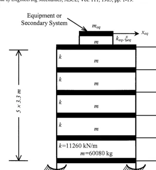
In the above equations, M, C and K are the N x N mass, damping and stiffness matrices of the structure (excluding base mass), respectively, x is the vector of relative displacements of the structure with respect to the base mass, Xb is the sliding displacement of isolator, r the force influence vector, rni is the mass of the ith floor, rnb is the base mass and m t the total mass of the structure (Fig. 1). The coefficient of friction is given b y / 1 and the dots indicate derivative with respect to time. The left-hand side of Eq. (8) is the absolute value of sum of the total inertia force and the restoring force at the isolator level and the right hand side is the frictional force that must be overcome for sliding motion to take place.
Sliding Phase
The structure starts sliding when the forces on the system exceed the static frictional force leading to motion of the base mass. The structurenow has one additional degree-of-freedom. The equations of motion are given by,
MJ~ +C/¢ + Kx = - M r ( Y b + Yg)
(9)
for the structure, and
mi(Jci + JCb + Xg ) + mb(JCb + Xg ) + mtCO2bXb + mtAlgsgn(xb ) = 0 i=1
(10)
for the base mass; where, sgn(k b) is the signum function, which assumes a value of +1 for positive sliding velocity and -1 for negative sliding velocity. This value is determined from the sign of the sum of total inertia force and isolator restoring force given below [5].
E"
Z rni(Jci + Xb + JCg) + mb(JCb + Xg)+ rnt(O2bXb]
sgn(kb) = - i=1 (11)
IE"
Z mi(Jci + JCb + JOg) + mb(SCb + 5ig)+ mt(_O2bXb1
i=1
The value of signum function remains constant in a given sliding phase. The end of a sliding phase is governed by the condition that the sliding velocity of the base is equal to zero, i.e.,
k 6 : 0 (12)
As soon as Eq. (12) is satisfied, Eq. (6) and (7) corresponding to the non-sliding phase are to be used to evaluate the response quantities and check the validity of inequality in Eq. (8). This decides whether, during the next time step, the structure continues in the sliding phase or enters a non-sliding phase.
RESPONSE OF ISOLATED STRUCTURE-EQUIPMENT SYSTEMS
to those of the primary structure, such as frequency ratio (ratio of frequency of secondary system to the fundamental frequency of the primary system), mass ratio (ratio of mass of the secondary system to the mass of the primary system) and damping in the secondary system [ 10]. The secondary systems exhibit highly amplified responses when the frequency ratio is nearly equal to unity. Isolating the primary system changes the dominant frequency of excitation at the base of the secondary system as well as reduces excitation amplitude.
In the present investigations the response of a light equipment mounted on top of an example shear structure has been considered. The structure consists of a five-storey shear building (excluding base degree of freedom), 5m square in plan (Fig. 1). The storey stiffness has been taken as 112600 kN/m, and the floor mass has been chosen such that the fundamental frequency of the fixed-base structure is close to the predominant frequency of E1 Centro ground motion (approximately 2.0 Hz). The different storeys, including the base mass, have equal mass of 60080 kg. The investigations are carried out for E1 Centro ground motions with two different scaling or intensity factors: (1) intensity factor of 1.0, i.e. original recorded ground motion, and (2) intensity factor of 2.0, i.e. accelerations intensified by a factor of 2 to represent very high intensity earthquake. The natural frequencies and effective modal mass of the fixed base structure and the structure isolated by VFPI are shown in Table 1. It should, however, be kept in mind that frequencies of a structure isolated by VFPI change continuously with isolator displacement. The frequencies shown in the Table 1 indicate an upper bound on the frequencies that is obtained when the isolator displacement is zero. A light equipment, that has a mass of 1% of the total mass of the structure (including the base mass), is placed on the top storey. The equipment has been modelled by a mass with linear spring and a damper attached to the top floor of the structure. The structural and equipment damping are both assumed to be equal to 5% of critical damping to eliminate the influence of non-classical damping from this evaluation. The parameters of VFPI are chosen as b - 0.01 m, d = 0.10 m and FVF of 10 per m so that it has initial time period of 2.0 sec and the frequency reduces very sharply with sliding displacement. The coefficient of friction has been taken as 0.02. The secondary system has a mass of 1% of the total mass of the structure (including the base mass) and is attached to the top storey.
Table 1. Modal properties of fixed base and isolated structure without equipment
Mode Number
Fixed-base- Frequency (Hz)
Effective Modal Mass (%)
Isolated Frequency (Hz)
Effective Modal Mass (%)
Isolator
0.49
99.93
1.96
87.95
3.64
0.07
5.72
8.72
6.92
0.00
9.02
2.42
9.76
0.00
11.59
0.75
11.93
0.00
13.22
0.16
13.31
0.00
Table 2. Peak acceleration (g) of equipment with frequency tuned to the natural frequencies of the isolated structure
Equipment frequency (Hz) 3.73 7.14 10.00
Structure Isolated by FPS 0.635 0.510 0.368
Structure Isolated by VFPI 0.440 0.353 0.328
12.50
0.306
0.262
Time-History Response
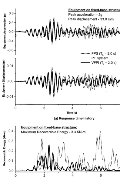
The typical time-history for recoverable energy of equipment (kinetic energy + strain energy) [5] is shown in Fig. 2(c). This result gives additional information, which cannot be obtained from the response time-history. From this plot it is observed that the maximum recoverable energy in equipment is considerably reduced when structure isolated by VFPI in comparison to that isolated by FPS. However, as expected, it is higher than that of a PF system. As the absolute kinetic energy has been considered, the effect of rigid body movements is implicitly included, which is manifested through the various peaks in the energy time-history for FPS isolated structure. These peaks are also drastically reduced in case of VFPI and PF systems indicating more stable response of the equipment.
Floor Response Spectra of Equipment
The maximum response of single-degree-of-freedom equipment can be conveniently studied in terms of its floor response spectra. The floor response spectra enable one to evaluate the effectiveness of various isolation systems for secondary systems with different properties.
The displacement and acceleration floor response spectra have been shown in Fig. 3. The effects of structure-equipment interaction, including the effect of equipment on structure, are fully considered in the analysis. The displacement spectra are normalised with respect to the peak displacement of equipment mounted on fixed-base structure (equal to 0.28 m). In case of a fixed-base structure the equipment acceleration response is maximum when the equipment frequency tunes with fundamental frequency of the structure (approximately 1.85 Hz). However for base-isolated structures, the first natural frequency is the isolator frequency, which is much lower than that of both the fixed-base structure and the equipment. So, the possibility of equipment frequency tuning with the isolator frequency is very unlikely and has not been included. The equipment response shows a peak when the equipment frequency is close to the second frequency of the isolated structure. This can be clearly observed from the acceleration spectra (Fig. 3(b)) wherein the peak in FPS occurs at 3.85 Hz, which is close to the second isolated frequency (see Table 1). It is to be noted that the amplification of response due to tuning is almost non-existent in case of VFPI. This is due to variation in frequency of VFPI with sliding displacement, which constantly changes fundamental frequency of the isolated structure. It is further observed that response of equipment mounted on structure with VFPI performs better for the entire range of equipment frequencies. The VFPI is effective even for flexible equipment whereas a conventional FPS shows higher response.
The maximum equipment acceleration when its natural frequency is tuned to the natural frequencies of the isolated structure is shown in Table 2. It has been found that for all frequencies of equipment, the use of VFPI for isolating the structure is more effective in reducing the response than the use of FPS. This is due to the almost constant fundamental period of structure isolated by FPS wherein the structure behaves like a narrow banded filter. On the other hand the fundamental period of a structure isolated by VFPI continuously changes with sliding displacement, making it behave as a wide band filter and providing better vibration control.
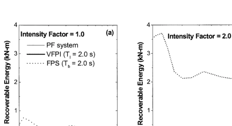
The floor-response spectra of recoverable energy for medium and high intensity excitations are shown in Fig. 4. For both excitations there is a substantial reduction in the peak equipment response for VFPI-isolated structure than that for FPS-isolated structure. It is interesting to note that the recoverable energy in equipment on FPS-isolated structure increases with intensity of excitation, whereas the energy in equipment on VFPI-isolated structure and PF isolated structure is relatively independent of intensity. It is also seen that the variation in equipment response with its frequency is very small when the structure is isolated using VFPI. This shows that the performance of secondary system or equipment is relatively independent of the frequency content and amplitude of excitation when structure is isolated by VFPI. The use of VFPI for structure isolation therefore also acts as a very effective device for passive vibration control of secondary systems.
CONCLUSIONS
The mathematical formulation for response of structures isolated using the Variable Frequency Pendulum Isolator (VFPI) has been presented in this paper. The VFPI provides the ability to vary isolation time period with sliding displacement thereby eliminating the possibility of tuning between the structure and isolator or between the isolator and ground motions. The response of equipment mounted on structures isolated using VFPI and other isolators have been evaluated to evaluate the effectiveness of VFPI. Based on this investigation following conclusions can be drawn:
1. The VFPI is a robust isolation device and is very effective in controlling the response of equipment placed on VFPI isolated structure compared to the same equipment placed on structure isolated by other friction isolators.
2. The VFPI is effective in vibration control of equipment with wide range of modal properties.
REFERENCES
1. Buckle, I. G. and Mayes, R. L., "Seismic isolation: history, application and performance - a world view," Earthquake Spectra, EERI, Vol. 6, 1990, pp. 161-201.
2. Naeim, F. and Kelly, J. M., Design of Seismic Isolated Structures." From Theory to Practice, John Wiley and Sons, New York, NY, 1999.
3. Mostaghel N. and Tanbakuchi, J., "Response of sliding structures to earthquake support motion," Journal of Earthquake Engineering and Structural Dynamics, Vol. 11, 1983, pp. 729-748.
Zayas, V. A., Low, S. S. and Mahin, S. A. A simple pendulum technique for achieving seismic isolation, Earthquake Spectra, EERI, Vol. 6, 1990, pp. 317-333.
5. Pranesh, M., VFP1: An Innovative Device for Aseismic Design, Ph.D. Thesis, Indian Institute of Technology, Bombay, 2000.
6. Pranesh, M., and Sinha, R, "VFPI: an isolation device for aseismic design," Journal of Earthquake Engineering and Structural Dynamics, Vol. 29, 2000, pp. 603-627.
7. Pranesh, M. and Sinha, R., "Earthquake resistant design of structures using VFPI," Journal of Structural Engineering, ASCE, submitted paper, 2001.
8. Pranesh, M. and Sinha, R., "Aseismic design of tall structures using Variable frequency pendulum isolator." Proc. of 12 th World Conference on Earthquake Engineering, Auckland, New Zealand, Paper No. 284, January 2000.
Sinha R. and Pranesh M., "FPS isolator for structural vibration control," Proc. of International Conference on Theoretical, Applied, Computational and Experimental Mechanics, Kharagpur, India, December 1998. 10. Igusa, T. and Der Kiureghian, A., "Dynamic characterisation of two-degree-of-freedom equipment-structure
system," Journal of Engineering Mechanics, ASCE, Vol. 111, 1985, pp. 1-19.
.
.
Equipment or
Secondary S y s t e m ~ _ m
~ ~ l l l " - - - " - ~
Xeq
keq, 4eq
me~
re5
k
m
m
m
m
k = 11260 kN/m m=60080 kg
X4
-...~Xb
[I
5m
".]
1"
"1
.-. 0.8 O 3
r -
O
= E 0 4 - •
,,,,,=
u
o.o r -
E -0.4
o . =
13" III
-0.8
-
= 0.011
EU O .
i5 0 . 0 0
o , u
" ' - 0 . 0 1
,~, 0 . 4
>' 0 . 3 =~
U J ¢~ 0 . 2
8
0.10 . 0
E q u i p m e n t o n f i x e d - b a s e s t r u c t u r e :
P e a k a c c e l e r a t i o n - 2 g
e 0is0, cemeot- .Smm
_ , , ,
^ ^ ,~ A
, ~ ~
A a-,,~,u'n ~l~^',~,rt ~,/ti
,", ",-
, ,, " ' " V ' V ~
v~,,~,-~,.,
. . . F P S (T b = 2 . 0 s) P F S y s t e m
VFP.I (T, = 2 . 0 s)
,", ,', - " l A A ~ ^ ~ , ~ t l
l It ,~t I • l l t l t #
, I l i l I I I l I
I i
II II
' I . . . ' ' . . . . ~ ... ~ ... I '
2 4 6 ;
Time (s)
(a) R e s p o n s e time-history
E q u i p m e n t o n f i x e d - b a s e _ s t r u c t u r e :
Maximum Recoverable Energy- 3.3 KN-m ,r,
I
I t . ' I, B . ~ I ! I I i i 8 1
I I ' .t I i
:~ i L , , ° , , ' '
L " ' ' l : b.
I , s , t .l
;: ; : ~; I *i . , , , , , , , :,
i t I i I _ i I I I I I I II l l e= I /I,
I I I I I I I t I I I I '= ; I I I
,, ,If ,=I I I I t , ,, , ,: , t ,, , ,,, : , ,,
, " l l ; l l l l I I l , " t ,, .. , , , , ,,, • , , ,
' ' , .its-, , ~;.~ ;', ;, ," ", ; ' , ,
• . I t . I I . e l l
' ~ , , n ' ' l ' ' , , ~ ; " , : i
, , , ,
, , , , , . .
I
' : '
" "-',. : .' I ' ... - I . . . ' I ' I
2 4 6 8
Time (s)
(b) Energy t i m e - h i s t o ~
0 . e-
~ E
E ~ .
L ~
0 " ' -
Z a C E e~ , . , , , 0 " W 1.2 1.0 0.8 0.6 0.4 0.2 0.0
t , , , , ,. , , ,
1.00 (1.85 Hz)
i i .
(a) 5.0 A 4.0 4= e~ t ~
= 3 . 0
O
L
(D ¢0
"~ 2.0
C
E
Q .
. m
0 "
"' 1.0
0.0
1 10
Equipment Frequency (Hz)
(b)
4.20 (2.0 Hz)
• Fixed base FPS (T b = 2.0 s) VFPI (T~ = 2.0 s)
0.47 (4.0 Hz)
m , v
Equipment Frequency (Hz) 10
Fig. 3 Floor response spectra for light equipment on example s t r u c t u r e subjected to
El C e n t r o 1940 (NS) g r o u n d motion (meq = 1%, ~eq = 5 % , ~l, -- 0 . 0 2 , FVF = 10 per m)
Z 3
03
I..,
c
m 2
l
I,,,,
o 1
¢o tw
I n t e n s i t y F a c t o r = 1.0
PF s y s t e m VFPI (T~ = 2.0 s) . . . FPS (T b - 2.0 s)
(a)
° . ° •
° • . . o . . . . . ° ° " ' ' ' - • . . .
i i i i | i i i
10
E q u i p m e n t F r e q u e n c y (Hz)
E
~ 3 -
03
L _
c
UJ 2
=Bin
.O
t . _
o 1
¢J
• " .... , I n t e n s i t y F a c t o r = 2.0
o ,
°
° . ° . ° ° ~ = o . • • ~ .
• o . . . . " " °
(b)
" ° . . .
10
E q u i p m e n t F r e q u e n c y (Hz)
Fig. 4 Effect of e a r t h q u a k e intensity on response of equipment on s t r u c t u r e