Abstract
WILLIAMS, LLOYD CARTER. Augmentation of Intrusion Detection Systems Through the Use of Bayesian Network Analysis. (Under the direction of Robert StAmant.)
The purpose of this research has been to increase the effectiveness of Intrusion Detection Systems in the enforcement of computer security. Current preventative security measures are clearly inadequate as evidenced by constant examples of compromised computer security seen in the news. Intrusion Detection Systems have been created to
respond to the inadequacies of existing preventative security methods. This research presents the two main approaches to Intrusion Detection Systems and the reasons that they too fail to produce adequate security. Promising new methods are attempting to increase the
effectiveness of Intrusion Detection Systems with one of the most interesting approaches being that taken by the TIAA system. The TIAA system uses a method based on employing prerequisites and consequences of security attacks to glean cohesive collections of attack data from large data sets. The reasons why the TIAA approach ultimately fails are discussed, and the possibility of using the TIAA system as a preprocessor for recognizing novel attacks is then presented along with the types of data this approach will produce. In the course of this research the VisualBayes software package was created to make use of the data generated by the TIAA system. VisualBayes is a complete graphical system for the creation,
Augmentation of Intrusion Detection Systems
Through the Use of Bayesian Network Analysis
by
Lloyd Williams
A thesis submitted to the Graduate Faculty of North Carolina State University
in partial fulfillment of the requirements for the Degree of
Master of Science
COMPUTER SCIENCE
Raleigh
2005
APPROVED BY:
_______________________ _______________________
Biography
Lloyd Williams is currently pursuing a PhD from the Department of Computer Science at North Carolina State University. He received his B.S. in Philosophy from Vanderbilt
Table of Contents
List of Tables..……… iv
List of Figures………..……….. v
CHAPTERS 1) Importance of Internet security……… 1
2) The TIAA System……… 4
3) Problems with TIAA……… 11
4) Opening the Black Box, The Theory Behind VisualBayes………. 18
4.1 Information Hiding………. 20
4.2 Bayesian Statistical Modeling……….... 23
4.3 Data Visualization……….. 32
5) VisualBayes Software……….. 37
6) Testing the VisualBayes System……….. 46
7) Conclusions and Future Research………...…. 57
7.1 Directions for Future Research………... 58
7.2 Advantages of the VisualBayes System………. 59
7.3 Conclusions………...……….. 61
List of Tables
6.1 Task Completion for WetGrass Network……… 53
6.2 Times for Alarm Identification with Lookup Table……… 54
6.3 Times for Alarm Identification with Visualization………. 54
6.4 Task Completion for Alarm Identification……….. 56
List of Figures
2.1 Hyper-alert……….… 7
2.2 Hyper-alert Container……… 8
2.3 Sadmind Hyper-alert Container………. 8
3.1 Shared Alert……….. 12
3.2 Missing Alert……… 14
3.3 Sadmind Hyper-alert Container……… 15
3.4 Sadmind Hyper-alert Conversion………. 16
3.5 Bayesian Sadmind……… 17
4.1 Levels of Abstraction……….. 22
4.2 Bayes' Law………... 23
4.3 Bayes Calculation……… 24
4.4 WetGrass Nodes………. 25
4.5 WetGrass Nodes with Connections………. 25
4.6 WetGrass Nodes with Probabilities………. 26
4.7 Graph Canvas………... 27
4.8 Graph Canvas with Nodes……… 28
4.9 Graph Canvas with Labeled Nodes……….. 29
4.10 Graph Canvas with Connected Nodes……… 30
4.11 Edit Variable Dialogue………... 31
4.12 Edit Function ………. 31
4.13 Color Gradient……… 33
4.14 WetGrass with no Visualization………. 34
4.15 Grass Wet and Dry Visualization………... 35
4.16 Visualizations with Clouds………. 35
5.1 Desktop Pane……… 38
5.3 Variable Probability……….. 40
5.4 Graph Properties……… 40
5.5 Data Objects Pane………. 41
5.6 Connections Pane……….. 41
5.7 Probability Sliders………. 42
5.8 True False Probability Sliders………... 44
5.9 Complete VisualBayes Software………...……… 45
6.1 WetGrass Network………...………. 48
6.2 Lookup Table of Alarm Locations………... 49
6.3 VisualBayes Representation of Alarm Network………... 50
6.4 Alarm k Visualization………... 51
6.5 Alarm j, k, and m………. 52
6.6 Alarm a and b………... 52
6.7 Graph of Time to Recognize Information……… 55
Chapter One
Importance of Security
Current network intrusions can take many forms. The reasons that a system may be compromised can range from disgruntled youths to business competitors seeking competitive advantage. Each security threat poses different sets of concerns, yet all are worthy of interdiction. This paper presents a new Bayesian based intrusion detection system, capable of adaptively modeling, and then detecting, complicated attack scenarios.
Current Intrusion Detection Systems
Current intrusion detection systems (IDS) examine either real time data or logged data which may be collected from network sensors to create alerts. There are two methods which are traditionally employed to identify information as worthy of an Intrusion Detection System’s attention, anomaly detection and misuse detection. Anomaly detection recognizes activities that differ significantly from normal behavior or activities. Misuse detection can detect activities or patterns of activity which are know to be suspicious.[18]
The only way to make our systems truly secure is to completely isolate them. This is far too drastic a compromise to make for most real world applications. This paper proposes a far different solution than total isolation of systems. It proposes the evolution of current intrusion detection to far more intelligent intrusion detection systems, which go far beyond simple pattern matching. Integrating real world data sources within a Bayesian framework which will be capable of modeling complicated attack hypothesizes. If future systems are to exploit the true power of unprecedented interconnectivity, current security systems are going to have to be made far more intelligent: capable of giving their users both freedom and security.
Why Current Intrusion Detection Systems are Insufficient
Chapter Two
Intrusion Detection Systems
Currently there are a range of systems in place with the goal of making computer networks more secure. Access control, user authentication, and encryption are all methods that are put in place to enforce security[1]. Most of these are what is known as preventative security. They attempt to prevent malicious activity from ever occurring. The problem is that they are not completely effective. Even when a system has preventative security measures in place it will often still be compromised. This has been seen time and time again when persistent attackers have found methods to compromise whatever new security practices and procedures have been put in place[27]. There exists a clear need for additional layers of security. One of the approaches that emerged in response to this clear need is the use of Intrusion Detection Systems (IDS) which are intended to complement the more traditional preventive security measures.
Intrusion Detection Systems were put in place to detect when a system's security has been compromised. IDSs monitor and analyze many aspects of a system's operations and attempt to discern when security violations occur. There are two main methods that are used to accomplish this goal, anomaly detection and misuse detection. Anomaly detection is exactly what it sounds like, the IDS monitors a system and identifies anomalies in its operation. An anomaly could be something simple such as a computer examining a large number of files after business hours or it could be something more complicated such as a significant
deviation from a profile of normal system activity that has been created by data mining past system logs. If behavior deviates too far from what is considered normal it can be classified as anomalous and generate what is called an alert. An alert is where the system records some item that is considered suspicious along with some of the details of the item in question. It is important to note that a system based on anomaly detection will generate a large number of false alarms[8]. Even authorized users can often demonstrate anomalous behavior.
malicious is recorded. Most IDS system maintain a database of known attacks and known system vulnerabilities. There are two main problems with misuse detection. One is that once someone is misusing your system the security flaw has already occurred and it can only be recognized rather than completely prevented. The other problem is that misuse detection is a method that can only be applied to known attacks. This means that if an attack is novel it will not be detected. It also unfortunately means that even old attacks can sometimes also be missed if the attack has been modified in some way form its original form. In testing, the top selling IDS failed to recognize 9 out 10 know attacks after they had been mutated[30].
So Intrusion Detection Systems, although a valuable addition to system security, are flawed. They will generate a large number of false alarms and they will fail to recognize new and modified attacks. There have been many efforts made to ameliorate these deficiencies in IDSs. One of the more interesting approaches to this problem involves adding an additional layer of processing to the alerts generated by existing IDSs.
Postprocessing of alerts offers many advantages. It allows an IDS to be kept in its most sensitive configuration without being overwhelmed. The system is able to monitor alerts even when there are too many for a human user to process. This enables IDSs to maximize both the sensitivity of the system to attacks as well as the amount of information recorded. The increased sensitivity does not only mean that interesting things are not missed at the time; this wealth of recorded information can of great benefit in performing forensic
examinations of attacks after they have occurred. It is not the case though that an additional round of processing alerts only has a place in the most sensitive networks. An ancillary effect of many attacks is a huge increase in network traffic at the time of the attack[26]. An software based analysis tool can make sense of alerts even when their volume is enough to overwhelm any human user.
attacks. The second method is less easily fooled. It involves modeling the filtering of alerts on past attacks. These past attacks are studied and modeled. These models may then be used to classify incoming streams of alerts[5]. This is a significant improvement but it suffers from the same flaw as nearly all misuse detection systems, namely it only recognizes known attacks. The third method is the most interesting. It involves grouping alerts based on preconditions and consequences of alerts. One of the first examples of this method in practice was known as TIAA.
The TIAA system
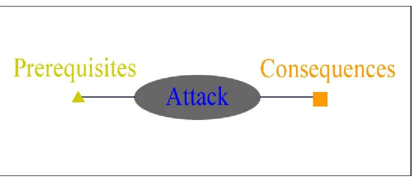
The TIAA system for alert correlation was created at the Cyber Defense Lab of North Carolina State University[17, 19, 31]. The TIAA system uses a system of prerequisites and consequences to group alerts together through a method known as a hyper-alert correlation. The system is based on the idea that many of the attacks described by alerts generated by an Intrusion Detection System can be thought of as having both a set of prerequisites and a set of consequences. An attack combined with its prerequisites and consequences results in what is called a hyper-alert as may be seen in the figure below.
Figure 2.1 Hyper-alert
container. By viewing figure 2 below it is possible to get a better idea of how this might be possible and what such a container might look like.
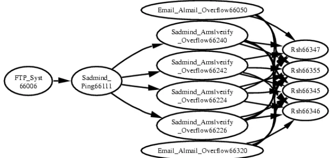
Figure 2.2 Hyper-alert Container
In the figure, a series of hyper-alerts has been taken and coordinated together based on whether their prerequisites and consequences match up properly. A set of alerts is first used to create hyper-alerts. The hyper-alerts are then linked whenever the consequence of one hyper-alert is the same as the prerequisite of another. This matching is represented by the way that all of the ends of the same shape and color are lined up in the figure. What makes this method so exciting is its ability to separate a group of alerts that pertain to one attack from a large set.
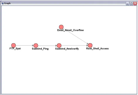
The above figure shows an actual hyper-alert container generated by TIAA from a data set recorded during a Sadmind attack[2]. Sadmind is a Solaris program used to coordinate distributed system operations remotely, and is installed with root privileges in all Solaris machines. The program is vulnerable to buffer overflow attacks which, when successful, allow an attacker to direct a computer to execute any piece of code they supply. Due to the fact that the Sadmind program has root privileges in Solaris machines, this means that attackers can execute any command they wish and have total control of the compromised machine.
The leftmost node of the attack represents the initial FTP access of the system. In the next node, a ping in sent to the system that identifies the presence of the Sadmind vulnerability in the system. In the next vertical row of nodes, the Sadmind vulnerability is being exploited. In the final vertical row of attacks the attacker has achieved root shell access. This means that she can perform any desired task on the compromised machine.
This method of processing alerts, although not perfect, is a good response to problems with current Intrusion Detection Systems. This example shows how the correlation method is able to pull cohesive attacks from a large dataset. A hyper-alert container such as this,
representing an entire attack scenario, is a much more compelling indication that a system has been compromised than a single alert viewed individually could ever be. A sequence of many small anomalies takes on a far greater significance when it is shown to be part of a greater overall sequence. The hyper-alert correlation method has a great potential for making more complicated sequential attacks stand out from a collection of single alerts. This will go a long way to help battle alert overload.
This method also shows promise in catching modified know attacks. One of the commonly used methods of modifying a know attack is to replace one or more aspects of the attack with different methods that will accomplish the same thing. Since this method deals with
Chapter Three
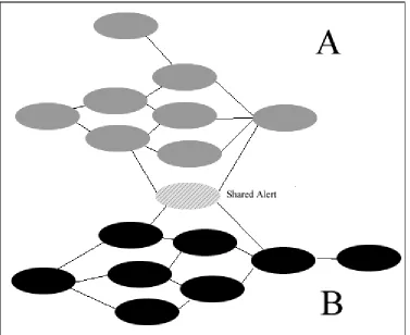
As we set about creating a user interface for the TIAA system and we noticed that the correlation method, although quite powerful, would often generate results that were problematic. Consider the example presented in figure 3.1. Here we see two separate attacks, which the system has erroneously clumped together. The grey nodes on the top of the graph belong to one attack while the black nodes on the bottom of the graph belong to another attack altogether. The problem which arises, is that there is one shared alert which has prerequisites and consequences in both of the attack profiles. This results in the system grouping two separate attacks into one hyper-alert container. There are some very common alerts that will be seen in many attacks, and because TIAA blindly groups everything that matches, this means that all attacks that share this very common alert will be grouped together. This is a very common occurrence and a significant problem.
Recognizing this weakness as well as the fact that some of the hyper-alert containers created by the system were basically nonsensical, it was decided that when the user interface for the hyper-alert container was created it would be useful to allow another round of processing after the hyper-alert container had been created. The blind grouping TIAA relied upon was effective to pull a valid set of alerts pertaining to an attack from a data set. The problem was too many unrelated alerts would be grouped in as well. The system would group different attack collections together when they shared one alert in common as was seen in the last figure. Even in the absence of this problem, the system could generate a strong container such as those seen, then clutter it with alerts that aligned with prerequisites and consequences but weren't really part of the attack.
By allowing a user to further process the hyper-alert containers these problems could be resolved. To see how this is done, let us again consider the hyper-alert container from figure 3.1. Our system enables a security expert to view this graph and perform subset selection on it. This is done by a user clicking on a series of nodes in the graph which they think
represent one cohesive attack. So an expert would take figure 3.1 and break it into two separate attacks by selecting the set of constituent alerts for each of the two attacks present in the container. This same process would allow a user to select out attack from a noisy hyper-alert container.
The research began to look at the possibility of using the TIAA system as a preprocessor for recognizing attacks. Recognizing that it would rarely generate perfect graphs from real datasets did not mean it was useless. Its capability of generating cohesive collections of alerts could serve as a tool for recognizing attacks that would never be seen otherwise. Even if generated hyper-alert containers had a dozen extra alerts, making sense of that was far more manageable that starting from scratch with the thousands of alerts that a system can generate.
to maintain a database of these sets and to use them to try to catch future attempts to use the same attack method. Once this database is in place, it could be used to help see when an attack pattern may be being repeated.
Yet even these carefully selected expert attack profiles would not be perfect. Even if the database had a perfect representation of all attacks (something that is impossible), the very nature of intrusion detection data would mean it would miss many attacks. As has been mentioned earlier, Intrusion detection is an extremely "lossy" data source. At times of high traffic, it is common for alerts to be lost. Often times attacks will occur at times of very high network traffic so this is a serious problem. Consider the following scenario:
Figure 3.2 Missing Alert
This collection of alerts represents a cohesive attack profile. If this attack leads to very heavy network traffic, it is quite possible that one or more of the alerts will be lost. This could make recognizing the attack impossible, no matter how well know it might be.
It is also important to note that this same problem has significant effects on the TIAA hyper-alert correlation system as well. The loss of this one node can lead to this attack being classified in the system as two separate hyper-alert containers. Because the missing alert is acting as bridge between the two main parts of the attack, its absence means that what should be grouped as one hyper-alert container will be grouped as two.
attack data from large datasets. The fact that even this extracted and expertly cleaned data could still be rendered useless in the face of a lossy data source led to further exploration into how hyper-alert containers could be the basis for a more robust tool for recognizing attacks. It was this exploration, which eventually resulted in the creation of the VisualBayes system.
Conversion of Hyper-alert Containers to Bayesian Networks
Figure 3.3 Sadmind Hyper-alert Container
Figure 3.4 Sadmind Hyper-alert Conversion
In the above figure it can be seen how a hyper-alert container may be converted to a
Figure 3.5 Bayesian Sadmind
Chapter Four
Opening the Black Box on Statistical
Modeling, The Theory Behind
As is so often the case in research, we set out to solve one problem and found that what we had created had applications far above and beyond what we had originally intended. We set out to use Bayesian networks to model hyper-alert containers. As we proceeded in this endeavor, we came to realize that the Bayesian tools we were creating would have
applications far beyond simply modeling intrusion data. Our focus gradually went beyond our original task of using belief networks to model one thing. Eventually we saw that what we had created was significant enough to stand on its own and it became known as
VisualBayes.
VisualBayes is a very powerful graphically based tool, which allows the creation,
manipulation, and evaluation of Bayesian networks. It offers features for the representation of Bayesian networks that are not yet seen in other software at the time this thesis is written. The most exciting thing about the software is its ability to marry powerful statistics with easy comprehensibility. We call this marriage opening the black box. A black box is a metaphor that is used to describe systems where the way they accomplish a task is not apparent to the user of the system. Essentially information goes into one end of a black box, and an answer emerges from the other with the user having no idea how that answer was reached.
Before going into the specific details of how we accomplished the task of opening up the black box of our system perhaps it is good to speak to the question of why it was so
important to do so. As humankind's computer systems achieve ever increasing capabilities, they become ever more integrated into everyday life. There is little doubt that almost
just generate correct answers to complicated problems but to do so in ways that are logically comprehensible.
Throughout the history of AI there have been many other systems, which have been designed to simulate intelligent behavior and attempt to generate correct answers to various problems. One of the greatest barriers to the acceptance of these systems has been the black box nature of the way in which they operate. The systems generate answers to questions, but the how and the why of how those answers where reached remains a mystery. In the absence of explanation, users have shown extreme prejudice against accepting the results of expert systems[32]. Acceptance has been far greater when there is more of a collaborative nature to the interaction, with the reasoning of the expert system being both available and
comprehensible to the user[25].
In the VisualBayes system, we tried to create a system that would combine both the robustness of Bayesian Statistical Analysis while at the same time maintaining logical transparency to the user. We accomplished this by using the belief network style where logical connections are connoted by a directed arc and then using these very networks to create a visualization for our users. At the heart of our motivation in creating this software are three important technologies from Computer Science. These technologies are
Information Hiding, Bayesian Statistical Modeling and Information Visualization and they will each be considered in turn.
4.1 Information Hiding
far more comprehensible when information hiding is practiced[3]. Information hiding is the foundation of the object oriented programming that we see today, but it is important to note that the concept of information hiding carries with it an additional meaning beyond simply the encapsulation and modularization seen in object oriented programming. Information hiding does not just mean that we break up a program into separate subunits, it means that we break a program into separate subunits and we base the composition of those subunits around the decisions that the program making[13, 21]. Effective information hiding means that we have logically composed subunits of our software that are completely capable of making certain decisions or evaluations themselves.
One of ways that information hiding may be best understood as looking at it as making possible a higher level of abstraction which may be put in place on top of computer code. To better comprehend this, consider one of the best know uses of a higher level of abstraction in Computer Science, the use of high level languages. The original computer programs were written entirely in machine language. Machine language consists of the basic commands that tell a processor what to do with high and low electric potentials. This is the nitty-gritty of what a computer is doing when it runs any computer program. Early Computer Scientist found that programmers could comprehend and produce much more complicated programs when they made use of high-level languages such as C and Fourtran. High-level languages allow programmers to leave behind machine code and work using far more comprehensible language constructs. A compiler will come along and eventually convert everything written into machine code , but because the program is conceived at a higher level of abstraction, the programmer can both conceive of far more complicated constructs and write computer
Figure 4.1 Levels of Abstraction
There are many benefits which arise from having multiple levels of abstraction within computer software. The structure and grouping of software modules give a structure to a computer program that make it far more comprehensible. A programmer does not have to understand every line of code, they can look at the structure and interaction of modules and readily see how a program is accomplishing tasks and what parts of the program are
accomplishing certain tasks. This makes it far easier for programmers to understand the overall structure of the code. Also if an error occurs in one of the tasks that the program is performing, it is far easier to identify the code that may be responsible for the error.
Conclusions on Information Hiding
proper modeling. It is this kind of effective compartmentalization of various aspects of tasks into modules that will result in the visualization we create being readily comprehensible.
4.2 Bayesian Statistical Modeling
Once we have broken the various portions of a problem into separate subunits through the use of Information Hiding, there remains the problem of how to show the various relations and interactions of these various subunits. One of the methods which has been applied towards this task is Bayesian Statistical modeling. Bayesian networks are an excellent way to model complicated real world situations were we have large collections of separate events that may or may not influence each other. Bayesian Networks have been used previously to recognize malicious activity in telecommunications networks[24] and also to try to perform malicious event classification in a UNIX environment[11]. We had seen that it was easy to make plausible Bayesian networks from the hyper-alert containers that TIAA was generating, so we set out to create a system that would be capable of working with these networks.
The foundation of the underlying technology for Bayesian networks can be traced all the way to British mathematician Thomas Bayes who lived from 1702 – 1761. During his life Bayes wrote a paper entitled ``Essay Towards Solving a Problem in the Doctrine of Chances,'' that he never published. It was only a few years after his death that a friend noticed this paper and had it published[14]. The paper contained a very simple equation that has subsequently come to be known as Bayes' Law.
Figure 4.2 Bayes' Law
Norvig (known by many as The Bible of Artificial Intelligence) has stated that "This simple equation underlies all modern AI systems for probabilistic inference."[23] To better understand it we will look at an example taken from that same text.
We know from research that the disease meningitis causes a patient to have a stiff neck 50% of the time. This means that the probability of a stiff neck given that a patient has meningitis P(S|M) = .5. We also know that the probability that a person has meningitis P(M) = 1/50,000 and the probability that a person has a stiff neck P(S) = 1/20. Bayes' law allows us to use all of these known probabilities to calculate one we don't know i.e. given all the above
information, what is the probability that someone with a stiff neck has meningitis P(M|S)? The calculation using Bayes' law is straightforward:
Figure 4.3 Bayes Calculation
It is possible to perform statistical calculations when more than just two values are under consideration. The calculations get exponentially more complicated yet they are still calculable. To represent the interactions between the probabilities of multiple variables a data structure has been developed known as Bayesian Networks. Russell and Norvig[23] describe Bayesian networks as directed arc graphs where each node is annotated with quantitative probability information and the following specifications are true:
1. A set of random variable make up the nodes of the network. Variable may be discrete or continuous.
2. A set of directed links or arrows connects pairs of nodes. If there is an arrow from node X to Node Y, X is said to be the parent of Y.
3. Each node Xi has a conditional probability distribution P(Xi|Parents(Xi)) that quantifies the effect of the parents on the node.
In simpler terms, what all this means is that these graphs are ways to represent the way that various probabilities interact with each other. Again this is better illustrated through an example than an explanation.
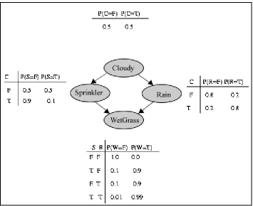
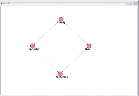
Consider the following scenario. We have a small patch of grass on a Seattle lawn. This patch of grass has a sprinkler system. The sprinkler system has little need to operate because it often rains and when it does the sky is usually cloudy. There is also a squirrel that spends about half her time on the lawn whether it is wet or not. This situation may be represented by the following set of nodes:
Figure 4.4 WetGrass Nodes
To make this set of nodes into a Bayesian Network we draw directed arcs between nodes where the value of one influences the probability of another giving us the following:
Figure 4.5 WetGrass Nodes with Connections
In this figure we see that both Sprinkler and Rain are connected to WetGrass. This is because both the sprinkler and the rain can make the grass wet. We also see Cloudy
nothing, because she has no effect on the probability of the other nodes and they have no effect on her. This complete set of nodes make a Bayesian Network. Here is a list of probabilities for this scenario[15, 23].
Figure 4.6 WetGrass Nodes with Probabilities
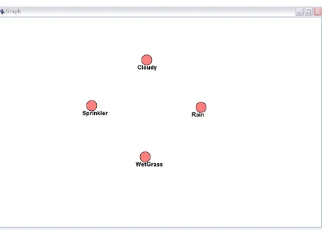
Figure 4.7 Graph Canvas
Figure 4.8 Graph Canvas with Nodes
Figure 4.9 Graph Canvas with Labeled Nodes
Figure 4.10 Graph Canvas with Connected Nodes
Figure 4.11 Edit Variable Dialogue
Figure 4.12 Edit Function
This action brings up the dialogue to the left and allows the probability values from the tables to be entered. These probabilities could come from mining a data set or from expert knowledge, for the purposes of this demonstration, we are simply using the table above. This process is repeated until we have the complete set of probabilities in the system.
4.3) Visualization
of the generated information be presented. Throughout the past, there have been many expert systems in AI which analyzed data sets and generated decisions based on the information contained within those data sets. It has been often found that even when expert systems generate consistently correct data, if a user cannot understand how that decision was reached they will be reticent to accept it[32].
After the addition of probabilistic modeling to networks, it became clear that the system had become so complicated that a more comprehensible way was needed to present results. It would be possible to simply tell the user that the system thought there was an attack. User acceptance of system classifications would be far higher if the reasons for decisions where clearly shown. The problem of presenting this data was a difficult one. It would have certainly been possible to perform a raw data dump to the user. Since this data would be what had lead to the system reaching a certain classification giving it to a user would be the reason a certain decision had been reached. Many of the probabilistic tools in use today output their results in text format, which can be very difficult to comprehend. In a simple system this might be sufficient, but our system had quickly become so complicated that a list of data or even a processed list of alert and probabilities would be so large as to be
incomprehensible.
4.3 Data Visualization
One of the best methods for presenting large data sets it through the use of visualizations[9]. An indecipherable spreadsheet can often become clear and easily understood when the data is put in the form of a graph. A visualization of a data set allows for outliers and patterns to be readily identified[10, 22]. It was obvious the use of a visualization would be a good solution for our application, but it was necessary to determine what form that visualization should take.
The Bayesian networks that were used to make the decisions were used as the basis for our visualization. The arc structure of the networks themselves represented the logical
the Bayesian networks by color-coding the nodes based on their probabilities. The nodes were tinted with red based on their probability as seen in fig 4.13 This color-coding allows a user to glance at an image and see the probability distribution of the entire network. By using a color representation of the probability of each node in the network we are able to immediately determine the basic probability of any of the nodes.
Figure 4.13 Color Gradient
Once we were visually representing the probabilities of the nodes within the graph it was immediately possible to identify areas of high and low probability within the network. This made it quite simple to make immediate assessments of the probability of various nodes within the network, and it was also possible to see the areas of the network that were
effecting that probability. We were able to see from the general color trends the distribution of probabilities that was leading to a measured probability. This was a very valuable
augmentation, but a critical bit of information was still lacking from the visualization we had created.
By viewing our color-coded networks, it was a simple matter for us to determine a
and immediately determine the constellation of observations that had lead to that particular probability distribution.
There are also interesting emergent properties within the system when we switched the nodes to graphical representations of their probabilities. It becomes possible to see trends in the probabilities of the network. It became possible to view the effects of events as they influenced the probabilities throughout the network. It became possible to see trends throughout the networks, as new data changed probability distributions. It even became possible to sometimes see the most probable cause of an observation by noting the most intensely colored path through the network.
To better illustrate how these visualizations were executed we will consider a simple example. Here we have a basic Bayesian network that should be familiar at this point. The probability distribution for the this example can be seen in fig. 4.6 The basic network with no visualization may be seen in the following figure:
Figure 4.14 WetGrass with no Visualization
Figure 4.15 Grass Wet and Dry Visualization
The likelihood that a node is true is represented by the degree of redness of the node. The more red the node the greater the probability that it is true. In the figure above, we can see the effects of observing if the grass is wet or dry. If is observed to be dry we see the
probability of rain and the sprinkler decrease. If it is observed wet, those same nodes exhibit an increase in probability. If we take the network on the right side with the wet grass and observe the clouds, the following two graphs are obtained:
Figure 4.16 Visualizations with Clouds
shows that if clouds are present, then rain is the likely cause of the wetness. This is certainly a very trivial example, but the way it illustrates the effectiveness of the visualization is not trivial at all.
This use of the Bayesian Networks themselves to create visualizations is clearly the most exciting development to come out of this research. Kevin Murphy maintains a list of graphical Bayesian Network software online[16]. The list contains 41 software systems. A review of all of these systems shows that none of these systems seem to be creating
Chapter Five
The first step in the creation of the VisualBayes system was the creation of an overall operating environment for the system. We started with a desktop pane that was to contain and launch all elements of the software package.
Figure 5.1 Desktop Pane
Figure 5.2 Graph Canvas
Figure 5.3 Variable Probability
The next addition to the software was the Graph Properties frame, this allowed users to view and change the method used to form some of the probability calculations.
Figure 5.4 Graph Properties
Figure 5.5 Data Objects Pane
The second tab linked to the Connections pane and could be used to see all other nodes which were connected to a certain node.
Figure 5.6 Connections Pane
You can see that we have various probabilities displayed by sliders. When we click on various nodes in the network their various probabilities will be shown. The currently
This example comes from a very simple network designed to model whether or not an office cabinet needs to be resupplied. As things stand in this figure there is a fifty fifty chance that it is true that the cabinet needs to be resupplied. The user has also set the alarm to sound an alert if the probability that the cabinet needs resuppliying is true meets or exceeds 80 percent.
Final Product
All of these various elements are combined to make up our final software product seen below.
Figure 5.9 Complete VisualBayes Software
Chapter 6
Once the VisualBayes system had been created and was in a functional form, the next step was user testing. In the user testing there were three main hypotheses that would be tested.
1)
The VisualBayes software package would allow nonexpert users to make use of Bayesian statistics2)
The VisualBayes software would be intuitive and easy to learn3)
The visualization of probabilities by the software would be readily understood by usersTo test these three hypothesis, a series of experiments were conducted
Experimental setup
The experiment was conducted on a random sampling of ten undergraduate students who volunteered to participate. Undergraduate students in fields other than Computer Science were chosen to help ensure that the students would lack expertise in Bayesian Networks. Participants were compensated five dollars to participate in the research.
Stage One Tutorial
The first stage of the experiment consisted of a brief introduction to the VisualBayes system. Participants were walked through a simple example. They were shown a Bayesian network that modeled a simple scenario. In the tutorial, subjects were shown how observations were made. How to query the resulting network nodes for probabilities was demonstrated. The relation between the probability that a node was true and it’s degree of redness was explained to the subjects.
Stage Two, Wet Grass Network
Figure 6.1 WetGrass Network
The subjects were then asked to query the network to determine the probability that grass wet is true, in the absence of any observations. The subjects where then asked to enter in an observation that it was cloudy into the network. They were then asked to again query the network and to determine the probability that the grass was wet given the observation that it was cloudy. They were then asked to add a second observation that the grass was wet. They were then asked to switch the observation between cloudy and not cloudy until they could notice a difference between the two networks based on whether or not it was cloudy, or they determined that they could not see a difference. The subjects where then asked to set cloudy to true and grass wet to true and to answer whether they thought that rain or the sprinkler was the more likely cause of the wet grass based on the network visualization. The subjects were then asked to switch the cloudy observation to false and to again answer the question of whether they thought that rain or the sprinkler was the more likely cause of the wet grass based on the network visualization.
Stage Three Fire Alarm Visualization
In the final stage of the testing we assessed the subjects ability to make use of a the
house contains one or two fire sensors. In the baseline testing the subjects were given the following image. Master Bedroom Bathroom 2nd Bedroom Alarm Alarm Alarm Alarm Alarm Alarm Living Room Kitchen Dining Room Alarm Alarm Alarm Alarm Alarm Alarm Upstairs Furnace Laundry Main Floor Basement Alarm Alarm
Figure 6.2 Lookup Table of Alarm Locations
This image in figure 6.2 is a representation of the house alarm system. The table shows each alarm label and its location. The house has a main floor and an upstairs as well as a
After the subjects had performed the three alarm identifications with the lookup chart, they were given the following VisualBayes representation of the alarm network.:
Figure 6.3 VisualBayes Representation of Alarm Network
Figure 6.4 Alarm k Visualization
The subjects were shown that the observation of Alarm k was represented in the visualization by it being circled in blue. They were shown how this observation changed the probabilities for Dining Room, Main Floor, and Fire Alert. They were also told that this increase in probabilities was represented by the fact that these nodes were now shaded with red.
Figure 6.5 Alarm j, k, and m
For the final test the subjects were given the following alarm network and asked to identify what observations had caused the alarm to sound:
This concluded the testing portion of the examination. The subjects where then asked to rank how straightforward they found working with the visualizations on a scale from one to five.
Results of the testing
Ten subjects were tested, all where undergraduates and none were computer science students.
The overall results of the testing were extremely encouraging. After a brief tutorial, all the test subjects were able to use the system well. In the wet grass example, all the subjects were able to us the VisualBayes software to correctly calculate probabilities. The following results were obtained:
Table 6.1 Task Completion for WetGrass Network
Task # Correct answers /
# Subjects
%Correct
Correctly identify probability grass is wet in absence of observations
10/10 100
Enter observation that it is cloudy 10/10 100
Correctly query network for new probability that grass is wet with observation of cloudiness
10/10 100
Enter observation that it is cloudy 10/10 100
Switch between observation of cloudy and not cloudy and identify whether the sprinkler or rain is more likely cause of wet grass in each situation
10/10 100
Table 6.2 Times for Alarm Identification with Lookup Table
Task Average time
Identify room and floor for alarm g 12.36 seconds
Identify room and floor for alarm b 9.78 seconds
Identify room and floor for alarm m 11.85 seconds
Total Time 33.99 seconds The following average times were obtained when using the VisualBayes network
visualizations of the alarm network
Table 6.3 Times for Alarm Identification with Visualization
Task Average time
Identify room and floor for alarm j 3.88 seconds
Identify room and floor for alarm c 2.95 seconds
Identify room and floor for alarm n 2.82 seconds
Total Time 9.64 seconds
Looking at these times, it may be concluded that the subjects were able to use the
VisualBayes alarm network visualization, and that their performance was significantly better with its use. The times to obtain nearly identical information was significantly faster when the visualization was used.
1 2
3 4
5 6
7 8
9 10 Time for three visualization tasks Time for three lookup tasks 0 10 20 30 40 50 60 70 80 Time Subject Number
Total time of three lookup tasks paired with total time of three visualization tasks for each subject
Time for three visualization tasks Time for three lookup tasks
Figure 6.7 Graph of Time to Recognize Information
In the graph, the front row (in blue) is the total time for three visualization-based tasks. The back row (in purple) is the time for three lookup-based tasks. It is clearly seen that each subject's performance was significantly improved with the use of the visualization.
Table 6.4 Task Completion for Alarm Identification
Task # Correct answers /
# Subjects
%Correct
Correctly identify that Alarm a and Alarm b had triggered an alarm
10/10 100
Upon completion of the testing, the subjects were asked to rank their subjective experience of using the visualizations.
Table 6.5 Self Assessed Satisfaction
Question Average answer
On a scale from one to five, how straightforward did you find working with the network visualizations created by VisualBayes?
Chapter Seven
Conclusions
and
7.1 Directions for Future Research
The primary direction we envision for future research from this work lies in further testing of the VisualBayes system. In our preliminary testing we have established that the VisualBayes system can effectively present Bayesian networks to users with little understanding of the networks themselves. We would like to go on to use the system to visualize a wider range of problem domains and measure how comprehensible the resulting visualizations are to users. It would also be useful to test the speed and effectiveness of the VisualBayes system as it compares to other methods of presenting similar data.
Another interesting addition to the VisualBayes system as a security tool would be to augment the networks created from hyper-alert containers with additional data sources. Rather than only searching through alert data the system would allow users to add additional nodes that would represent other data sources.
Figure 7.1 Data Node
Data nodes
Types of Data Nodes
Basic information
These types of nodes may be easily made to cover a wade range of different data types. They may consist of data such as what day of the week it is. Whether a username is a in a system administrator list. Whether a certain activity is occurring during normal business hours.
System Data
System data nodes would allow the inclusion of data relevant to various aspects of the system on which it is running. Certain parameters such as memory usage or network traffic may be utilized to model certain attack hypotheses.
Past Usage
It will be possible to make use of previous data sets to examine data. Certain items can be identified as anomalous if they differ significantly form past usage. There has also been interesting work performed in data mining past data sets to recognize attacks[12].
External Data
An interesting idea is to make use of external data sources. The fact that current attacks can spread worldwide in less than a day means that preexisting system configurations may be insufficient to catch the latest attacks. It would be possible to query the Internet and gather additional data to assist in the classification of an attack.
7.2 Advantages of the VisualBayes System
Plasticity of Response
ability to recognize future variations of know attacks. Intruders will often slightly modify preexisting attacks or some alerts will be lost due to high network traffic. An overly specific pattern matcher will miss this modified attack while a Bayesian based system will stand a far better chance of catching it.
It is also important to note that these data sets can sometimes be quite noisy. It is not uncommon for alerts that should be caught to slip through the system due to high traffic or other reasons[19]. It is also important to note that because networks can be distributed systems, all portions of an attack will not necessarily occur at the same site. This means that one portion of an attack occurs at one location of a system, while another portion occurs at a different location. Because a Bayesian network can trigger an alert while only seeing a fractional portion of an attack, our implementation offers significant advantages for recognizing both partial and modified attacks.
Compactness of Storage
There is a significant decrease in the volume of data which must be stored once the system is switched over to a Bayesian format. A problem, often referred to as the “time window” constraint, is well documented in IDS’s. This problem is that given a finite amount of storage and a data stream constantly producing a large amounts of new data, given sufficient time, eventually the stored data will exceed the storage space. When this happens the system must either make use of auxiliary storage or begin to overwrite data.
The fact that our system is triggering alerts based solely on the satisfaction of our Bayesian networks means that we do not suffer from this time window problem. We only need to permanently store data for those items which will affect the networks. The data, which has no effect on any of the system’s networks, can then be discarded. Although this system will not be able to retroactively gather data once a new network has been created, this is still an enormous improvement over past systems. Once a network has been placed within the system it can watch for that attack for an indefinite time period. Because the system only needs to store values that affect networks and not the entire data stream, the time window problem has been overcome.
This will also have a marked benefit in security for distributed systems. In distributed systems, there is a need for security information to be shared between a range of computers. If one of the computers is evaluating a particular attack scenario, it will not need to see the entire data set from another machine, rather it will only need to query and view data relevant to the network that is being considered. This leads to a huge reduction in the information that must be shared between machines and enormously simplifies monitoring of a distributed system.
7.3 Conclusions
The work done in the evaluation of Intrusion Detection Systems appears to have established the difficulty of the problem more than identified a clear solution. The TIAA system remains a very good idea with serious challenges to effective implementation. Since this research was done the TIAA system has evolve further and addressed some of the issues presented in this thesis.
Chapter Eight
1. Baskerville, R. Information systems security design methods: implications for information systems development ACM Comput. Surv. , 25 (4 ). 375-414 2. ComputerEmergencyResponseTeam. CERT® Advisory CA-1999-16 Buffer
Overflow in Sun Solstice AdminSuite Daemon sadmind
http://www.cert.org/advisories/CA-1999-16.html, 1999.
3. Coulter, N.S. Information hiding, the Intel iAPX 432,and Ada in Proceedings of the
20th annual Southeast regional conference ACM Press, Knoxville, Tennessee 1982
160-167
4. Cozman, F.G. The JavaBayes system. The ISBA Bulletin, Vol. 7 (No. 4). 16-21. 5. Dain, O. and Cunningham, R., Fusing a heterogeneous alert stream into scenarios. in
2001 ACM Workshop on Data Mining for Security Applications., (2001), 1-13.
6. Dechter, R., Bucket elimination: a unifying framework for probabilistic inference. in
Twelfth Annual Conference on Uncertainty in Artificial Intelligence, (1996).
7. Dreger, H., Feldmann, A., Paxson, V. and Sommer, R. Operational experiences with high-volume network intrusion detection in Proceedings of the 11th ACM conference
on Computer and communications security ACM Press, Washington DC, USA 2004
2-11
8. Fan, W., Miller, M., Stolfo, S.J., Lee, W. and Chan, P.K., Using artificial anomalies to detect unknown and known network intrusions. in Data Mining, 2001. ICDM 2001,
Proceedings IEEE International Conference on, (2001), 123-130.
9. Gershon, N. and Eick, S.G. Visualization's new tack: making sense of information.
Spectrum, IEEE, 32 (11). 38-40, 42, 44-37, 55-36.
10. Kincaid, R. VistaClara: an interactive visualization for exploratory analysis of DNA microarrays in Proceedings of the 2004 ACM symposium on Applied computing ACM Press, Nicosia, Cyprus 2004 167-174
11. Kruegel, C., Bayesian Event Classification for Intrusion Detection. in 19th Annual
Computer Security Application Conference (ACSAC), (2003).
12. Lee, W. and J.Stolfo, S., Data Mining Approaches for Intrusion Detection. in 7th
USENIX Security Symposium, (1998).
13. Leino, K.R.M. and Nelson, G. Data abstraction and information hiding ACM Trans.
14. Leonhardt, D. Adding Art to the Rigor of Statistical Science The New York Times, New York, 2001.
15. Murphy, K. A Brief Introduction to Graphical Models and Bayesian Networks,
http://www.cs.ubc.ca/~murphyk/Bayes/bnintro.html, 1998.
16. Murphy, K. Software Packages for Graphical Models / Bayesian Networks,
http://www.cs.ubc.ca/~murphyk/Software/BNT/bnsoft.html.
17. Ning, P., Cui, Y., Reeves, D. and Xu, D. Tools and Techniques for Analyzing Intrusion Alerts. ACM Transactions on Information and System Security, 7 (2). 273-318.
18. Ning, P., Jajodia, S. and Wang, X.S. Intrusion Detection in Distributed Systems: An
Abstraction-Based Approach. ADVANCES IN INFORMATION SECURITY:, 2004.
19. Ning, P., Xu, D., Healey, C.G. and StAmant, R.A., Building Attack Scenarios through Integration of Complementary Alert Correlation Methods. in 11th Annual
Network and Distributed System Security Symposium (NDSS '04), (2004), 97-111.
20. Ning, P., Y.Cui and Reeves, D.S., Constructing attack scenarios through correlation of intrusion alerts. in 9th ACM Conference on Computer and Communications
Security, (2002), 245-254.
21. Parnas, D.L. On the criteria to be used in decomposing systems into modules
Commun. ACM 15 (12 ). 1053-1058
22. Qian, Y. and Zhang, K. The role of visualization in effective data cleaning in
Proceedings of the 2005 ACM symposium on Applied computing ACM Press, Santa
Fe, New Mexico 2005 1239-1243
23. Russell, S.J. and Norvig, P. Artificial intelligence: a modern approach. Prentice-Hall, Inc., Upper Saddle River, NJ, 2003.
24. Sebyala, A.A., Olukemi, T. and Sacks, L. Active Platform Security through Intrusion Detection Using Naïve Bayesian Network for Anomaly Detection.
25. Shepherd, A. and Ortolano, L. Water-Supply System Operations: Critiquing Expert-System Approach. Journal of Water Resources Planning and Management, Vol. 122
26. Sommers, J., Yegneswaran, V. and Barford, P. A framework for malicious workload generation in Proceedings of the 4th ACM SIGCOMM conference on Internet
measurement ACM Press, Taormina, Sicily, Italy 2004 82-87
27. Spitzner, L. The Honeynet Project: trapping the hackers. Security & Privacy
Magazine, IEEE, 1 (2). 15-23.
28. Thompson, C. The Virus Underground The New York Times Magazine, 2003, 28-33. 29. Valdes, A. and Skinner, K., Probabilistic Alert Correlation. in International
Symposium on Recent Advances in Intrusion Detection( RAID 2001), (2001), 54-68.
30. Vigna, G., Robertson, W. and Balzarotti, D. Testing network-based intrusion detection signatures using mutant exploits in Proceedings of the 11th ACM
conference on Computer and communications security ACM Press, Washington DC,
USA 2004 21-30
31. Xu, D. and Ning, P., Alert Correlation through Triggering Events and Common Resources. in 20th Annual Computer Security Applications Conference, (2004). 32. Ye, L.R. and Johnson, P.E. The Impact of Explanation Facilities on User Acceptance