18th International Conference on Structural Mechanics in Reactor Technology (SMiRT 18) Beijing, China, August 7-12, 2005 SMiRT18-B02-3
ASSESSMENT OF THE DETAILED LINEAR-ELASTIC STRESS
CALCULATION OF 90°-BENDS BASED ON THE ELASTIC-PLASTIC
METHOD
Wieland Holzer*
TÜV Industrie Service GmbH
TÜV SÜD Group
Westendstrasse 199
80686 Munich Germany
Phone: +49 89 5791-2773,
Fax: +49 89 5791-2837
E-mail: [email protected]
Christian Huettner
TÜV Industrie Service GmbH
TÜV SÜD Group
Westendstrasse 199
80686 Munich Germany
Phone: +49 89 5791-1274,
Fax: +49 89 5791-2837
E-mail: [email protected]
ABSTRACT
Normally, for the stress calculation of piping systems the transverse beam theory is used. To evaluate the stresses at the bends we also have to use the stress concentration factors B and C given in the literature. When the stresses calculated with the stress concentration factors B and C exceed the permitted primary or secondary stresses, we have to do a detailed 3D finite element analysis for the bends. But often it’s very difficult to evaluate the finite element results, because mostly the permitted stresses given in the design codes are only limited for the cross section.
In our experience it’s very common to use the method given in the KTA 3201.2 [1] (tab. 8.4-4) and KTA 3211.2 [2] (tab. 8.5-4) for the evaluation of the detailed stress analyses of bends. But this method is not easy to use, because now we have to separate the stresses into primary membrane stresses Pm and Pl and primary and secondary bending stresses Pb and Q for the load types internal pressure and bending moment.
Often this method given in the KTA 3201.2 [1] (tab. 8.4-4) and KTA 3211.2 [2] (tab. 8.5-4) is not successful, because 75% of the bending stress (over the wall-thickness) caused by the load type bending moment has to be compared with the stress permitted for the primary bending stress Pb. This is widely considered to be overly conservative.
So in this paper for normal operating conditions we developed a basis to decide if a detailed elastic-plastic analysis for a bend would be useful or not, if the linear elastic method fails or the stresses calculated by the transverse beam theory using the stress concentration factor B2 exceed the permitted stresses. For this task we use the elastic-plastic finite element method to determine the corresponding collapse load.
Our results show, that for the load type bending moment often it’s worth to evaluate the situation with a detailed limit analysis, especially for small values of the characteristic bend parameter h. But our results also show, that it’s important to evaluate the interaction of the bending moments and internal pressure very carefully when using the limit analysis method.
1 INTRODUCTION
Normally, for the stress calculation of piping systems the transverse beam theory is used. To evaluate the stresses at the bends we also have to use the stress concentration factors B and C given in the literature. In this paper we focus on the factor B2, as shown in equations (1) and (2). In our experience, the factor B2 is the most important uncertainty factor for analyzing the stress condition of bends.
σ = B1 x (da x p)/(2s) + B2 x (da x M)/(2 I) ≤1,5Sm (1)
B2 = 1,3/h2/3 (2)
Often the stresses calculated by equations (1) and (2) exceed the permitted primary stress 1,5Sm. In this case it’s very common to use a detailed 3D finite element analysis to analyze the stress conditions. The difficulty is, to evaluate the finite element results, because mostly the permitted stresses given in the design codes are only for the cross section.
In our experience it’s very common to use the method given in the KTA 3201.2 [1] (tab. 8.4-4) and KTA 3211.2 [2] (tab. 8.5-4) for the evaluation of the detailed stress analyses of bends. But this method is not easy to use, because now we have to separate the stresses into primary membrane stresses Pm and Pl and primary and secondary bending stresses Pb and Q for the load types internal pressure and bending moment.
So we have to developed a basis to decide if a detailed elastic-plastic analysis for a bend would be useful or not, if the linear elastic method fails or the stresses calculated by the transverse beam theory using the stress concentration factors B2 and C2 exceed the permitted stresses. For this task we use the elastic-plastic finite element method to determine the corresponding collapse load. For the calculations of this paper we used the FE-code ANSYS 9.0 [3]. The method presented in this paper is focused to the normal operating conditions.
2 LINEAR-ELASTIC FINITE ELEMENT ANALYSIS
If we use a detailed 3D finite element model to analyze the stress conditions it’s necessary to separate the stresses into primary stresses Pm an Pl and primary and secondary bending stresses Pb and Q as shown in table 1.
Load Stress
(relating to the wall thickness) Stress category
Internal pressure Membrane stress Bending stress
Pm Q
External loads (bending moment)
Membrane and torsional stress Bending stress (75%) Bending stress (25%)
Pl Pb Q
Thermal expansion (bending moment)
Membrane and torsional stress
Bending stress Q
Table 1: Stress categories for the detailed stress analysis of bends given in the KTA 3201.2
[1] (tab. 8.4-4) and KTA 3211.2 [2] (tab. 8.5-4)
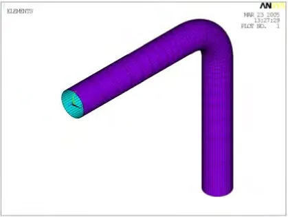
Figure 1: Finite element model of the bend using shell elements
The calculation of one load step also only needs a few minutes on a personal computer. But first to separate the loads for every bend into bending moments resulting form external loads (weight, earthquake, pressure surge…) and thermal extension of the piping system often is very time-consuming for a real piping calculation considering every service condition. To make clear the expenditure of evaluating the stresses caused by bending moment and internal pressure we used a parametric finite element model as shown in figure 1:
- First the membrane and bending stresses caused by the internal pressure had to be calculated. For this the maximum stresses of the top, middle or bottom layer of the shell-elements have to be analyzed. The middle layer stress has to be compared with the maximum permissible Pm. The top layer stress is defined as Q.
- The second step is to calculate and analyze the stresses caused by bending moments separately for external loads and thermal expansion. For this 75% of the maximum top layer stress caused by external loads is defined as Pb and 25% of the maximum top layer stress is defined as Q. The maximum top layer stress caused by the thermal moment also is defined as Q.
- The next step is to check if the obtained results are permissible or not as shown in equation (3).
Pm (internal pressure) ≤ Sm (3a)
Pm (internal pressure) + Pl (external loads, bending moment, 75%) ≤ 1,5Sm (3b)
Pm (internal pressure) + Pl (external loads, bending moment, 75%)
stresses caused by the different load types and not the maximum sums of stresses for every node of the finite element model. The second reason is that the equation (3b) seems to be overly conservative. So it’s necessary to determine the relevant node considering the correct maximum stresses.
Because this process is difficult and time-consuming we developed a method to check if it’s worth to evaluate the stress condition by a limit analysis.
3 ELASTIC-PLASTIC FINITE ELEMENT ANALYSIS
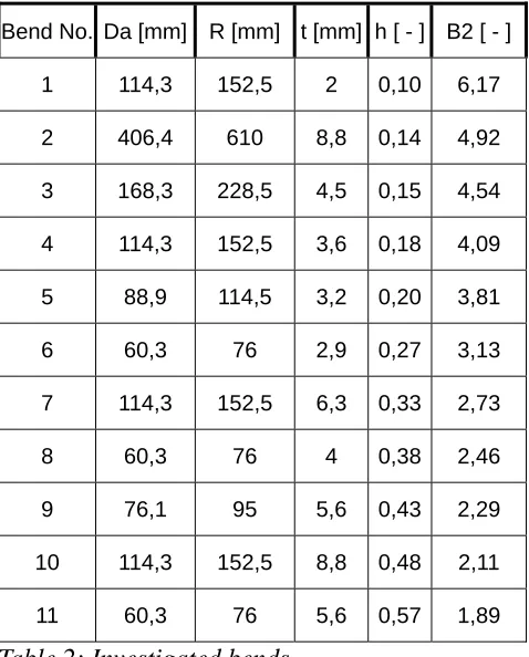
For the bend parameters shown in table 2 we investigated if it’s worth to evaluate the stress conditions with a limit analysis or not.
Bend No. Da [mm] R [mm] t [mm] h [ - ] B2 [ - ]
1 114,3 152,5 2 0,10 6,17
2 406,4 610 8,8 0,14 4,92
3 168,3 228,5 4,5 0,15 4,54
4 114,3 152,5 3,6 0,18 4,09
5 88,9 114,5 3,2 0,20 3,81
6 60,3 76 2,9 0,27 3,13
7 114,3 152,5 6,3 0,33 2,73
8 60,3 76 4 0,38 2,46
9 76,1 95 5,6 0,43 2,29
10 114,3 152,5 8,8 0,48 2,11
11 60,3 76 5,6 0,57 1,89
Table 2: Investigated bends
3.1 Bending Moment
The first step is to determine the bending stress caused by the load type in-plane bending moment with the linear-elastic finite element model. For this calculation we used shell elements. The second step is to define the fictitious yield stress as shown in equation (4) for the limit load analysis.
σYS = 1.5 x 75% x Pmin-plane bending (4)
Figure 2: Finite element model of the bend using solid elements
The permissible bending moment according to KTA3201.2 is 2/3 of the plastic collapse moment obtained with the elastic-plastic finite element analysis. For the decision if it’s worth or not to carry out an elastic-plastic limit load analysis we defined the ratio FMb plastic/elastic of the permissible elastic plastic bending moments and the permissible linear-elastic bending moments as shown in equation (5). If the ratio is >1 it’s worth to carry out an elastic plastic limit load analysis.
FMb plastic/elastic ={(2/3) x Mb, collapse}/Mb, elast 75%Pl (5)
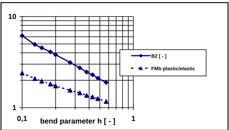
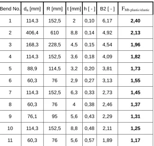
The results for the investigated geometric parameters are shown in figure 3and listed in table 3.
1
10
0,1
bend parameter h [ - ]
1
B2 [ - ]
Bend No. da [mm] R [mm] t [mm] h [ - ] B2 [ - ] FMb plastic/elastic
1 114,3 152,5 2 0,10 6,17 2,40
2 406,4 610 8,8 0,14 4,92 2,13
3 168,3 228,5 4,5 0,15 4,54 1,96
4 114,3 152,5 3,6 0,18 4,09 1,82
5 88,9 114,5 3,2 0,20 3,81 1,73
6 60,3 76 2,9 0,27 3,13 1,55
7 114,3 152,5 6,3 0,33 2,73 1,45
8 60,3 76 4 0,38 2,46 1,37
9 76,1 95 5,6 0,43 2,29 1,31
10 114,3 152,5 8,8 0,48 2,11 1,25
11 60,3 76 5,6 0,57 1,89 1,17
Table 3: F
Mb plastic/elasticfor investigated characteristic bend parameters
The results in table 3 and figure 3 show, that for the load type bending moment it’s worth to evaluate the situation with a detailed limit analysis, especially for small values of the characteristic bend parameter h. If the stresses calculated by equation (1) exceed the permitted primary stress, in a first step the factor B2/FMb plastic/elastic can be used for a rough quantitative estimation of the possible limit loads. But here we emphasize, that it’s always necessary to carry out a detailed analysis if the linear-elastic analysis or the calculation by using the equations (1) and (2) fails.
3.2 Internal Pressure
The next step of our investigation is to analyze the influence of the load type internal pressure. For this we first determined the membrane stress Pm caused by the load type internal pressure with the linear-elastic finite element model shown in figure 1. Then the fictitious yield stress was determined by the obtained stress value as shown in equation (6) for the limit load analysis.
σYS = 1.5 x Pminternal pressure (6)
The results of the elastic-plastic analysis show, that the obtained limit load is only slightly higher than the linear-elastic result (max. 4%), if the equivalent stress (distortion-energy theory) is used for the linear-elastic calculation. Furthermore the linear-elastic FEM results show, that there is no real difference to the results obtained by the analytical dimensioning as specified in the design codes, if the maximum shear stress theory (ANSYS stress intensity) is used for the linear-elastic FEM.
The facts described above are well-known for the straight pipe. For the cross sections da/di ≤ 1.2 there is also no important difference between the results obtained by a limit load analysis, a linear-elastic FEM-analysis and the analytical analysis, if the equivalent stress is used. For straight pipes the limit load can be determined by equation (7) given in [4].
So finally for the load type internal pressure the limit values for the membrane stress given in table 1 can not be consider as being overly conservative.
3.3 Considering Bending Moment and Internal Pressure
To analyze the stress conditions completely, the load types bending moment and internal pressure must be considered simultaneously. Therefore the correct bending moment obtained by the piping calculation and the correct or conservative boundary conditions must be considered. Then a correct limit load analysis is possible, without separating into thermal bending moments and bending moments caused by external loads.
4 SUMMARY AND CONCLUSION
Often the method given in the KTA 3201.2 [1] (tab. 8.4-4) and KTA 3211.2 [2] (tab. 8.5-4) is not successful, because 75% of the bending stress (over the wall-thickness) caused by the load type bending moment has to be compared with the stress permitted for the primary bending stress Pb. This is widely considered to be overly conservative.
Our results show, that for the load type bending moment often it’s worth to evaluate the situation with a detailed limit analysis, especially for small values of the characteristic bend parameter h. But our results also show, that the limits given for the membrane stress caused by internal pressure can not be considered as being overly conservative, if the equivalent stress (distortion-energy theory) is used for the analytical dimensioning of the bend. But also for the load type internal pressure it’s worth to evaluate the situation with a detailed limit analysis if the analytical dimensioning is done by using the maximum shear stress theory as specified in the design codes.
NOMENCLATURE
B1 primary stress index for pressure
B2 = 1,3/h2/3 primary stress index for bending moment
C secondary stress index (C1: pressure, C2: bending moment) da outside diameter
di inside diameter
FMb limit load/elastic ratio of the permissible elastic plastic bending moments and the permissible linear-elastic bending moments
I moment of inertia Mb bending moment p internal pressure Pl local primary stress Pm membrane stress Q secondary stress
R nominal bend radius of elbow s nominal wall thickness
Sm allowable design stress intensity value
σ stress intensity
σYS : fictitious yield stress.
REFERENCES
[1] KTA 3201.2, Komponenten des Primärkreises von Leichtwasserreaktoren, Teil 2: Auslegung, Konstruktion und Berechnung
[2] KTA 3211.2, Druck- und aktivitätsführende Komponenten von Systemen außerhalb des Primärkreises, Teil 2: Auslegung, Konstruktion und Berechnung
[3] ANSYS 9.0 FE-Code, ANSYS Inc. Canonsburg. PA 15317
![Table 1: Stress categories for the detailed stress analysis of bends given in the KTA 3201.2 [1] (tab](https://thumb-us.123doks.com/thumbv2/123dok_us/1233916.1155895/2.595.69.409.470.632/table-stress-categories-detailed-stress-analysis-bends-given.webp)