ABSTRACT
MABE, DAVID MICHAEL. A Bottom-Up SLP Vectorization Pass Starting from Associative Reduction Chains Implemented in LLVM. (Under the direction of James Tuck.)
SIMD instruction set extensions such as ARM NEON and Intel AVX can provide significant
performance gains for some applications. Manually coding for these SIMD extensions is
difficult and error-prone, so it is beneficial for compilers to generate code for these extensions
automatically. However, automatic vectorization for these architectures is difficult, and
compilers miss many opportunities. This thesis describes a new vectorization pass based
on superword level parallelism within a single block. The new pass runs within the LLVM
compiler infrastructure and the Clang C compiler.
The method of vectorization starts at reduction chains within a single basic block and
builds tree structures that are used to optimize vector formation based on instruction
iso-morphism and consecutive memory accesses. I demonstrate the capabilities of the new pass
on selected multimedia kernels. I measure a 25% speedup for some kernels and a reduction
in code size. I also measured a 1.85% speedup overall for the LAME MP3 Encoder. I also
measure the efficiency of the vectorization pass and find that its execution latency is in line
© Copyright 2015 by David Michael Mabe
A Bottom-Up SLP Vectorization Pass Starting from Associative Reduction Chains Implemented in LLVM
by
David Michael Mabe
A thesis submitted to the Graduate Faculty of North Carolina State University
in partial fulfillment of the requirements for the Degree of
Master of Science
Computer Engineering
Raleigh, North Carolina
2015
APPROVED BY:
Eric Rotenberg Huiyang Zhou
James Tuck
DEDICATION
BIOGRAPHY
David Mabe was born in North Carolina in 1990. He grew up in Stoneville, NC before moving
to Raleigh, NC to attend NC State University. He obtained B.S. degrees in computer and
electrical engineering from NC State in 2013. During his M.S. study, he focused on compilers
ACKNOWLEDGEMENTS
I would like to thank my advisor, Dr. James Tuck, for his guidance and advice. I would also
like to thank Dr. Eric Rotenberg, Dr. Huiyang Zhou, and my other professors at NC State for
TABLE OF CONTENTS
LIST OF FIGURES. . . vi
CHAPTER 1 INTRODUCTION . . . 1
CHAPTER 2 VECTORIZATION FOR SIMD EXTENSIONS . . . 3
2.1 SIMD ISA Extensions. . . 3
2.2 Compiling for SIMD . . . 5
2.3 Loop Vectorization . . . 6
2.4 SLP Vectorization . . . 7
CHAPTER 3 VECTORIZATION FROM REDUCTIONS. . . 10
3.1 Example Kernel. . . 10
3.2 Desired Transformation . . . 13
CHAPTER 4 IMPLEMENTATION . . . 18
4.1 Reduction Identification . . . 19
4.2 Vectorizable Tree Construction . . . 23
4.2.1 Tree Structure . . . 23
4.2.2 Group Creation . . . 23
4.2.3 Data-Dependence Restrictions. . . 26
4.2.4 Auxiliary Data Structures. . . 29
4.3 Vector Formation . . . 29
4.4 Vector Scheduling and IR Generation . . . 30
CHAPTER 5 EVALUATION . . . 34
5.1 Benchmarks . . . 34
5.1.1 Kernel #1 . . . 34
5.1.2 Kernel #2 . . . 37
5.1.3 Kernel #3 . . . 40
5.2 Results . . . 41
5.2.1 Speedup . . . 42
5.2.2 Code Size. . . 43
5.2.3 Compilation Efficiency . . . 44
CHAPTER 6 CONCLUSION. . . 46
6.1 Related Work. . . 46
6.2 Final Remarks. . . 47
LIST OF FIGURES
Figure 2.1 ARM NEON VUZP vector permutation instruction . . . 5
Figure 3.1 Example Kernel . . . 12
Figure 3.2 Example Kernel Vectorized DDG . . . 13
Figure 3.3 Example Kernel ARM Assembly . . . 15
Figure 3.4 Example Kernel Unvectorized LLVM IR . . . 16
Figure 3.5 Example Kernel Vectorized LLVM IR . . . 17
Figure 4.1 Example of Tree Formation with Multiple Groups per Entry with Gath-ered, Non-Isomorphic Operands . . . 33
Figure 5.1 Kernel Speedup . . . 42
Figure 5.2 Code Size Reductions . . . 43
CHAPTER
1
INTRODUCTION
Single-instruction multiple-data (SIMD) instruction set extensions are common additions to
many mainstream processors. These ISA extensions allow a single instruction to operate on
multiple data in parallel. Efficiently utilized, SIMD extensions can provide great performance
benefits for certain types of code. As these architectures evolve they continue to provide
wider data paths and feature a variety of data processing options.
However, compilers continue to struggle to take advantage of these SIMD extensions.
CHAPTER 1. INTRODUCTION
difficult. Also, manually programming for SIMD extensions using assembly instructions or
compiler intrinsics is tedious, error-prone, and not easily portable to other architectures
due to ISA heterogeneity. However, it is desirable to take advantage of SIMD extensions not
only for their performance benefit, but also for their power benefit, particularly on mobile
platforms. For this reason, there is a large body of work concerning automatic vectorization
for these ISA extensions, some of which builds off of vectorization techniques originally
developed for vector processors such as the Cray supercomputers.
In this thesis I describe a vectorization pass that I implemented in the LLVM compiler
infrastructure[4]. I evaluate the results of the pass and show how it can improve the perfor-mance of certain types of kernels.
I begin in Chapter 2 by describing SIMD ISA extensions, particularly ARM NEON, as well
as loop and SLP vectorization techniques. In Chapter 3 I describe a motivating example for
the vectorization pass that I created and the desired transformation that my pass will apply.
In Chapter 4 I describe my implementation in the LLVM compiler infrastructure. In Chapter
5 I evalulate results from running my pass on some kernels. In Chapter 6 I conclude and
CHAPTER
2
VECTORIZATION FOR SIMD EXTENSIONS
2.1
SIMD ISA Extensions
SIMD instruction set architecture extensions such as ARM NEON and Intel SSE/AVX allow SIMD instructions to be embedded in the CPU instruction stream. In these ISA extensions,
SIMD operations operate on special short vector registers. For ARM and Intel the size of these
vector registers range from 128-bit (NEON) to 256-bit (AVX) and 512-bit (upcoming AVX-512).
2.1. SIMD ISA EXTENSIONS CHAPTER 2. VECTORIZATION FOR SIMD EXTENSIONS
of the data themselves. For example, the 128-bit ARM NEON registers can simultaneously
process 4 32-bit single-precision floats or 16 8-bit integers.
Sometimes data in vector registers needs to be reordered before it is fed to another
opera-tion in order to operate on the correct values in the correct lanes. SIMD ISA extensions often
provide a large number of unique vector operations, particularly vector permutation
oper-ations. Vector permutation instructions may take generic or restricted forms[10]. Generic permutation instructions support a shuffle mask that specifies the new ordering for the
vector. Restricted permutation instructions have fixed behavior, but can be more efficient
due to the simplified behavior and the lack of need to read a shuffle mask register.
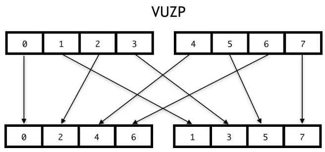
ARM NEON provides dozens of vector arithmetic and bitwise operations, vector
com-parison operations, permutation operations, and vector memory access operations. Vector
permutation operations in ARM NEON take on restricted forms with the shuffle pattern built
into the instruction opcode. Fig. 2.1 shows an example of the VUZP instruction, which can be
used to deinterleave vectors. Additionally special vector load and store operations combine
vector memory accesses with interleaving/deinterleaving by stride factors of two, three, and four[1].
ARM NEON registers can also be addressed as double-word registers instead of
quad-word registers. For example, the the double-quad-word registers
{d4, d5}
map to the quad-wordregister
q2
. This is useful when the full quad-word length is not necessary, and is also useful2.2. COMPILING FOR SIMD CHAPTER 2. VECTORIZATION FOR SIMD EXTENSIONS
Figure 2.1ARM NEON VUZP vector permutation instruction
2.2
Compiling for SIMD
The goal of a vectorizing compiler is to combine multiple scalar instruction to execute as
a vector instruction. To do so, the compiler must find data-level parallelism in the original
code that can be exploited. This data-level parallelism must be formed from independent
instructions that can execute concurrently in the same cycle. Additionally, the independent
instructions must be isomorphic (i.e. they must have the same opcodes).
Memory aliasing further complicates the compiler’s attempts to statically prove data
independence. For example, if the compiler cannot know whether a store and a load are
accessing the same memory location, then the compiler must conservatively assume that
the load depends on the store. Any instructions feeding the store would be considered in the
same dependence chain as instructions using the load result. This would prevent combining
any instructions in the dependence chain into the same SIMD operation.
2.3. LOOP VECTORIZATION CHAPTER 2. VECTORIZATION FOR SIMD EXTENSIONS
on by SIMD operations, it must first be packed into vector registers. After the SIMD operations
are complete, data may need unpacking for subsequent scalar operations or memory storage.
These packing and unpacking operations create an overhead for the vectorized code. The
compiler should reject transformations where the overhead outweighs the benefit.
In attempting to generate code where the vectorization benefit outweighs the packing/ un-packing overhead, the compiler can take multiple approaches. One approach is to reduce the
overhead of packing and unpacking. For example, the compiler can attempt to load or store
only contiguous vectors in memory to remove the overhead of packing. The compiler can
also minimize the packing overhead if it can form vectors that require data from memory in a
pattern that can be efficiently generated by the architecture’s vector permutation operations.
A second approach is to attempt to increase the benefit of paying the overhead. The
compiler can attempt to generate a longer chain of SIMD operations that use the same
packed data. If several SIMD operations use the same packed data, greater benefit can be
realized before unpacking the data.
2.3
Loop Vectorization
Loops tend to lend themselves to SIMD vectorization because of their tendency to perform
the same operation on multiple data. The basic goal of loop vectorization is to pack
iso-morphic instructions from different iterations of the same loop into a vector operation. The
number of iterations packed together corresponds to the vectorization factor. The
vector-ization factor is the number of data elements that can be operated on in a single vector
operation, and it is determined by the width of the SIMD architecture and the width of the
2.4. SLP VECTORIZATION CHAPTER 2. VECTORIZATION FOR SIMD EXTENSIONS
However, loop vectorization can be hindered by several different challenges. One key
challenge is inter-iteration data dependencies which prevent scheduling the operations
together in the same SIMD vector[6].
One case in which inter-iteration data dependences can be removed is when the data
dependence takes the form of a reduction variable[7]. In this case, the reduction operation must be associative, and there must be no uses of partial results. When a reduction loop is
vectorized, partial results are accumulated into a vector register, and these partial results
must be pairwise reduced after the loop is finished.
The memory access pattern for loops is important for efficient vectorization. The simplest
case for vectorization is a memory access pattern with a stride of one, but strided access
patterns can be efficiently supported on many architectures[9]. Another issue to consider is memory alignment, particularly with architectures that require it[2]. However, many modern ISAs support unaligned memory accesses, including ARM NEON, although extra
performance can be obtained if the alignment is known statically and specified with the
instruction[1].
Loop vectorization has traditionally focused on simpler, innermost, single-basic block
loops. However, techniques have been developed for dealing with more complicated
exam-ples. Techniques for vectorizing outer loops are presented in[8].
2.4
SLP Vectorization
Superword-level vectorization takes a different approach from loop vectorization. Instead of
forming isomorphic groups by combining loop iterations, SLP vectorization tries to combine
2.4. SLP VECTORIZATION CHAPTER 2. VECTORIZATION FOR SIMD EXTENSIONS
SLP vectorization can vectorize straight-line code, but it can also be used to vectorize
unrolled loops. This can be advantageous in certain circumstances. For example, sometimes
code is already partially manually unrolled by the programmer to perform more efficiently
for a particular compiler and architecture and requires loop re-rolling for efficient loop
vectorization. It can be the case that the programmer increases the stride distance of memory
accesses that were contiguous between loop iterations before manual unrolling. However,
SLP vectorization can operate without requiring re-rolling of such a loop[3].
The term SLP vectorization was introduced by Larsen and Amarasinghe. They compare
SLP to a restricted form of instruction-level parallelism[3]. ILP techniques allow multiple instructions on multiple data elements to execute simultaneously on hardware. ILP can be
dynamically scheduled and exploited by superscalar architectures, but a closer analogue to
SLP vectorization is VLIW instruction scheduling. Very-long instruction word architectures
allow the compiler to statically generate a valid schedule that will satisfy data-dependence
relationships. For example, an instruction that generates a value and another instruction
that uses the same value cannot be scheduled in the same VLIW word because the operand
to the second instruction will not be available before it is executed.
SIMD instruction set extensions impose similar restrictions on valid schedules. However,
due to the "single instruction" facet of the SIMD classification, the additional requirement of
instruction isomorphism is imposed.
The compiler pass in[3]begins by packing together memory accesses within a basic block that access adjacent memory locations. Since SIMD instruction set extensions provide
vector memory access operations that load from contiguous memory locations, adjacent
2.4. SLP VECTORIZATION CHAPTER 2. VECTORIZATION FOR SIMD EXTENSIONS
memory accesses, packing and unpacking of vector elements is necessary.
After memory accesses are packed together, the def-use chains (for loads) or use-def
chains (for stores) are followed to attempt to find additional packs of isomorphic operations
that use or feed the memory access pack, respectively. In this way, chains of vector operations
feeding each other can be formed to reduce packing and unpacking costs.
The algorithm by Larsen and Amarasinghe makes decisions based on local, greedy
heuris-tics. It does not necessarily generate the vector statements that have the most reuse and lead
to the most efficient vector chains. An algorithm published by Liu et al. attempts to make
more optimal decisions by considering potential reuse from the entire basic block when
forming SIMD groups[5]. This algorithm splits SLP vectorization into two steps: superword statement grouping and superword statement scheduling.
The unordered SIMD groups in Liu et al. are determined by starting with candidate groups
formed from independent, isomorphic instructions. Candidate groups may conflict with
each other if they contain the same instruction or form dependence cycles. SIMD groups are
selected from candidate groups by estimating the reuse across the entire basic block instead
of using the simpler, greedy heuristic from Larsen. The statement ordering within SIMD
groups is delayed until a later stage. At this point the cost of the vectorization transformation
CHAPTER
3
VECTORIZATION FROM REDUCTIONS
In this chapter I explain the type of kernel targeted for vectorization by my compiler pass
and the desired transformation to be performed by my compiler pass.
3.1
Example Kernel
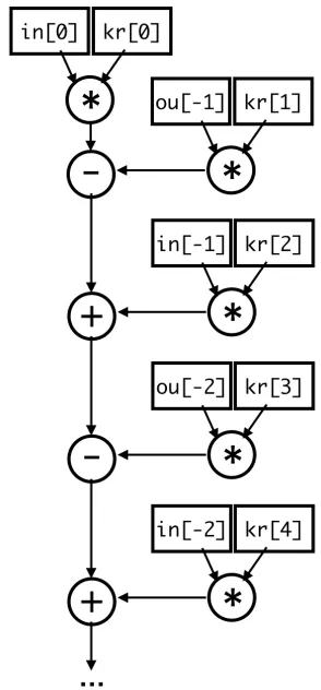
Fig. 3.1 shows an example kernel that my vectorizer targets. The code is based on a kernel
3.1. EXAMPLE KERNEL CHAPTER 3. VECTORIZATION FROM REDUCTIONS
loop is data-dependent on the previous iteration because the assigned
*output
becomesoutput[-1]
in the next iteration. Therefore, this kernel is not suitable for loop vectorization.However, from looking at the data-dependence graph in Fig. 3.1b, it is apparent that
data-independent, isomorphic instructions are present in the basic block, making this loop a
good candidate for SLP vectorization. Additionally, the loads from the
input
,output
, andkernel
arrays are placed to consecutive memory locations, meaning that the vectorizershould be able to generate vector loads, although it needs to also generate vector
permu-tation operations to get the loaded values in the correct vector lanes for the multiplication
operations.
Another key problem is that the multiplication operations feed a reduction chain, and
each operation in the chain is dependent on the previous operation. If we take this
data-dependence chain as is, it will severely inhibit the performance of the generated code because
we will be required to unpack every value from the multiplication operations to feed the
scalar chain.
However, if we assume that the addition and subtraction reduction chain in Fig. 3.1b are
associative, then we can separate the values from the multiplication operations into two
groups: the first group is all of the values that contribute positively to the final result, and the
other group is all of the values that contribute negatively. Within each group, then we can
treat all of the different pairs of multiplies as potential SIMD packs. In Fig. 3.1b, the multiplies
that are fed values from
input
array form the positive group, and those fed by theoutput
group, the negative.
The associativity of the reduction operation allows the vectorizer to generate an efficient
3.1. EXAMPLE KERNEL CHAPTER 3. VECTORIZATION FROM REDUCTIONS
while ( nSamples−−) { ∗output =
input[0] ∗ k e r n e l[0] − output[−1] ∗ k e r n e l[1] + input[−1] ∗ k e r n e l[2] − output[−2] ∗ k e r n e l[3] + input[−2] ∗ k e r n e l[4] − output[−3] ∗ k e r n e l[5] + input[−3] ∗ k e r n e l[6] − output[−4] ∗ k e r n e l[7]; ++output ;
++input ; }
(a)Code Listing (b)Scalar DDG
3.2. DESIRED TRANSFORMATION CHAPTER 3. VECTORIZATION FROM REDUCTIONS
3.2
Desired Transformation
In this section I will describe the desired transformation in more detail and provide examples
at the LLVM IR and ARM NEON levels.
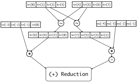
Figure 3.2Example Kernel Vectorized DDG
Fig. 3.2 show the desired form of the vector data-dependence graph, where the tildes
represent vector permutation operations. The vectorized and unvectorized codes are shown
in Fig. 3.3, and the corresponding LLVM intermediate representation (IR) is shown in Fig. 3.4
3.2. DESIRED TRANSFORMATION CHAPTER 3. VECTORIZATION FROM REDUCTIONS
permutations shown here can be implemented efficiently in the ARM NEON ISA. First,
data can be loaded and deinterleaved in one step using the
vld2
instruction. The examplevectorized ARM assembly in Fig. 3.3b is shown with a
vld1
instruction followed by avuzp
instruction because this is the assembly that the LLVM backend currently generates instead.
Using
vrev64
instructions, the floats inside each deinterleaved double word can be reversed.Finally
vext
instructions can be used to reverse the order of double words inside each quadword. The result is the two deinterleaved and fully reversed quad-word kernel vector registers
to be multiplied by input and output in Fig. 3.2.
After vectorization of the loads and multiplication operations, we then want to calculate
the final reduction value. Since we have the input values to the reduction in vector registers,
and the additive and subtractive reduction inputs are in separate quad-word registers, we
can generate vector operations to perform the reduction. We therefore begin with a vector
subtraction operation. This is shown on line 15 of Fig. 3.3b.
At this point there are no more quad-word registers that are part of the reduction, so we
must pairwise add the resulting vector to generate a scalar value. On ARM NEON we can
address the left- and right-half of the quad-word registers as double-word registers to add
together both halves into a vector of length two. This is illustrated on line 16 in Fig. 3.3b. A
vmov
instruction can then be used to place the right half of the double word into the samelane before issuing a final add to get the scalar result. This is shown on lines 17 and 18 of
3.2. DESIRED TRANSFORMATION CHAPTER 3. VECTORIZATION FROM REDUCTIONS
1 . LBB0_2 : @ %while. body 2 v l d r s8 , [r0]
3 subs r2 , r2 , #1 4 v l d r s10 , [r3] 5 v l d r s12 , [r3 , # 4] 6 v l d r s18 , [r1 , # 4] 7 vmul . f 3 2 d18 , d5 , d4 8 v l d r s0 , [r0 , #−4] 9 vmul . f 3 2 d17 , d6 , d9 10 v l d r s4 , [r3 , # 8] 11 v l d r s14 , [r3 , # 1 2] 12 vmul . f 3 2 d16 , d2 , d0 13 v l d r s16 , [r1]
14 v l d r s6 , [r0 , #−8] 15 vsub . f 3 2 d17 , d18 , d17 16 v l d r s8 , [r3 , # 1 6] 17 vmul . f 3 2 d18 , d7 , d8 18 v l d r s4 , [r1 , #−4] 19 vmul . f 3 2 d19 , d4 , d3 20 v l d r s6 , [r3 , # 2 0] 21 v l d r s2 , [r0 , #−12] 22 add r0 , r0 , #4
23 vadd . f 3 2 d16 , d17 , d16 24 v l d r s8 , [r3 , # 2 4] 25 vmul . f 3 2 d17 , d3 , d2 26 v l d r s0 , [r1 , #−8] 27 vsub . f 3 2 d16 , d16 , d18 28 vmul . f 3 2 d18 , d4 , d1 29 v l d r s2 , [r3 , # 2 8] 30 vadd . f 3 2 d16 , d16 , d19 31 vsub . f 3 2 d16 , d16 , d17 32 vmul . f 3 2 d17 , d1 , d0 33 vadd . f 3 2 d16 , d16 , d18 34 vsub . f 3 2 d0 , d16 , d17 35 v s t r s0 , [r1 , # 8] 36 add r1 , r1 , #4 37 bne . LBB0_2
(a)Unvectorized ARM Assembly
1 . LBB0_1 : @ %while. body 2 v l d 1 . 6 4 {d16 , d17}, [r12] 3 subs r2 , r2 , #1
4 v l d 1 . 6 4 {d18 , d19}, [r3] 5 vuzp . 3 2 q9 , q8
6 v l d 1 . 6 4 {d22 , d23}, [r0] 7 add r0 , r0 , #4
8 vrev64 . 3 2 q8 , q8 9 vrev64 . 3 2 q9 , q9
10 v l d 1 . 6 4 {d20 , d21}, [r1] 11 v e x t . 3 2 q8 , q8 , q8 , #2 12 v e x t . 3 2 q9 , q9 , q9 , #2 13 vmul . f 3 2 q8 , q8 , q10 14 vmul . f 3 2 q9 , q9 , q11 15 vsub . f 3 2 q8 , q9 , q8 16 vadd . f 3 2 d0 , d16 , d17 17 vmov . f 3 2 s2 , s1 18 vadd . f 3 2 d0 , d0 , d1 19 v s t r s0 , [r1 , # 1 6] 20 add r1 , r1 , #4 21 bne . LBB0_1
(b)Vectorized ARM Assembly
3.2. DESIRED TRANSFORMATION CHAPTER 3. VECTORIZATION FROM REDUCTIONS
while. body . l r . ph :
%a r r a y i d x 3 = g e t e l e m e n t p t r inbounds f l o a t∗ %kernel , i 3 2 1 %a r r a y i d x 6 = g e t e l e m e n t p t r inbounds f l o a t∗ %kernel , i 3 2 2
. . .
%a r r a y i d x 2 1 = g e t e l e m e n t p t r inbounds f l o a t∗ %kernel , i 3 2 6 %a r r a y i d x 2 5 = g e t e l e m e n t p t r inbounds f l o a t∗ %kernel , i 3 2 7
br l a b e l %while. body
while. body : ; preds = %while. body . l r . ph , %while. body %input . addr . 0 4 8 = phi f l o a t∗ [ %input , %while. body . l r . ph ],
[ %incdec . ptr28 , %while. body ]
%nSamples . addr . 0 4 7 = phi i 3 2 [ %nSamples , %while. body . l r . ph ], [ %dec , %while. body ]
%output . addr . 0 4 6 = phi f l o a t∗ [ %output , %while. body . l r . ph ], [ %incdec . ptr , %while. body ]
%dec = add i 3 2 %nSamples . addr . 0 4 7 , −1 %0 = load f l o a t∗ %input . addr . 0 4 8 , a l i g n 4 %1 = load f l o a t∗ %kernel , a l i g n 4
%mul = fmul f a s t f l o a t %1, %0
%a r r a y i d x 2 = g e t e l e m e n t p t r inbounds f l o a t∗ %output . addr . 0 4 6 , i 3 2 −1 %2 = load f l o a t∗ %a r r a y i d x 2 , a l i g n 4
%3 = load f l o a t∗ %a r r a y i d x 3 , a l i g n 4 %mul4 = fmul f a s t f l o a t %3, %2 %sub = fsub f a s t f l o a t %mul , %mul4
%a r r a y i d x 5 = g e t e l e m e n t p t r inbounds f l o a t∗ %input . addr . 0 4 8 , i 3 2 −1 %4 = load f l o a t∗ %a r r a y i d x 5 , a l i g n 4
%5 = load f l o a t∗ %a r r a y i d x 6 , a l i g n 4 %mul7 = fmul f a s t f l o a t %5, %4 %add = fadd f a s t f l o a t %sub , %mul7
. . .
%a r r a y i d x 2 0 = g e t e l e m e n t p t r inbounds f l o a t∗ %input . addr . 0 4 8 , i 3 2 −3 %12 = load f l o a t∗ %a r r a y i d x 2 0 , a l i g n 4
%13 = load f l o a t∗ %a r r a y i d x 2 1 , a l i g n 4 %mul22 = fmul f a s t f l o a t %13, %12 %add23 = fadd f a s t f l o a t %sub19 , %mul22
%a r r a y i d x 2 4 = g e t e l e m e n t p t r inbounds f l o a t∗ %output . addr . 0 4 6 , i 3 2 −4 %14 = load f l o a t∗ %a r r a y i d x 2 4 , a l i g n 4
%15 = load f l o a t∗ %a r r a y i d x 2 5 , a l i g n 4 %mul26 = fmul f a s t f l o a t %15, %14 %sub27 = fsub f a s t f l o a t %add23 , %mul26
s t o r e f l o a t %sub27 , f l o a t∗ %output . addr . 0 4 6 , a l i g n 4
%incdec . p t r = g e t e l e m e n t p t r inbounds f l o a t∗ %output . addr . 0 4 6 , i 3 2 1 %incdec . p t r 2 8 = g e t e l e m e n t p t r inbounds f l o a t∗ %input . addr . 0 4 8 , i 3 2 1 %tobool = icmp eq i 3 2 %dec , 0
br i 1 %tobool , l a b e l %while. end . l o o p e x i t , l a b e l %while. body
3.2. DESIRED TRANSFORMATION CHAPTER 3. VECTORIZATION FROM REDUCTIONS
while. body . l r . ph :
%a r r a y i d x 1 3 = g e t e l e m e n t p t r inbounds f l o a t∗ %kernel , i 3 2 4 br l a b e l %while. body
while. body : ; preds = %while. body . l r . ph , %while. body %input . addr . 0 4 8 = phi f l o a t∗ [ %input , %while. body . l r . ph ],
[ %incdec . ptr28 , %while. body ]
%nSamples . addr . 0 4 7 = phi i 3 2 [ %nSamples , %while. body . l r . ph ], [ %dec , %while. body ]
%output . addr . 0 4 6 = phi f l o a t∗ [ %output , %while. body . l r . ph ], [ %incdec . ptr , %while. body ]
%dec = add i 3 2 %nSamples . addr . 0 4 7 , −1
%a r r a y i d x 2 0 = g e t e l e m e n t p t r inbounds f l o a t∗ %input . addr . 0 4 8 , i 3 2 −3 %b v s v e c p t r = b i t c a s t f l o a t∗ %a r r a y i d x 2 0 to <4 x f l o a t>∗
%bvsloadvec = load <4 x f l o a t>∗ %bvsvecptr , a l i g n 8
%a r r a y i d x 2 4 = g e t e l e m e n t p t r inbounds f l o a t∗ %output . addr . 0 4 6 , i 3 2 −4 %bvsvecptr49 = b i t c a s t f l o a t∗ %a r r a y i d x 2 4 to <4 x f l o a t>∗
%bvsloadvec50 = load <4 x f l o a t>∗ %bvsvecptr49 , a l i g n 8 %bvsvecptr51 = b i t c a s t f l o a t∗ %k e r n e l to <4 x f l o a t>∗
%bvsloadvec52 = load <4 x f l o a t>∗ %bvsvecptr51 , a l i g n 8 %bvsvecptr53 = b i t c a s t f l o a t∗ %a r r a y i d x 1 3 to <4 x f l o a t>∗
%bvsloadvec54 = load <4 x f l o a t>∗ %bvsvecptr53 , a l i g n 8 %b v s s h u f f l e f r o m = s h u f f l e v e c t o r <4 x f l o a t> %bvsloadvec52 ,
<4 x f l o a t> %bvsloadvec54 , <4 x i32> <i 3 2 7 , i 3 2 5 , i 3 2 3 , i 3 2 1> %b v s s h u f f l e f r o m 5 5 = s h u f f l e v e c t o r <4 x f l o a t> %bvsloadvec52 ,
<4 x f l o a t> %bvsloadvec54 , <4 x i32> <i 3 2 6 , i 3 2 4 , i 3 2 2 , i 3 2 0> %bvsbovec = fmul <4 x f l o a t> %bvsshufflefrom55 , %bvsloadvec
%bvsbovec56 = fmul <4 x f l o a t> %b v s s h u f f l e f r o m , %bvsloadvec50 %rvreducedop = fsub <4 x f l o a t> %bvsbovec , %bvsbovec56
%r v p a i r w i s e l = s h u f f l e v e c t o r <4 x f l o a t> %rvreducedop , <4 x f l o a t> undef , <2 x i32> <i 3 2 0 , i 3 2 1> %r v p a i r w i s e r = s h u f f l e v e c t o r <4 x f l o a t> %rvreducedop ,
<4 x f l o a t> undef , <2 x i32> <i 3 2 2 , i 3 2 3>
%r v p a i r w i s e o p = fadd <2 x f l o a t> %r v p a i r w i s e l , %r v p a i r w i s e r %r v p a i r w i s e l 5 7 = e x t r a c t e l e m e n t <2 x f l o a t> %rvpairwiseop , i 3 2 0 %r v p a i r w i s e r 5 8 = e x t r a c t e l e m e n t <2 x f l o a t> %rvpairwiseop , i 3 2 1 %rvpairwise op59 = fadd f l o a t %r v p a i r w i s e l 5 7 , %r v p a i r w i s e r 5 8
s t o r e f l o a t %rvpairwiseop59 , f l o a t∗ %output . addr . 0 4 6 , a l i g n 4 %incdec . p t r = g e t e l e m e n t p t r inbounds f l o a t∗ %output . addr . 0 4 6 , i 3 2 1 %incdec . p t r 2 8 = g e t e l e m e n t p t r inbounds f l o a t∗ %input . addr . 0 4 8 , i 3 2 1 %tobool = icmp eq i 3 2 %dec , 0
br i 1 %tobool , l a b e l %while. end . l o o p e x i t , l a b e l %while. body
CHAPTER
4
IMPLEMENTATION
The vectorizer is implemented as a compiler pass in LLVM 3.6. The pass is inserted into the
LLVM pass manager framework after the in-tree SLP vectorization pass. In this section I will
4.1. REDUCTION IDENTIFICATION CHAPTER 4. IMPLEMENTATION
4.1
Reduction Identification
The vectorizer looks for potential vectorization opportunities by searching for chains of
associative operations within a single basic block that form a reduction. It searches each
basic block from bottom to top looking for compatible operations that could be the final
operation (output) of a reduction chain. It then recursively searches the operands of the
compatible instruction for additional compatible instructions that meet the requirements
discussed in this section. When compatible operands are found they are added to the chain,
and their operands are in turn recursively searched.
When an operand is reached that is not compatible, or which is not in the original basic
block, the recursion stops. The incompatible instruction or constant is recorded as an input
to the reduction chain. These input values to the reduction chain will be leveraged by the
vectorizer in the manner described in the next section.
A key requirement of the associative reduction chain is that the intermediate values have
no uses other than the next instruction in the chain. Only the final, fully reduced value may
have other uses.
The reduction identification pseudocode is shown in Algorithms 1 and 2.
4.1.0.0.1 Reduction Operations
The vectorizer supports integer and floating-point addition, subtraction, and multiplication.
For these operations, it currently support scalar types that correspond to those supported
by ARM. Integer types vectorized are 8-, 16-, 32-, and 64-bit integers. Floating-point types
4.1. REDUCTION IDENTIFICATION CHAPTER 4. IMPLEMENTATION
Algorithm 1:processBasicBlock()
Input: A basic block,BB
Result: Scalar operations feeding reductions are replaced with vector operations, and vector reduction code is added
foreachinstruction I in BB in reverse orderdo
ifI in the set of instructions previously checked by buildReduction()then
continue;
ifI is not a compatible reduction operationthen
continue;
(RInputs, RSubInputs, RBinOps)←buildReduction(I, false);
ifRInputs < VF && RSubInputs < VFthen
continue;
VTree←buildTree(RInputs);
VSubTree←buildTree(RSubInputs);
if!VTree || !VSubTreethen
continue;
4.1. REDUCTION IDENTIFICATION CHAPTER 4. IMPLEMENTATION
Algorithm 2:buildReduction()
Input: A binary operator in the reduction,BinOp; Whether BinOp contributes negatively to the final reduction,IsNeg
Result: A list of inputs feeding the reduction to this operator,RInputs; A list of inputs feeding the reduction to this operator negatively,RSubInputs; A list of reduction operators feeding the reduction to this operator,RBinOps
foreachvalue Def in BinOp.Defsdo
ifcompatibleForReduction(BinOp, Def ) && hasOneUse(Def )then
RBinOps.insert(Def );
ifisRightOperand(Def ) && isSubtract(BinOp)then
buildReduction(Def, !IsNeg);
else
buildReduction(Def, IsNeg);
else
ifIsNegthen
RSubInputs.insert(Def );
else
4.1. REDUCTION IDENTIFICATION CHAPTER 4. IMPLEMENTATION
4.1.0.0.2 Subtraction Support
Subtraction as well as mixed addition/subtraction reduction chains are supported. When the reduction incorporates subtraction, the pass keeps track of which input values to the chain
contribute positively and which contribute negatively.
Positive and negative inputs are placed into separate "pools" for vectorization. The
vectorizer must vectorize these inputs separately in order to efficiently reduce them later by
using vector addition and subtraction without extracting the values. However, the addition
and subtraction inputs still form roots to the same tree, allowing my pass to detect loads that
should be deinterleaved to each side, such as the example in the previous chapter.
4.1.0.0.3 Floating-Point Associativity
Floating-point support requires the "fast" fast-math flag on the instruction in the LLVM IR,
which allows for additional flexibility in reordering floating-point operations that violate the
IEEE 754 standard. The ability to change the associativity and ordering of the operations
is necessary for this vectorization pass. Additionally, the ARM NEON unit is not IEEE
754-compliant. For example, it flushes denormalized numbers to zero.
The fast-math flags in the LLVM IR are set by the Clang frontend. These can be enabled
during complation by passing compile flags such as "-ffast-math" and
"-funsafe-math-optimizations." The build systems for some programs pass these options to the compiler by
4.2. VECTORIZABLE TREE CONSTRUCTION CHAPTER 4. IMPLEMENTATION
4.2
Vectorizable Tree Construction
The vectorizer takes the reduction inputs identified in the previous step and attempts to build
a bottom-up tree with each node of the tree containing isomorphic instructions. Because the
roots are already split between additive and subtractive inputs, and the roots themselves likely
consist of different types of instructions that must be split apart, the generated structure is
more accurately described as multiple trees, or a forest. The tree enables the pass to estimate
the most optimal packing for the reduction inputs. The highest entries in the tree correspond
to a longer chain of isomorphic instructions resulting in greater vectorization benefit.
4.2.1
Tree Structure
The vectorizable tree consists of a list of entries. Each entry contains groups, where each
group consists of unordered isomorphic instructions that are vectorizable. The tree is built
from the bottom up starting from the root groups that correspond to the reduction inputs.
Each group may have a child entry or entries (for binary operations) that correspond to
the operands of the group. In each group, the use-def chains of the scalar instructions are
followed, and the tree construction process attempts to place the defs of the scalars in the
current group into new child entries in the tree.
4.2.2
Group Creation
The new values from the operands of the root instructions are placed into a new child entry,
and now the operand values must be sorted into isomorphic groups. New groups are created
4.2. VECTORIZABLE TREE CONSTRUCTION CHAPTER 4. IMPLEMENTATION
Algorithm 3:buildTree()
Input: The scalar defs from the parent group,Defs; The users in the parent group,
TreeUsers
Result: A vectorizable tree,VTree
(Groups, Gathered)=createGroups(Defs);
foreachgroup G in Groupsdo foreachvalue V in Gdo
if!checkDependencies(V, G, TreeUsers)then
return NULL;
ifG is a group of load instructionsthen
VTree.addLeafNode(G); break;
ifG is a group of commutative binary instructionsthen
sortDefsByOpcode(G);
fori = 0tonum operands in G’s instruction typedo
Defs←operandsAtPosition(G, i); SubTree←buildTree(Defs, G);
ifSubTree != NULLthen
VTree.addSubTree(SubTree);
else
return NULL;
4.2. VECTORIZABLE TREE CONSTRUCTION CHAPTER 4. IMPLEMENTATION
Algorithm 4:createGroups()
Input: The scalar defs feeding the parent group,Defs
Result: List of isomorphic groups,Groups; List of instructions to gather,Gathered
foreachvalue I in Defsdo
broadcast=false;
foreachvalue J in Defs starting at Ido ifI == Jthen
Defs.remove(J); Gathered.insert(I); broadcast=true;
ifbroadcast == truethen
continue;
ifisConstant(I) || inTree(I)then
Gathered.insert(I); continue;
ifI is instructionthen
if(basicBlock(I) != Reduction BB) || !vectorizableOp(I)then
Gathered.insert(I); continue;
Groups[opcode].insert(I);
foreachgroup G in Groupsdo ifG.size() < VFthen
4.2. VECTORIZABLE TREE CONSTRUCTION CHAPTER 4. IMPLEMENTATION
than the minimum vectorization factor for the data type, and the process of forming child
entries for the new group recurses.
There are several conditions that may terminate tree growth. When instructions are not
vectorizable, or there are not enough isomorphic instructions of a certain type, then those
instructions do not form new groups. Also, when the use-def chain reaches instructions
outside the current basic block or when it reaches constants, tree growth is terminated. These
are considered as values that will be gathered.
Load instructions get placed into new groups in the tree, but they terminate tree growth
as well.
The pseudocode for tree building and the group splitting is shown in Algorithms 3 and 4.
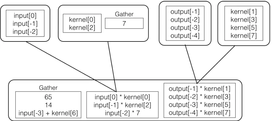
Example code and the created tree is shown in Fig. 4.1.
4.2.3
Data-Dependence Restrictions
Some restrictions are placed on the structure of the data-dependence graph to simplify the
pass and enable efficient vector formation.
4.2.3.0.4 Group Self Dependency
The values within each group are intended as candidates for vector formation. Therefore, it is
important that values within a group do not have dependencies on one another. The uses of
each value are recursively checked until reaching a reduction operation or beyond the basic
block. If another value in the same group is reached, then the group is not formed and the
vectorization is cancelled.
4.2. VECTORIZABLE TREE CONSTRUCTION CHAPTER 4. IMPLEMENTATION
of the basic block. However, during testing some very large basic blocks with large def-use
chain fan-out were discovered. For this reason, a limit on recursion depth was placed at 20
levels deep to prevent excessive run time. If this limit is exceeded, vectorization is cancelled.
4.2.3.0.5 Overlapping Trees
The use-def chains in the vectorizable tree may merge together instead of diverging into new
child entries. When a new group is formed and its def-use chains are being traversed, it is
checked whether any values entered into the tree other than those in the parent group are
reached or whether there are any uses outside the tree that reconverge with the parent entry.
If this happens, vectorization is cancelled. If this were not enforced, then the vectorizable
tree would not be a tree at all – it would be a more general acyclic graph structure that would
complicate vectorization.
The pseudocode for the checks for groups self dependency and overlapping trees is shown
in Algorithm 5.
4.2.3.0.6 Broadcast Values
If two users currently in a tree group form a new def group with duplicate values, this is
con-sidered a broadcast from the child group. Broadcasted values are similar to the overlapping
tree case, but the use-def chain merging is within the same parent group instead of between
them. Broadcasted values are supported, but they are removed from any child groups and
4.2. VECTORIZABLE TREE CONSTRUCTION CHAPTER 4. IMPLEMENTATION
Algorithm 5:checkDependencies()
Input: The value to check dependencies for,Value; A list of values in the same operand group as Value,GroupList; The users in the parent group,TreeUsers
Result: Whether the dependencies allow for vectorization
foreachvalue I in Value.Usersdo
ifbasicBlock(I) != Reduction BBthen
continue;
ifGroupList.contains(I)then
return false;
ifinTree(I) && !TreeUsers.contains(I)then
return false;
else
// call with TreeUsers empty
return checkDependencies(I,{}); return true;
4.2.3.0.7 Memory Aliasing
Memory aliasing issues must be considered before load vectors can be formed. Consider
a scalar store that is present in the instruction stream between two scalar loads that are
candidate for vectorization. If static analysis reveals that the store may alias with either, then
the compiler will not know whether there is a WAR hazard with the first load or a RAW hazard
with the second. Therefore the compiler will not be able to guarantee a valid schedule for the
vector load operation, and the vector formation must be cancelled.
Memory aliasing issues are actually checked during the scheduling phase after vector
formation, and at the build tree stage they are assumed not to exist. Currently a naive policy
is implemented that considers all accesses as may-alias. In the future the vectorizer should
4.3. VECTOR FORMATION CHAPTER 4. IMPLEMENTATION
4.2.4
Auxiliary Data Structures
Several other data structures are constructed during tree formation. Each scalar value in the
tree is inserted into two maps. The first maps each value to it’s group in the tree and is used
for the data dependence checks discussed previously. The second maps each value to the
root value that it grew from through the use-def chain. Because of the no-overlapping-tree
and broadcast restrictions, each value in the tree maps to exactly one root (input to the final
reduction chain).
Groups are inserted into a set that is ordered by height from the root vector. This is helpful
in the next step where we start attempting to form vectors from the greatest height in the tree
to form the longest vector chains possible.
Load instructions within each group are separated into lists based on their base pointer,
and a map from base pointer to it’s loads is created within each group. This is helpful because
we later look for consecutive memory accesses only between accesses with the same base
pointer to improve efficiency. Also, a structure stores a map from each base pointer to
all groups containing a memory access with that base pointer for efficiently checking for
interleaving between groups later.
4.3
Vector Formation
After generating the vectorizable tree, the pass has many possible candidates for forming
vec-tor operations from each entry group. The vecvec-tor formation stage decides which operations
from each group should be placed in the same vector, and the ordering of the statements
4.4. VECTOR SCHEDULING AND IR GENERATION CHAPTER 4. IMPLEMENTATION
Because each scalar value in the tree maps to a single scalar root, that root and all the
values associated with it can be thought of as a virtual lane. Whenever values are packed into
a superword, all values in their virtual lanes must either be packed in the same manner, or a
vector permutation operation must be planned.
Vectors are formed in three stages. The first stage looks for contiguous load vectors within
each group. The second stage looks for contiguous load vectors that can be deinterleaved by
a factor of two between two load groups. The third stage simply attempts to generate vector
chains from the remaining lanes that will be fed by gathers from scalar operations.
My pass attempts to form vectors corresponding to the groups that reach highest in the
tree first. This ensures that generated vectors will have longer vector def-use chains, resulting
in more vector operations and more benefit from the packed vectors.
When a vector is formed (e.g. from contiguous loads) other loads in other groups
corre-sponding to the same roots are checked for special patterns than can be vectorized. If the
other loads are also contiguous, my pass adds another contiguous vector for scheduling.
If the other loads are reversed, my pass adds a contiguous load and a vector permutation
instruction for reversal. If the loads are stride two or reversed stride two, they are added to a
special list. This list is later checked for strided accesses that can be combined to form
con-tiguous accesses, allowing for the generation of vector load operations with deinterleaving
vector permutation operations.
4.4
Vector Scheduling and IR Generation
The vector formation stage chooses vectors and orders superword statements within them.
4.4. VECTOR SCHEDULING AND IR GENERATION CHAPTER 4. IMPLEMENTATION
begins.
The goals for scheduling are to 1) replace scalar IR operations with vector IR operations,
2) make sure that definitions dominate all their uses, 3) create gather operations to place
unvectorized inputs to vector operations into, 4) create scatter operations for unvectorized
uses of vectorized instructions, 5) create supported vector permutation operations after
vector load operations feeding vectors that are strided or reversed, and 6) generate an efficient
vector reduction sequence to obtain the scalar result needed.
The approach I take to scheduling the IR is relatively simple. Vector operations are placed
after the last scalar operation that they originally contained, ensuring that all definitions
are available. Operations that depend on the vector operations, but which themselves are
not vectorized, are delayed until after the vector operation is scheduled and inserted into a
pending set. When a vector instruction is scheduled its users are checked to see of they are in
the pending set. If a user is in the pending set, and it is not waiting on any other operand,
then an
extractelement
instruction is generated for the scalar user, and the scalar user isscheduled with its operand replaced with the
extractelement
instruction.When a vector is generated, but its operands do not match another vector nor a
per-mutation communicated from the vector formation stage, it’s operands must be gathered.
The scheduler does this automatically inserting
insertelement
instructions to build theneeded vector operand.
The final step is reducing the vectors together, and the pairwise reducing the vector lanes
to the final scalar result. My vectorizer support multiple sizes of vectors that match up with
ARM NEON support. To generate an efficient reduction sequence, all quad words are reduced
4.4. VECTOR SCHEDULING AND IR GENERATION CHAPTER 4. IMPLEMENTATION
that may have been created during the vector formation stage are reduced into the chain.
Finally, the double-word vector is pairwise-reduced to a scalar value and any leftover scalars
4.4. VECTOR SCHEDULING AND IR GENERATION CHAPTER 4. IMPLEMENTATION
(a)Tree Structure
while ( nSamples−−) { ∗output =
65 + 14
+ input[0] ∗ k e r n e l[0]
− output[−1] ∗ k e r n e l[1]
+ input[−1] ∗ k e r n e l[2]
− output[−2] ∗ k e r n e l[3]
+ input[−2] ∗ 7
− output[−3] ∗ k e r n e l[5]
+ input[−3] + k e r n e l[6]
− output[−4] ∗ k e r n e l[7];
++output ;
++input ;
}
(b)Code Listing
CHAPTER
5
EVALUATION
5.1
Benchmarks
5.1.1
Kernel #1
5.1.1.0.8 Description
The IIR filter kernel is taken from the filterYule() function in gain_analysis.c in the LAME MP3
5.1. BENCHMARKS CHAPTER 5. EVALUATION
It must be noted that this example is slightly modified from the original source. The
original source included a small constant in the reduction with a comment indicating that it
was intended to prevent slowdown due to floating-point denormalization. However, there was
no
’f’
specifier after the literal constant in the C code, which promoted every operation inthe basic block to double-precision floating-point type. On some architectures vectorization
would still be possible, but ARM NEON does not support double-precision floating-point
math. For this reason I changed the constant to a single-precision floating-point literal value
in the C code.
while ( nSamples−−) { ∗output = 1e−10 f
+ input[0] ∗ k e r n e l[0]
− output[−1] ∗ k e r n e l[1]
+ input[−1] ∗ k e r n e l[2]
− output[−2] ∗ k e r n e l[3]
+ input[−2] ∗ k e r n e l[4]
− output[−3] ∗ k e r n e l[5]
+ input[−3] ∗ k e r n e l[6]
− output[−4] ∗ k e r n e l[7]
+ input[−4] ∗ k e r n e l[8]
− output[−5] ∗ k e r n e l[9]
+ input[−5] ∗ k e r n e l[1 0]
− output[−6] ∗ k e r n e l[1 1]
+ input[−6] ∗ k e r n e l[1 2]
− output[−7] ∗ k e r n e l[1 3]
+ input[−7] ∗ k e r n e l[1 4]
5.1. BENCHMARKS CHAPTER 5. EVALUATION
+ input[−8] ∗ k e r n e l[1 6]
− output[−9] ∗ k e r n e l[1 7]
+ input[−9] ∗ k e r n e l[1 8]
− output[−10] ∗ k e r n e l[1 9]
+ input[−10] ∗ k e r n e l[2 0]; ++output ;
++input ;
}
Loop vectorization of this kernel is inhibited by a loop-carried data dependence in the
output
array. Each iteration of the loop is used to compute a new element in theoutput
array, which is then used for the calculation of subsequent outputs.
In this example, the
kernel
array is loop-invariant as used in the larger application (as isthe shifting
input
array). However, the compiler cannot prove this because all of the arraypointers are passed as parameters with no guarantees on aliasing. Therefore, every value
from every array is loaded on every iteration.
5.1.1.0.9 Transformation
My pass identifies the final addition that is stored to
*output
as the result of a reductionchain. All values added to the reduction are placed in the additive group, and all values
subtracted are placed in the subtractive group.
During vector formation, my pass first identifies the contiguous loads in the groups
feeding the left sides of the multiplication operations. For example,
output[-10 .. -7]
is a contiguous load inside the same load group. Since my pass starts by looking within the
5.1. BENCHMARKS CHAPTER 5. EVALUATION
– is not initially seen as contiguous. However, in the absence of contiguous loads within a
group my pass would have continued to search for interleaving between groups.
When contiguous loads such as
output[-10 .. -7]
are found the vector formationstage begins forming vectors from values in groups that correspond to the load group’s users
and the other operands to it’s users (in this example, the kernel operands to the multiply
instructions). When this process attempts to form the kernel vector it notes a reversed stride
two pattern and adds the potential partial vector to the list of reversed stride two requested
vectors. When forming the vectors from
input[-10 .. -7]
the vectorizer does the same.Finally, when the vectorizer is attempting to match together reversed stride two requested
loads it finds the contiguous vector
kernel[13 .. 20]
and invokes the appropriatema-chinery to form the vector load and request the appropriate vector permutation instructions
to deinterleave and reverse the loaded values to be fed to the multiplication vector operations.
My pass generates 128-bit vector operations for the lanes corresponding to
output[-10
.. -7]
,input[-10 .. -7]
,output[-6 .. -3]
, andinput[-6 .. -3]
. It generates64-bit vector operations for lanes corresponding to
output[-2 .. -1]
andinput[-2 ..
-1]
. Finally, the lanes corresponding toinput[0]
and the literal constant remain as scalars.My pass then generates vector reduction operations to reduce to the final value as
dis-cussed previously.
5.1.2
Kernel #2
5.1.2.0.10 Description
The FIR filter kernel is taken from the vbrpsy_attack_detection() function in psymodel.c in
5.1. BENCHMARKS CHAPTER 5. EVALUATION
The source code for the inner loop of this kernel appears to be amenable to loop-style
vectorization (NSFIRLEN is a macro constant). Notwithstanding, in my test LLVM’s loop
vectorizer did not vectorize this loop at -O3. However, it did unroll the inner loop, leaving
an opportunity for my vectorization pass to operate at a single-basic block level on the
reduction.
The kernel computes 576 output elements by applying the filter coeffiecients in the
statically defined array fircoef. The filter is applied to the input values passed via function
parameter in firbuf.
Each iteration of the outer loop corresponds to a new output element. Each iteration of
the inner loop computes a portion of the final sum.
Unlike the previous kernel, each iteration of the outer loop is independent. This makes
loop vectorization of the outer loop conceptually possible as well (after unrolling of the inner
loop). However, LLVM does not make this transformation at -O3 either.
f o r ( i = 0 ; i < 5 7 6 ; i++) { FLOAT sum1 , sum2 ;
sum1 = f i r b u f[i + 1 0];
sum2 = 0 . 0 ;
f o r ( j = 0 ; j < ( ( NSFIRLEN − 1 ) / 2 ) − 1 ; j += 2 ) { sum1 += f i r c o e f[j]
∗ ( f i r b u f[i + j] + f i r b u f[i + NSFIRLEN − j]) ;
sum2 += f i r c o e f[j + 1]
∗ ( f i r b u f[i + j + 1] + f i r b u f[i + NSFIRLEN − j − 1]) ;
}
ns_hpfsmpl[chn] [i] = sum1 + sum2 ;
5.1. BENCHMARKS CHAPTER 5. EVALUATION
Although the reduction only appears to have additions, this is actually an addition / subtraction mixture in the generated LLVM IR. This is because LLVM perfoms constant
prop-agation on the fircoef array, and it appears to change the negative coeffiecients to positive
constants and replace some of the floating-point additions with subtraction operations.
5.1.2.0.11 Transformation
Once my pass executes LLVM has performed the constant value propagation and unrolled
the inner loop completely. This allows my pass to start at the value operand to the store in
the ns_hpfsmpl array.
Everything added to the sum1 and sum2 variables is treated as a reduction input and this
forms the roots of the vectorizable tree. Because of the constant value propagation, when
the fircoef element is positive the input is added to the addition group, and when fircoef is
negative the input is added to the subtraction group.
Most of the inputs, with the exception of the initial assignments to sum1 and sum2, are
multiply instructions. Thus, the largest groups at the root level of the tree are the multiply
groups. The addition of the two locations in firbuf on the right side of the multiplications
form more isomorphic groups in the next level up in the tree.
My vectorizer starts looking for contiguous load chains at the highest levels of the tree
and first finds the<firbuf[i+NSFIRLEN - j - 1], firbuf[i+NSFIRLEN - j]>chains. It forces these columns of the tree into vectors and also discovers that the corresponding<firbuf[i
+j+1], firbuf[i+j]>vectors match the reversed pattern and generate a vector load with a
reversal shuffle operation.
5.1. BENCHMARKS CHAPTER 5. EVALUATION
filter coefficients are generated to feed the vector multiplication of the coeffiecients with the
added firbuf vectors. My pass then generates the vector reduction operations as described
previously to add the vectors and to generate the final scalar value to store to the ns_hpfsmpl
array.
5.1.3
Kernel #3
This kernel is taken from the window_subband() function in newmdct.c in the LAME MP3
encoder.
5.1.3.0.12 Description
In this kernel the variable s and t form reduction chains. There is more similar code in this
kernel, but it is omitted for brevity. The reductions in this kernel have a contiguous loads to
the wp array.
f o r ( i = −15; i < 0 ; i++) { FLOAT w, s , t ;
w = wp[−1 0];
s = x2[−224] ∗ w;
t = x1[2 2 4] ∗ w;
w = wp[−9];
s += x2[−160] ∗ w;
t += x1[1 6 0] ∗ w;
w = wp[−8];
s += x2[−96] ∗ w;
5.2. RESULTS CHAPTER 5. EVALUATION
w = wp[−7];
s += x2[−32] ∗ w;
t += x1[3 2] ∗ w;
w = wp[−6];
. . .
wp += 1 8 ;
x1−−;
x2++;
}
5.1.3.0.13 Transformation
Because the vector formation stage looks for contiguous loads first, vectors are formed
from the inputs that access contiguous locations in the wp array. However, the x1 and x2
array accesses cannot form contiguous vector load or any supported reversed or interleaved
pattern. Therefore, separate gather loads must be created for accesses to x1 and x2 to get
them in the vector for multiplication with the wp values. Vector multiplies are created and
the multiplication are reduced in the manner discussed previously.
Although vector multiplications are created and vector loads are created for the right
operands to the multiplies, the average vector chain length is shorter for this kernel than the
other kernels, and the loads to x1 and x2 are not vectorized.
5.2
Results
The LAME MP3 encoder was compiled for an ARM Cortex-A8 BeagleBone Black system with
5.2. RESULTS CHAPTER 5. EVALUATION
-O3
flag was passed to allow other optimizers – including the LLVM loop and SLP vectorizers –to run.
5.2.1
Speedup
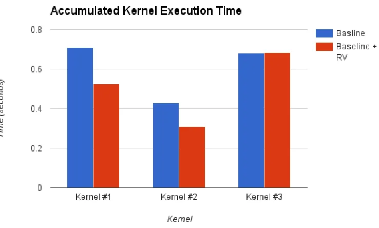
Figure 5.1Kernel Speedup
Timing code was inserted around the kernels in the LAME MP3 encoder. The timing code
accumulated the total time for all invocations of the kernels during a single run. LAME was
then asked to encode a WAV file to MP3 format five times. The average result from the five
runs were averaged. The results of both the baseline case and baseline plus my vectorizer
5.2. RESULTS CHAPTER 5. EVALUATION
Kernel #1 and kernel #2 show approximately 25% speedup. Kernel #3 shows no speedup.
This is probably due to the gathered loads and the shorter average vector chain length.
LAME overall showed a 1.85% speedup in MP3 encoding using default settings.
5.2.2
Code Size
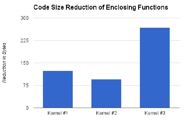
Figure 5.2Code Size Reductions
My vectorizer can reduce code size by replacing multiple scalar instructions with SIMD
instructions. The functions containing the above kernels were measured using the GNU
nm
utility with and without my vectorization pass. The results are reported in Fig. 5.2.
5.2. RESULTS CHAPTER 5. EVALUATION
pass reduced the code size by 1,224 bytes to 1,043,522 bytes.
5.2.3
Compilation Efficiency
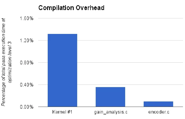
Figure 5.3Percentage of Pass Execution Time
To measure the efficiency of my compiler pass I recompiled in release mode and ran with
Clang’s
-ftime-report
option. The generated report shows the measured time for eachcompiler pass ran by the pass manager.
I collected timing reports for three different source files. The first one included Kernel
#1 and a small
main()
function designed to feed it random data. The second is the5.2. RESULTS CHAPTER 5. EVALUATION
The third file,
encoder.c
, also contains a vectorized kernel, but the reduction chain in thisexample is shorter and the generated tree is smaller.
These results show that my vectorization pass is reasonably efficient and in line with the
CHAPTER
6
CONCLUSION
6.1
Related Work
The algorithm presented by Larsen in[3]starts with consecutive memory accesses and builds vectorized chains. It is based on local, greedy heuristics which may not make good decisions
that lead to efficient pack sets, and it does not handle the vector permutations needed to
efficiently vectorize the examples in this paper. It also does not consider starting packs from
6.2. FINAL REMARKS CHAPTER 6. CONCLUSION
The work by Liu et al. [5] can generate vector permutations when a group must be reordered during scheduling. However, it would not appear to handle the types of
deinter-leaving operations needed to support Kernel #1, where the
kernel
array is deinterleavedand distributed to multiply with the
input
andoutput
arrays. It also does not considerreductions. However, like my pass it does group potential SIMD operations together first and
delay ordering the enclosed SIMD statements until later.
The LLVM SLP vectorizer works in a bottom-up manner, typically starting from
con-tiguous stores and forming vector chains. It also includes some functionality (disabled by
default in LLVM 3.6) for vectorizing starting from reduction chains. However, several factors
currently prevent it from efficiently vectorizing this kernel. One reason is that it currently
only handles addition chains, and no other operations such as subtraction. Another, more
fundamental problem is that its bottom-up vectorizer expects to receive the packed roots to
begin the vector formation from the bottom. However, unlike with consecutive store chains,
it is impossible to determine the best grouping and ordering from the bottom at a reduction.
To determine the best grouping and ordering of the input operations to the reduction, it is
necessary to determine which loads are feeding which reduction values to reduce the need
for vector permutations and packing/unpacking instructions. It is also beneficial to create packs from the reduction values that will have longer vectorizable use-def chains, which my
pass is able to do by measuring tree height before making packing decisions.
6.2
Final Remarks
In this thesis I have presented a SLP vectorizer that leverages the associativity of reduction
6.2. FINAL REMARKS CHAPTER 6. CONCLUSION
my vectorizer for selected kernels, and I have shown that it can produce speedup and
reduction in code size without excessive compilation overhead.
Future work should evaluate this pass on additional applications. The pass can also be
adopted to work with store chains as roots as well as reduction operations. Finally, additional
benefit is likely obtainable for some kernels by unrolling loops before running my pass to
REFERENCES
[1] ARM Architecture Reference Manual: ARMv7-A and ARMv7-R edition. ARM. 2012.
[2] Eichenberger, A. E. et al. “Vectorization for SIMD Architectures with Alignment Con-straints”.Proceedings of the ACM SIGPLAN 2004 Conference on Programming Lan-guage Design and Implementation. PLDI ’04. Washington DC, USA: ACM, 2004, pp. 82– 93.
[3] Larsen, S. & Amarasinghe, S. “Exploiting Superword Level Parallelism with Multimedia Instruction Sets”.Proceedings of the ACM SIGPLAN 2000 Conference on Programming Language Design and Implementation. PLDI ’00. Vancouver, British Columbia, Canada: ACM, 2000, pp. 145–156.
[4] Lattner, C. & Adve, V. “LLVM: A Compilation Framework for Lifelong Program Analysis & Transformation”.Proceedings of the International Symposium on Code Generation and Optimization: Feedback-directed and Runtime Optimization. CGO ’04. Palo Alto, California: IEEE Computer Society, 2004, pp. 75–.
[5] Liu, J. et al. “A Compiler Framework for Extracting Superword Level Parallelism”. Proceedings of the 33rd ACM SIGPLAN Conference on Programming Language Design and Implementation. PLDI ’12. Beijing, China: ACM, 2012, pp. 347–358.
[6] Naishlos, D. “Autovectorization in GCC”.Proceedings of the 2004 GCC Developers Summit. 2004, pp. 105–118.
[7] Nuzman, D. & Zaks, A. “Autovectorization in GCC–two years later”.Proceedings of the 2006 GCC Developers Summit. Citeseer. 2006, pp. 145–158.
[8] Nuzman, D. & Zaks, A. “Outer-loop Vectorization: Revisited for Short SIMD Architec-tures”.Proceedings of the 17th International Conference on Parallel Architectures and Compilation Techniques. PACT ’08. Toronto, Ontario, Canada: ACM, 2008, pp. 2–11.
[9] Nuzman, D. et al. “Auto-vectorization of Interleaved Data for SIMD”.Proceedings of the 2006 ACM SIGPLAN Conference on Programming Language Design and Imple-mentation. PLDI ’06. Ottawa, Ontario, Canada: ACM, 2006, pp. 132–143.