Abstract
Akbay, Mehmet Cuneyt. Performance of Compliant Electrodes in Electro Active Polymer (EAP) Actuators. (Under the direction of Dr. Tushar K. Ghosh and Dr. John F. Muth)
Dielectric elastomer (DE) actuators, based on the field-induced deformation of elastomeric polymers with compliant electrodes, can produce a large strain response.
To accommodate the high strain during actuation the electrodes around the DE should also deform without imposing any restraints while maintaining their conductivity. The electrodes have to be compatible with the DE in their mechanical properties. In addition to mechanical properties such as elastic moduli, hysterisis, etc., other properties such as conductivity, percolation, are also of importance. Therefore the compliant electrode is a key feature of the DE actuator technology.
Many types of compliant electrodes used in conjunction with DE actuators have been reported in the literature. Among them are particle included polymers, metals, and conductive polymers. Particle included polymer based electrodes generally consist of carbon or silver as particles and a polymer medium such as silicone. Conductive polymers such as polypyrrole can be used as compliant electrode as well.
In this work an effort has been made to characterize various compliant electrodes on dielectric elastomer EAPs under different process conditions. Characterization of the electrodes includes their response to applied voltage, their conductivity values under different test conditions and their topography.
grease and rubber electrodes. Both rubber and grease electrodes, which were prepared with Nusil CF19-2186, showed the worst results in terms of uniformity of the electrodes and areal strain rates to the applied voltage. For rubber electrodes, electrodes, which were prepared with Sylgard 186 and Sylgard 184, showed similar results in terms of uniformity of the electrode. Generally Sylgard 184 rubber electrodes showed higher areal strain rates to the applied voltage than that of Sylgard 186 electrodes. Higher conductivity values were achieved with Sylgard 186 rubber electrodes comparing to Sylgard 184 rubber electrodes.
For grease electrodes, electrodes, which were prepared with Sylgard 186 and Sylgard 184 did not show similar results in terms of uniformity and areal strain. Higher conductivity values were observed with Sylgard 186 grease electrodes comparing to Sylgard 184 grease electrodes.
Both Sylgard 184 and Sylgard 186 rubber electrodes lost its conductivity at 100%-100% nominal strain rate.
Performance of Compliant Electrodes
in Electro Active Polymer (EAP)
Actuators
By
Mehmet Cuneyt Akbay
A thesis submitted to the Graduate Faculty of North Carolina State University
in partial fulfillment of the requirements for the Degree of
Master of Science
Textile Management and Technology
Raleigh, North Carolina2004
Approved By:
________________ _________________ Tushar K. Ghosh John F. Muth
Chair of Advisory Committee Co-Chair of Advisory Committee
Thanks GOD for giving me this opportunity.
I dedicate my thesis to my mother, my dad
and my brother who are the most important
and unique people in my
Biography
Mehmet Cuneyt Akbay was born on November 1, 1971 and received his Bachelor of
Science degree in Textile Engineering from Aegean University at Izmir, Turkey in 1993. He
worked as a Texturizing Plant Chief at Insa A.S Istanbul-Turkey between November 1995
and June 2001 for six years prior to joining North Carolina State University for M.S. in
Acknowledgements
I would like to thank my chair of advisory committee, Dr. Tushar K. Ghosh for his
support and guidance throughout this dissertation. I also would like to thank my co-chair of
advisory committee Dr. John F. Muth and my committee member Dr. Richard Kotek. All my
committee members have been a tremendous influence on my academic development
during my research.
I am also grateful to the staff of College of Textiles, for all help and suggestions
during my Masters.
I would like to thank my friends who shared my pains during my dissertation and
project co-workers because of their supports and helps.
Table of Contents
LIST OF TABLES VIII
LIST OF FIGURES IX
1 INTRODUCTION.………1
2 BACKGROUND……….………..…...3
2.1 ELECTRO ACTIVE POLYMERS (EAPs)….……….….4
2.1.1 Ionic EAPs……….……….…….5
2.1.1.1 Ionic Polymer Gels (IPG)……….……….… .…..…..…8
2.1.1.2 Ion-exchange Polymer-Metallic Composites (IPMC)………...….…..9
2.1.1.3 Conductive Polymers (CP)….……….……..……….………..9
2.1.1.4 Carbon Nanotubes (CNT)………...……..…10
2.1.1.5 Electro Rheological Fluids (ERF)………..………..10
2.1.2 Electric EAPs………..………..…………..11
2.1.2.1 Ferroelectric Polymers……….………….……….………12
2.1.2.2 Dielectric Elastomer EAPs….………….………….……….…..…13
2.1.2.3 Electrostrictive Graft Elastomers…..…….……….……….…..…14
2.1.2.4 Electrostrictive Paper……….…….……….……….…14
2.1.2.5 Electro-Viscoelastic Elastomers …..…….……….………..…..…15
2.1.2.6 Liquid Crystal Elastomer (LCE) Materials……….……….…..…15
2.2 DIELECTRIC ELASTOMER EAPs……….………15
2.2.1.1 Maxwell Pressure……….….……….………….…16
2.2.1.2 Dielectric Elastomers……….………...….……..…17
2.3 COMPLIANT ELECTRODES.…..………..…....31
2.3.1 Grease and Rubber Electrodes….……….…...…....32
2.3.2 Conductive Polymer Electrodes……….………...…………..37
2.3.3 Metal Electrodes……….……….………...44
3 RESEARCH OBJECTIVE…..……….….……….…...50
4 EXPERIMENTAL…..……….……….…….…..……51
4.1 MATERIALS ………..…..………...……….….51
4.1.1 Grease and Rubber Electrodes………..……….….51
4.1.2 Polypyrrole Electrodes………....….……….……….………..….51
4.1.3 Dielectric Elastomer….……….…..……….52
4.2 ACTUATOR FABRICATION..………..……….….52
4.2.1 Preparation and Application of Electrodes…….………..….….53
4.2.1.1 Rubber Electrodes………..……54
4.2.1.2 Grease Electrodes……….…..…56
4.2.1.3 Polypyrrole Electrodes……….……….…56
4.3 EVALUATION of ELECTRODES………..………..….….…….59
4.3.1 Topography of Electrodes………..……….……..…59
4.3.2 Electrical Conductivity……….….………...…60
4.3.2.1 Effect of Strain……….……….63
5 RESULTS and DISCUSSION...………..……..….…….66
5.1 TOPOGRAPHY of ELECTRODES. ………...……….………..66
5.1.1 Nusil CF19-2186 Grease and Rubber Electrodes……….…………...66
5.1.2 Sylgard 184 Grease and Rubber Electrodes……….……...…... 69
5.1.3 Sylgard 186 Grease and Rubber Electrodes………..…..……....71
5.1.4 PPy Electrodes………..….…...74
5.2 CONDUCTIVITY of ELECTRODES………..……….76
5.2.1 Sylgard 184 Rubber Electrodes………..………..…… ..76
5.2.2 Sylgard 186 Rubber Electrodes………..…..…..78
5.2.3 Sylgard 184 Grease Electrodes………..……. 80
5.2.4 Sylgard 186 Grease Electrodes……….…..…..…. 81
5.2.5PPy Electrodes………..…..…. 82
5.2.6 Conductivity as a Function of Strain………..……..….….…. 83
5.2.6.1 PPy Electrodes………..………...….……83
5.2.6.2 Sylgard 184 Rubber Electrodes………..………..…...……85
5.2.6.3 Sylgard 186 Rubber Electrodes……….……...…...……86
5.2.7 Percolation Threshold……….……….…. 88
5.3 ACTUATION STRAIN……….………..……....89
5.3.1 Sylgard 184 ……….. ……….………..……....…89
5.3.2 Sylgard 186 ………..……….….….…..91
5.3.3 Polypyrrole Electrodes ……….…….……….……..……93
6 CONCLUSION.………..…….…………94
List of Tables
List of Figures
Figure 1: Ionic EAPs actuator operating principle [11]... 6
Figure 2: Ionic EAPs actuator operating principle [11]... 7
Figure 3: EAP actuators energy and bandwith comparison [2] ... 11
Figure 4: Dielectric polymer actuator operating... 17
Figure 5: Experiment set-up the x and y directions are horizontal and vertical, respectiveley [44]... 20
Figure 6: Stress/force vs electric field/voltage curve for sample with 500% x 300% pre-strain [44]... 21
Figure 7: Force/voltage curve for the same sample at different strains in the length direction [44]... 22
Figure 8: Electrical breakdown strength of isotropically pre-strained acrylic tape [44] ... 23
Figure 9: Strain and stress of DE actuator compared to various natural data points [9]... 26
Figure 10: Power density and work-per cycle for DE actuator compared to natural muscle data points [9] ... 27
Figure 11: Schematic design of the actuators [51] ... 28
Figure 12: Picture of the acrylic dielectric elastomer actuator. The black arrow indicates the length changes that were imposed on the actuator by the muscle lever. [51]... 28
Figure 13: Maximal isometric contractions of the tested actuators [51] ... 29
Figure 14: Passive workloops of the tested actuators at an oscillatory frequency of 2Hz [51] ... 30
Figure 15: Active workloops of the tested actuators at an oscillatory frequency of 2Hz [51] ... 31
Figure 16: Schematic diagram for the testing of the electrode resistance [54] ... 34
Figure 17: Electrode resistance versus strain [54]... 34
Figure 18: Percolation experiment graphs for Sylgard 184 with different percentages [53] 36 Figure 19: Frame for drawing the PUE film [58]... 40
Figure 20: Resistance of the PPy electrode under elongation. The electrodes were prepared a) undrawn, b) 9.8% drawn, c) 17.9% drawn, d) 28.2% drawn, e) 35.3% drawn PUE films [58]... 41
Figure 21: Field induced displacement of the PUE films with PPy electrodes of various thickness [58] ... 42
Figure 22: Field induced displacement of the PUE films with a) the wrinkled PPy electrode and b) the unwrinkled one. The wrinkled electrode was prepared on the 10.5% drawn PUE film [58] ... 43
Figure 23: Field induced displacement of a) the doped PUE film with the wrinkled PPy electrode prepared on the 9.9% drawn PUE film, b) the doped PUE film with the unwrinkled PPy electrode and c) an undoped PUE film with a conventional gold electrode [58] ... 44
Figure 24: Zig-zag cold electrodes [4] ... 45
Figure 25: Structured electrodes [4] ... 46
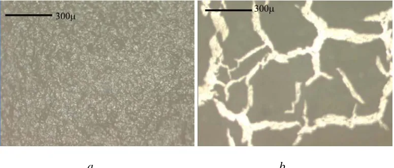
Figure 26:Optical microscope picture of the cross-section of a moul [49] ... 47
f ,
Figure 28: Photographs of gold sputtered electrodes [39] ... 48
Figure 29: Photographs of evaporation-deposited electrodes [39]... 49
Figure 30: Air gun... 55
Figure 31: a) Film with mask b) Final actuator... 56
Figure 32: Preparation of polymerizing pyrrole solution ... 57
Figure 33 Polypyrrole coated acrylic film... 59
Figure 34:Olympus BX 60... 60
Figure 35: Sony/Tektronik 370 Programmable Curve Tracer ... 61
Figure 36: Microscope platform with arm and plastic plate ... 62
Figure 37: Conductivity measurement spots for electrodes ... 63
Figure 38:Frame on the lab-jack ... 64
Figure 39: PPy actuator (connected to the voltage supplier with alligator clamps)... 65
Figure 40: Nusil CF19-2186 grease electrode a) 10% graphite b) 20% graphite ... 67
Figure 41: Nusil CF19-2186 rubber electrode a) 5% graphite b) 10% graphite c) 20% graphite... 68
Figure 42: Sylgard 184- Fluid 200® FL 50 CST grease electrode a) 5% graphite b) 10% graphite... 69
Figure 43: Sylgard 184- Fluid 200® FL 50 CST grease electrodes a) 5% graphite b) 6% graphite c) 7% graphite d) 8% graphite e) 9% graphite f) 10% graphite ... 70
Figure 44: Sylgard 184- Fluid 200® FL 50 CST rubber electrode a) 5% graphite b) 10% graphite c) 20% graphite... 71
Figure 45: Sylgard 186- Fluid 200® FL 50 CST grease electrode a) 5% graphite b) 10% graphite c) 20% graphite... 73
Figure 46: Sylgard 186- Fluid 200® FL 50 CST rubber electrode a) 5% graphite b) 10% graphite c) 20% graphite... 74
Figure 47: PPy electrode a) polymerized 3 times b) polymerized 5 times c) polymerized 10 times ... 75
Figure 48: Resistance values of 5, 10 and 20% Sylgard 184 rubber electrode as a function of distance between the probes... 77
Figure 49: Comparison of the resistance values of the 5, 10 and 20% Sylgard 184 rubber electrodes ... 78
Figure 50: Resistance values of 5, 10 and 20% Sylgard 186 rubber electrode as a function of distance between the probes... 79
Figure 51: Comparison of the resistance values of the 5, 10 and 20% Sylgard 186 rubber electrodes ... 79
Figure 52: Resistance values of 5 and 10% Sylgard 184 grease electrode as a function of distance between the probes... 80
Figure 53: Resistance values of , 5, 10 and 20% Sylgard 186 grease electrode as a function of distance between the probes... 81
Figure 54:Resistance values o PPy electrode with 3 different polymerizing layers (3 5 and 10 times as a function of probe distance... 82
Figure 57: Resistance values of Sylgard 184 10% rubber electrode under 0%-0% and 50%-50% nominal strain ... 85 Figure 58: Sylgard 184 10% rubber electrode a) under 0%-0% nominal strain b) under
100%-100%nominal strain... 86 Figure 59: Resistance values of Sylgard 184 10% rubber electrode under 0%-0% and
50%-50% nominal strain ... 87 Figure 60: Sylgard 186 10% rubber electrode a) under 0%-0% nominal strain b) under
100%-100%nominal strain... 87 Figure 61:Percolation experiments graph ... 89 Figure 62: Applied voltage-strain curve for Slygard 184- Fluid 200® FL 50 CST grease
electrodes ... 90 Figure 63: Applied voltage-strain curve for Sylgard 184- Fluid 200® FL 50 CST rubber
electrodes ... 91 Figure 64: Applied voltage-strain curve for Sylgard 186- Fluid 200® FL 50 CST grease
electrodes ... 92 Figure 65: Applied voltage-strain curve for Sylgard 186- Fluid 200® FL 50 CST 5% rubber
electrode ... 92 Figure 66: Applied voltage-strain curve for PPy electrodse... 93
1 Introduction
Natural muscles are considered as ideal actuators because of their high energy
density, fast speed of response, and large stroke length. All of these characteristics are
desirable in many applications. Research efforts are underway for a long time to develop
“artificial muscle actuators for robotic applications.
During the recent years, a new class of polymers is being investigated for their
response to electrical stimulation with a significant shape or size change. These polymers
have been described as Electro Active Polymers (EAPs). This potential of the EAPs is very
important for engineers and scientists from many different disciplines. The most important
characteristic is their similarity to biological muscles and their ability to induce large
displacements [1].
EAPs can be formulated to have a wide range of electronic and/or electro-optical
properties that can be tailored through the chemical composition and structure of the
polymers themselves. These properties can often be made to change in response to
external stimuli such as applied electric or magnetic field, light, pH and stress [2].
According to their actuation mechanism EAPs can be broadly divided into two
categories [3];
1. Ionic EAPs
2. Electric EAPs
The distinction between these two groups will be discussed further in sections 2.1.1
One of the subgroups of Electric EAPs is Dielectric (DE) EAPs. These materials are
also known as electrostatically stricted polymers (ESSP). Electrostatically stricted polymers
are the materials that contain a flexible backbone polymer and grafted crystalline groups
and offer high strain under an applied electric field. These polymers characterized by low
elastic stiffness and high dielectric constant can be used to induce large actuation strain by
subjecting them to an electrostatic field.
The working principle of Dielectric Elastomers (DE) is most easily understood when
comparing them to a capacitor. They consist of a thin film between two electrodes. The
actuation of dielectric EAPs is due to Maxwell Stress, discussed in further detail in section
2.2.1.1 [1].
The choice of materials and fabrication of the electrode for dielectric EAPs is an
ongoing area of research. Among the electrode properties that are relevant to actuator
performance is its ability to deform. If the electrodes cannot stretch in at least one planar
direction of the dielectric film, actuation will be dramatically reduced. Because of this,
compliant electrodes are the key feature of the Electro Active Artificial Muscle (EPAM)
technology. Compliant electrodes will be discussed in section 2.3 [4].
There are two limits of actuation for a dielectric actuator; these are dielectric failure
(breakdown) and loss of conductivity of the electrodes under strain. An ideal conformable
electrode should allow actuation up to dielectric failure of the dielectric actuator. Therefore,
in order to determine the compliant electrode performance evaluation of electrode
conductivity as a function of strain and also actuation strain of the dielectric actuator as a
2. Background
The observation of electroactive behavior of polymers can be traced back to an 1880
experiment conducted by Roentgen. Roentgen used a rubber band with fixed end and a
mass attached to the free end, and then he charged and discharged the rubber band.
Another scientists Sacerdote followed this experiment with a formulation of the strain
response to electric field activation in 1899. In 1925 scientists discovered the piezoelectric
polymer. A piezoelectric polymer is defined as a material that changes shape when a voltage
is applied to it, or releases a voltage when its shape is changed. There are many polymers
that display volume or shape change in response to perturbation of the balance between
repulsive intermolecular forces, which act to expand the polymer network and attractive
forces to act to shrink it. Generally, electrical excitation is only one type of stimulator that
can induce elastic deformation in polymers. Many polymeric materials can also be activated
using chemical, thermal pneumatic, optical and magnetic stimulant as well [1, 5, 6].
Polymers that are chemically stimulated were discovered more than half a century
ago when collagen filaments were demonstrated to reversibly contract or expand when
dipped in acidic or alkali aqueous solutions, respectively. After observation of piezoelectric
activity in poly (vinylidene fluoride), investigators started to examine other polymer systems,
and a series of effective materials have emerged. The largest progress in EAP materials
development has occurred in the last ten years where effective materials that can induce
2.1. Electroactive Polymers (EAPs)
As mentioned earlier, electroactive polymers are those that respond to electrical
stimulation with a significant chance in shape or size. The most important characteristic is
their similarity to biological muscles and their ability to induce large displacements [2, 4, 5,
7, 8].
Before EAPs, electroactive ceramics [EAC] and shape memory alloys [SMA] have
been the primary source of actuation materials for smart structures and actuation
mechanisms for many years. Application of these materials includes robotics, active
damping, vibration isolation, manipulation, articulation, and many others. On the other
hand, EAPs received relatively little attention due to the small number of available materials,
and their limited actuation capability [1, 5, 8].
During the last ten years many new and effective EAP materials have been identified
and improved fabrication techniques have emerged that have demonstrated potential
capabilities of these materials. Table 1 shows the comparison of some of the relevant
Table 1: Comparison of the properties of EAP, SMA and EAC [1]
As seen Table 1, EAPs can induce strains that are as high as two orders of
magnitude greater than the striction-limited, EACs. Also EAPs are superior to SMAs in higher
response speed, lower density, and grater resilience. So generally EAPs hold a great deal of
potential [1, 3, 10].
The EAPs are classified into two categories based on their mechanism of actuation,
ionic and electric [1];
2.1.1 Ionic EAPs
Polymers containing ions have been referred to as ionic polymers. An ionic polymer
is a material that contains a loosely collected arrangement of charged atoms (ions) bonded
Figure 1
:Ionic EAPs actuator operating principle [11]
In the early 1990s, it was demonstrated that applying a voltage across an ionic
polymer produces mechanical deformation. Conversely, application of mechanical
deformation produces charge flow. These materials show change in shape or dimension due
to migration of electrons in response to electric field [1, 2, 5, 11]. Thus, ionic materials can
be used as electromechanical sensors and actuators. The key to understanding this behavior
is related to the strength of the bonds between those negatively charged side groups and
the positively charged ions. When the material is hydrated, the bond between the positive
ions (cations) and the negative side group weakens while the side group maintains a strong
bond to the polymer backbone [11, 12, 13].
Figure 2: Ionic EAPs actuator operating principle [11]
On application of an electric field the weak bond between the cation and the side
group breaks, freeing the cation to “move” in the polymer. The side group remains fixed to
the backbone and doesn’t move. The motion of the cations also ‘drags’ water to the
negatively charged surface. The motion of water produces a pressure gradient in the
material. The result of the water motion is a pressure gradient through the thickness of the
polymer. The pressure gradient produces a bending moment of on the material, resulting in
mechanical strain and bending of the polymer [11].
Ionic EAPs can be classified into five groups according to their chemical properties [3];
1. Ionic Polymer Gels (IPG)
2. Ionomeric Polymer-Metal Composites (IPMC)
3. Conductive Polymers (CP)
4. Carbon Nanotubes (CNT)
2.1.1.1 Ionic Polymer Gels (IPG):
Polymer gels are multi-phase materials consisting of a cross-linked polymer network
and interstitial fluid. They are cross-linked polymers swollen in a solvent. The principle of
the gel’s motion is based on the molecular assembly reaction of cationic surfactant
molecules with negatively charged hydrogel caused by both electrostatic and hydrophobic
interactions to give the effective contraction. Generally, the swelling of ionic gel is attributed
to the difference of osmotic pressure concerned with the freely mobile ions between inside
and outside the gel. The contraction of the surfactant solution is connected with the
neutralization of negative charges in the gel by forming with cationic surfactant molecules.
Another factor affecting the volume of the gel is the interaction of the polymer and the
interstitial fluid. The affinity between the polymer and fluid enables the polymer network to
absorb the fluid and swell. The forces, which affect this interaction, work to increase the
volume of the gel. Many different polymer gels have been developed which react to various
kinds of environmental change such as pH change and the application of an electric field
[14, 15].
Ionic polymer gels have the potential of matching the energy density and the force
of biological muscles. One of the examples for these gels is polyacrylonitrile (PAC). The
polyacrylonitrile materials are activated by chemical reaction(s), a change from an acid to an
alkaline environment inducing an actuation through the gel becoming dense or swollen.
Because of the diffusion of ions through the multilayered gel, the actuation of these
-2.1.1.2 Ion-exchange Polymer Metallic Composites (IPMC)
A typical IPMC consists of a thin polymer membrane with metal electrodes plated on
the both faces. IPMCs respond to an electrical activation as a result of the mobility of
cations in the polymer network. The stimulation of an IPMC in the hydrated state results in
a fast bending deformation. Both the fixed anions and the mobile counter-ions are subjected
to an electric field because of the external stimulation and counter-ions become able to
diffuse toward one of the electrodes. As a result, the composite undergoes a bending
deformation toward the anode, followed by a slow relaxation in the opposite direction [1,
18, 19].
Generally, two types of base polymers are employed to form IPMCs these are
Nafion® (perfluorosulphonate manufactured by Du Pont) and Flemion® (perfluorocaboxylate
manufactured by Asahi Glass, Japan). IPMC require relatively low voltages to stimulate a
bending response (1-10 V) with low frequencies below 1 Hz [16, 20].
2.1.1.3 Conductive Polymers (CP)
CPs are a class of materials that feature a conjugated backbone structure. These
polymers exhibit chemically and electrochemically controllable electronic conductivities. CPs
response to an electrical activation via the reversible counter-ion insertion and expulsion,
that occurs during redox cycling. Significant volume changes occur through oxidation and
reduction reactions at corresponding electrodes through exchanges of ions with an
electrolyte [17, 21, 22].
Polypyrrole (PPy) and polyaniline are the two common conductive polymers that
belong to this class. CP actuators require voltages in the range of 1-5 V. Variations to the
2.1.1.4 Carbon Nanotubes (CNT)
Carbon nanotubes are unique nanostructures. They have remarkable electronic and
mechanical properties. Researchers have first focused on their exotic electronic properties,
since nanotubes can be considered as prototypes for a one-dimensional quantum wire [25].
An ideal nanotube can be thought of as a hexagonal network of carbon atoms that
has been rolled up to make a seamless cylinder. Just a nanometer across, the cylinder can
be tens of microns long, and each end is "capped" with half of a fullerene molecule.
Single-wall nanotubes can be thought of as the fundamental cylindrical structure, and these form
the building blocks of both multi-wall nanotubes and the ordered arrays of single-wall
nanotubes called ropes [25, 26].
The actuation mechanism of CNTs is through an electrolyte medium and the change
in bond length via the injection of charges that affect the ionic charge balance between the
nano-tube and the electrolyte. If more charges are injected into the CNT the dimension
change be larger [17].
As a consequence of the mechanical strength and modulus of single CNTs and the
achievable actuator displacements, these EAPs can boast the highest work per cycle and
generate much higher mechanical stresses than other forms of EAPs [17, 27].
2.1.1.5 ElectroRheological Fluids (ERF)
ERFs are electroactive fluids that change their rheological properties, in the presence
of an electric field. These fluids are made from suspensions of an insulating base fluid and
ERFs rapidly solidify or increase their viscosity dramatically, in response to an electric
field due to the formation of particle chains that bridge the electrodes. These materials are
made by suspending particles in a liquid whose dielectric constant or conductivity is
mismatched in order to create dipolar particle interactions in the presence of an AC or a DC
electric field [29].
2.1.2 Electric EAPs
Electric EAPs are the polymers that can be driven or activated by an electric field or
Coulomb forces. The electronic polymers (electrostrictive, electrostatic, piezoelectric, and
ferroelectric) can be made to hold the induced displacement under activation of a DC
voltage, allowing them to be considered for robotic applications. Except for CP, ionic EAPs
don’t hold strain under DC voltage. Also, electric EAPs have a greater mechanical energy
density (see Figure 3) and they can be operated in air with no major constraints [1, 5, 17].
Electric EAPs are very attractive in terms of energy conversion. This class of EAPs
converts electric energy to mechanical energy and hence can be utilized as both solid-state
electromechanical actuators and motion sensors. The electromechanical response in this
class of polymers can be linear such as piezoelectric polymers or electrects or nonlinear
such as the eleoctrostrictive polymers and Maxwell stress effect induced response. Electric
EAPs can require large electric fields (>100-V/mm), to achieve longitudinal deformations at
the range from 4-350% [13].
Electric EAPs can be classified into six groups according to their response to the applied electric field [3];
1. Ferroelectric Polymers
2. Dielectric Elastomers
3. Electrostrictive Graft Elastomers
4. Electrostrictive Paper
5. Electro-Viscoelastic Elastomers
6. Liquid Crystal Elastomer (LCE) Materials
2.1.2.1 Ferroelectric Polymers
A ferroelectric polymer can be defined as a polymer in which the application of an
electric field reverses the direction of spontaneous polarization. These kinds of polymers can
be in a single crystal form or a semi-crystalline form in which the ferroelectric crystallites are
embedded in an amorphous matrix. These polymers can be formed into thin flexible sheets
Poly (vinylidene difluoride) (PVDF) and its copolymers are the most promising
materials of this class. Especially by electron irradiation treatment, very high strain and high
energy density properties can be gained to these materials. Electric induced strain response
in the copolymer is mainly from the electric field induced phase transition between nonpolar
to polar phases in the crystalline area [29, 31, 32, 33].
Ferroelectric polymers have attracted a great deal of attention due to their many
desirable properties, such as flexibility, light weight, high mechanical strength, ease of
processability to large area films and ability to be molded into a desirable configuration.
However they have some disadvantages. Most ferroelectric polymers have the
disadvantages of low electric field sensitivity in terms of their dielectric constant,
piezoelectric coefficient, electromechanical coupling coefficient, and field induced strain.
These disadvantages limit their applications. PVDF and its copolymers are the most
promising materials of this class [29, 34].
2.1.2.2 Dielectric Elastomer EAPs
Dielectric elastomer EAPs are rubbery polymer materials that have a large
electromechanical response to an applied electric field. Electrostatic fields can be applied to
those polymers exhibiting low elastic stiffness and high dielectric constants to induce large
actuation strain, these polymers are known as electro-statically stricted. Electrostriction is
the property of the dielectrics that manifests as relatively slight change of shape or
mechanical deformation under the application of an electric field. The actuation mechanism
of dielectric EAPS is due to Maxwell stress. Dielectric EAP actuators require large electric
2.1.2.3 Electrostrictive Graft Elastomers
A grafted elasomer is a material, which has a flexible polymer backbone and grafted
crystalline groups. The grafted crystalline phase provides the polarizable moieties for the
electric field response and serves as cross-linking sites for the elastomeric system. These
elastomers offer large electric field induced strain [1, 37, 38].
In 1998, a graft elastomer EAP was developed at NASA Langley Research Center
that exhibits a large electric field induced strain. The material exhibits high electric field
induced strain (~4%) combined with mechanical power and excellent processability [34,
38].
2.1.2.4 Electrostrictive Paper
Electrostrictive papers produce large displacement with small force under an
electrical excitation. Electrostrictive paper is a sheet that is composed of a multitude of
discrete particles, mainly of a fibrous nature, which form a randomly organized network
structure. These are produced in various mechanical processes with chemical additives.
Because of this, it is possible to prepare a paper that has electroactive properties. The
operational principle of electrostrictive paper is due to electrostriction effect associated with
a combination of the electrostatic force of electrodes and the intermolecular interaction of
the adhesives [39, 40, 41].
Kim et al investigated an electrostrictive paper actuator that has been prepared by
bonding two silver laminated papers with silver electrodes placed on the outside surface.
When an electric voltage is applied to the electrodes the actuator produces bending
displacement, and its performance depends on the excitation voltages, frequencies, type of
These types of actuators are lightweight, simple to fabricate and are likely to be
used in applications such as active sound absorbers, flexible speakers and “smart” shape
control devices [1].
2.1.2.5 Electro-Viscoelastic Elastomers
Electro-viscoelastic materials are characterized as having stiffness and damping
properties that vary with frequency, temperature and applied voltage. These materials are
composites of silicone elastomers. After curing an electric field is applied that orientates the
polar phase within the elastomeric matrix. An applied electric field (<6 V/µm) induces changes in shear modulus. Typical potential applications are as alternatives to
electro-rheological fluids for active damping applications [29, 23].
2.1.2.6 Liquid Crystal Elastomer (LCE) Materials
These materials posses EAP characteristics by inducing Joule heating. LCEs are
composite materials consisting of monodomain nematic liquid crystal elastomers and
conductive polymers, which are distributed within their network structure. The actuation
mechanism is a phase transition between nematic and isotropic phases. The actuation takes
place in less than a second [42, 43]
2.2 Dielectric Elastomer EAPs
Polymers with low elastic modulus and high dielectric constant have been used to
induce large actuation strain by subjecting the material to an electrostatic field. Dielectric
2.2.1 Actuation Mechanism of DE EAPs
It has been well known that the electric field pressure from free charges on the
surface of all insulating materials induces stresses that strain the material. This stress is
called Maxwell stress. A dielectric elastomer actuator can be considered as a compliant
capacitor where the polymer is sandwiched between two compliant electrodes. When a
capacitor is charged, a pressure arises between the two electrodes. This pressure, known as
the Maxwell pressure (p), arises from the fact that the plus-charges on one electrode attract
the minus-charges on the other, and the electrostatic forces resulting from the free charges
squeeze and stretch the polymer. So dielectric elastomer technology function on the simple
principle that, when a voltage is applied across the electrodes, the polymer shrinks in
thickness direction and expands in its plane. These changes reduce the electrical energy and
the difference is converted to mechanical work [1, 2, 4, 8, 9, 35, 36, 45, 46 ].
2.2.1.1 Maxwell Pressure
As mentioned above, free charges, which are placed, on the surface of the insulating
materials induces stresses when subjected to an electric field. These stresses strain the
material and called Maxwell pressure. Maxwell pressure can produce powerful electroactive
responses in certain elastomers [8, 46, 47, 48, 49, 50].
Maxwell pressure is created when a capacitor is charged. Electrostatic forces
resulting from the free charges squeeze and stretch the polymer and as a result, the
dielectric polymer as well as the electrodes expands in area. Stretching separates like
charges and hence reduces electrical energy and also decreases the film thickness. The
reduction in electrical energy is balanced by an increase in elastic mechanical energy and/or
to each other and in the process converts electrical energy to mechanical energy. For the
compliant medium Maxwell pressure is expressed as;
2 0 2
0
E
(
V
z
)
p
=
εε
=
εε
where E is the electric field, ε is the dielectric constant, ε0 is the permittivity of free space, V
is the applied voltage and z is the polymer thickness [1, 4, 9, 45, 48]. Figure 4 shows the
operation principle of dielectric polymer actuator.
V
Polymer film
Voltage on
Compliant electrodes (on top and bottom surfaces)
Figure 4: Dielectric polymer actuator operating
2.2.1.2 Dielectric Elastomers
As mentioned before dielectric elastomers are rubbery polymer materials that have
a large electromechanical response to an applied electric field. These materials are also
dielectric elastomer as an actuator are specific energy density, actuation pressure and
strain, response time and efficiency. We can also add low viscoelastic losses, a wide range
of temperature and humidity tolerance and ease of fabricating thin films to these properties
[1, 4, 8, 17, 29, 35, 36]
We can characterize DE materials according to their two important mechanical
properties. One is their ability to undergo large elastic strain and the other one is their
ability to maintain volume during their deformation. Compared to many other electroactive
materials such as piezoelectric ceramics and magnetostrictive ceramics, dielectric elastomers
are relatively compliant, capable of extremely large strains and have high energy densities.
These materials also have fast response time and high electromechanical efficiency. The
technology is probably the most attractive polymer based actuator technology for robotic
applications [44, 49].
Several dielectric elastomer polymers have shown good performance as an actuator.
Silicones (based on poly(dimethyl siloxane)) and a commercial acrylic (available from 3M
Corp.) have shown the greatest strain and total energy density. Maximum strains of more
than 100% have been shown with both of these materials. The data in Table 2 identify the
Table 2:Maximum response of representative elastomers [4]
Kofod and his coworkers at SRI international [44], focused on understanding the
basic physical mechanism underlying the observed electromechanical response of
polyacrylate dielectric elastomers. They also considered factors affecting the dielectric
strength of the material, since the maximum performance of an actuator will depend on the
maximum electric field that can be applied to the material.
They used 3M 4910 VHBTM acrylic adhesive tape with carbon grease electrodes (from
Circuit WorksTM) in order to carry out their experiments. VHB 4910 is a very high bond
structural adhesive from 3M. These tapes are available as a 1mm thick sheet, mounted on a
red plastic liner, which makes it very easy to cut to preferred dimension. Due to its
stickiness it is veryeasy to stretch and mount on frames, making it a very good material for
testing demonstration devices. The film is translucent and extremely compliant and can be
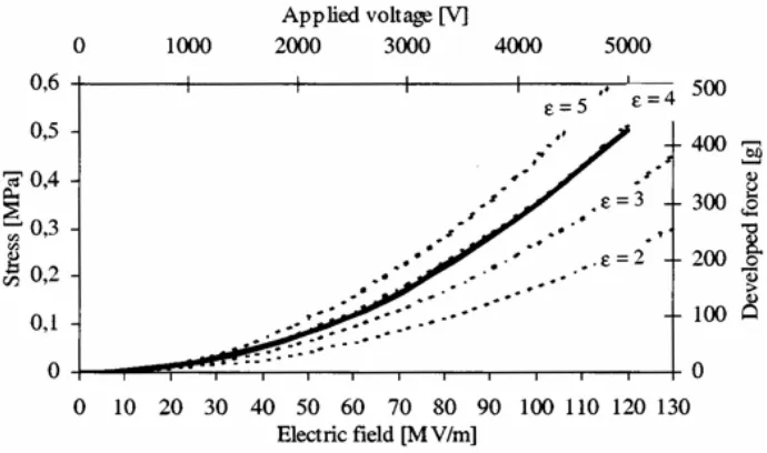
Kofod et al [44] reported evaluation of stress/force as a function of electric field
strength for VHB 4910dielectric elastomer at different levels of pre-strains. The geometry of
the set up that Kofod et. al. set for measuring the field induced stress is shown in Figure 5.
The film was pre-strained 500% in the x direction and was glued to the plastic beams as
shown in Figure 5. One of the beams was fixed to a translation table and the other was
attached to a load cell. Conductive grease electrode was smeared on both sides of the film.
Three different pre-strain levels in the y direction, 300%, 400% and 500% were used. The
pre-strain in the y direction was controlled by a micrometer-screw. The load cell was zeroed
at the specified pre-strain levels. On application of voltage (upto 5 kV), the recorded
force-voltage curves were parabolic with an apparent relative dielectric constant of approximately
4. As shown at Figure6, the dotted lines are the expected parabolic curves corresponding to
the relative dielectric constant written next to the curve. The experimental curve followed a
parabolic behavior with an apparent relative dielectric constant 4. Figure 6 shows the
stress/force vs electric field/voltage curve for sample with 500% x 300% pre-strain [44].
Dielectric elastomer with electrodes on both surfaces
Plastic beams
Force gauge
String
X direction
Figure 5: Experiment set-up the x and y directions are horizontal and vertical, respectiveley
Figure 6: Stress/force vs electric field/voltage curve for sample with 500% x 300% pre-strain
[44]
The dielectric constant of the unstrained material is 4.7 according to the 3M
literature. The difference was 18%. The 18% lower performance of the actuator was
explained by deviations between the test set up (Figure 5) and ideal conditions. They also
found that there is a slight tendency for the higher pre-strain curves to produce slightly less
force in response to the applied voltage as shown in Figure 7 [44].
Figure 7: Force/voltage curve for the same sample at different strains in the length direction
[44]
Kofod et al. also observed that the electric field that may cause breakdown of the DE
depended on the pre-strain ratio. In the unstrained state the breakdown field was 20MV/m,
when the film was pre-strained 500% x 500% the breakdown field was reported 218MV/m.
Kofod et. al. concluded that the breakdown strength across a polymer chain is higher than
along it. The orientation of the polymer chains in the plane of the film due to the pre-strain
increases the breakdown strength. Figure 8 shows the relation between the thickness,
breakdown electric field and the breakdown voltage [44].
Figure 8: Electrical breakdown strength of isotropically pre-strained acrylic tape [44]
Pelrine and coworkers [50] carried out experiments in order to determine the
response of dielectric materials to the applied voltage. They evaluated various silicone films
(Nusil Technology’s CF19-2186, Dow Corning HS3) as well as one acrylic foam tape (3M’s
VHB 4910) mentioned earlier. Perline et al [50] reported extraordinarily high levels of
actuation strians of 215% for acrylic tape; five to six times those previously reported earlier.
They also reported higher pressures (up to 7 MPa) and energy densities about 23 times of
those reported earlier for acrylic tape. They attributed the observations to the unique
characteristics of VHB 4910 acrylic foam tape, as well as the application of high pre-strain in
one planar direction, which enhances electrical breakdown strength and causes the material
to actuate primarily in the low pre-strain planar direction.
Linear strain and areal strains measured by Perline et al for the three elastomers
under different conditions of pre-strain are given in Table 3. Actuated strains of silicones
acrylic foam tape. Silicone elastomers also have other desirable material properties such as
good actuation pressures and high theoretical efficiencies (80 to 90%) because of the
elastomers’ low viscoelastic losses and low electrical leakage. The VHB 4910 acrylic
elastomer produced highest performance in terms of strain and actuation pressure. Perline
et. al. also reported that acrylic films were operated continuously for several hours at the
100% relative area strain level with no apparent degradation in performance. However, it
was observed that acrylic elastomer had relatively high viscoelastic losses that limited its
half-strain bandwith to about 30 to 40 Hz in the areal strain test [50].
Table 3: Circular and linear test results for different types of elastomers [50]
In another publication, Pelrine and his coworkers [9] compared natural muscles with
various man-made actuators, see Table 4. In order to achieve the important characteristics
strain, speed of response, efficiency, and controllability. They mentioned that electroactive
polymer technologies based on electric field induced deformation of dielectric polymers with
compliant electrodes is a promising area because of their high strains and energy densities.
Table 4: Comparison of natural muscle and man made actuator technologies [9]
According to Pelrine et al [9], it is important that an actuator be able to deliver
muscle-like performance at common muscle frequencies. They tested various characteristics
of natural muscle such as stress, strain and power density at various frequencies and
compared it with acrylic elastomer. They found that the acrylic DE actuator fell within the
general trend of muscle like performance. Figure 9 shows the strain and stress of DE
Figure 9: Strain and stress of DE actuator compared to various natural data points [9]
Perline et al [9] also compared power density and work-per cycle performance of
natural muscle and acrylic DE actuators. They found that the measured performance of the
relevant parameter falls within the general trend of natural muscle. Figure 10 shows the
Figure 10: Power density and work-per cycle for DE actuator compared to natural muscle
data points [9]
Meijer et al [51] studied the performance of different actuators based on EAP
technology and compared them with the human muscle. Two of the DE they tested were
3M’s VHB 4910 acrylic tape and NuSil Technology’s CF 19-2186 silicone material. Both of the
films were coated with carbon grease (CW 7200 of Chemtronics Circuit works) compliant
electrodes. Figure 11 and 12 shows the actuator design and the experimental set up
respectively. Acrylic film and silicone film were glued to a wooden support system (see
Figure12) at a 1.5 N pre-tension and 1 N pre-tension respectively. The experimental set up
they used consisted of a muscle lever system that can simultaneously record position and
force. One side of the EAP actuator was connected to the muscle lever and the other side
Figure 11: Schematic design of the actuators [51]
Figure 12: Picture of the acrylic dielectric elastomer actuator. The black arrow indicates the
length changes that were imposed on the actuator by the muscle lever. [51]
The EAP material was activated using an electrical circuit that generated square
wave high voltage (0-5kV) pulses of varying duration (10-500 ms). A personal computer
controlled the timing of the stimulation to the EAP actuator.
In order to characterize the mechanical performance of the actuators, Meijer et al
when they performed work on the environment. Isometric force was defined as the maximal
change (increase or decrease) in force that could be attained with an applied stimulus.
Isometric stress was calculated by normalizing the force to the area perpendicular to the
force direction. They concluded that maximal isometric stress of the dielectric elastomers in
the stretch direction were all within the range found for biological muscle. Figure 13 shows
the graphs for acrylic elastomer and silicone elastomer [51]
Figure 13: Maximal isometric contractions of the tested actuators [51]
In addition Meijer et al [51] evaluated the generation of work and power in the
actuators. First they evaluated the passive work-loops of the actuators when they were not
Figure 14: Passive workloops of the tested actuators at an oscillatory frequency of 2Hz [51]
In order to have the DEs generate positive work, the actuators needed to be
stimulated during the lengthening phase of the workloop. This resulted in a small force
during lengthening and a larger force during shortening and hence the generation of work.
Figure 15 shows the active workloops that maximized work output. Meijer et al found that
maximum work output was attained at a strain of 5%. Despite the large visco-elastic losses
the acrylic actuator still generated large work outputs. Table 5 shows the comparison of two
Figure 15: Active workloops of the tested actuators at an oscillatory frequency of 2Hz [51]
Table 5:
Comparison of natural muscle and man made actuator technologies
[51]
2.3 Compliant Electrodes
As mentioned before dielectric elastomer actuators consist of a thin film between
two electrodes. One of the main characteristics of dielectric elastomer actuators, maybe the
actuation the electrodes around the DE should also deform without imposing any restraints
while maintaining their conductivity. In other words the electrodes have to be compatible
with the DE in their mechanical properties. Therefore the compliant electrode is a key
feature of the DE actuator technology.
In addition to mechanical properties such as elastic moduli, hysterisis, etc., other
properties such as conductivity, percolation, are also of importance. Compliant electrodes
should conform to the shape of the DE they are attached to. The electrodes must stretch in
at least one planar direction of the film while its thickness contracts; otherwise actuation will
be dramatically reduced. The electrode system should follow the strain of the actuator
system without generating opposing force, while maintaining its conductivity during the
actuation. In summary the mechanical behavior of the desirable compliant electrodes are
critical for the performance of the actuator must be compatible with the dielectric polymer
behavior, in that these must accommodate large deformation without substantial loss of
conductivity under repeated deformation cycles. Compliant electrodes should be thin and
should be easily patternable as well [52, 53].
Many types of compliant electrodes used in conjunction with DE actuators have been
reported in the literature. Among them are particle included polymers, metals, and
conductive polymers. Particle included polymer based electrodes generally consist of carbon
or silver as particles and a polymer medium such as silicone. Traditionally, these have been
classified as grease and rubber electrodes [4, 39, 49, 52, 53].
2.3.1 Grease and Rubber Electrodes
The distinction between grease and rubber electrode type is their preparation
Grease electrodes consist of a carrier polymer and powdered graphite particles. To
prepare grease electrodes, a suspension of graphite in a solvent (for the polymer media),
prepared using ultrasound is added to polymer carrier (in compatible solvent). Ketjenblack®
EC-300J (produced by Akzo Nobel) can be used as graphite and silicone materials can be
used as polymer carrier. Both for polymer carrier and graphite, heptane can be used as
solvent. Than mixture is placed in a fume hood to allow the solvent to evaporate. The
evaporation process is interrupted at the optimum application viscosity level. Grease
electrodes can be applied on the film with a brush [52, 53].
Rubber electrodes also consist of a carrier polymer and powdered graphite as
conductive particles like grease electrodes. Once again, a suspension of graphite in solvent
(for the carrier polymer), prepared using ultrasound is added to polymer carrier. The
component materials described earlier for grease electrodes can also be used for rubber
electrodes. The low viscosity mixture can then be sprayed with an airbrush on dielectric
films to form rubber electrodes [52, 53].
Toth and Goldenberg [54] characterized the variation in impedance of various
electrodes as a function of stretch. A schematic diagram of their experimental set up is
shown in Figure16. The electroded film was stretched in increments of 25% and the
impedance was measured between the reference node and each of the measurement points
at each state of stretch. Figure 17 shows the measured resistance for a carbon grease
Figure 16:
Schematic diagram for the testing of the electrode resistance [54]
General Electric), for silver conducting grease (CW 7300
from Chemtronics), and graphite powder (S4). They expressed their empirical observation of
strain-resistance relationship as;
Toth and Goldenberg [54] also found similar relationships for other electrode
materials which were carbon conductive grease (CW 7100 from Chemtronics), conducting
RTV silicone (RTV 60-CON from
log
R
=
b
(
α
− +
1)
c
where b and c are experimentally determined constants and
α
is the stretch ratio. Theywrote this equation as
and re
( 1) 0
( )
R
=
R
β
α−R
i
0
R
β
=
is no stretch on
the DE
where R0 and Ri are the resistance measured at α equal to 1 and α equal to 2
respectively. Sinceαrepresents the stretch ratio, when α is equal to 1, there
film. When α is equal to 2, there is 100% stretch on the DE film. If
β
is high, itmeans the electrodes loose their conductivity when the film is stretched.
Toth and Goldenberg [54] calculated values of β for some common electrode
materia
.
Faldt and Kofod [53] investigated dielectric spectroscopy of graphite filled silicone ls: 4 for carbon conductive grease (CW 7100), 6.5 for conducting RTV silicone (RTV
60-CON), 6.8 for silver conducting grease (CW 7300), and 22 for graphite powder (S4) [54]
ording to the
graphite percentage by volume. For low graphite content, the graphs have a constant slope
of ~ 1. For percentages higher than 23%, the graphs have a constant plateau at low
frequencies, but at higher frequencies they return to a slope of ~ 1 [53].
content. The samples were prepared as a mixture between graphite powder (4206 Merck,
Germany) and Dow Corning Sylgard 184. Samples were cast from a heptane solution
directly on to glass plates. Samples of thickness ranging from 500 µm to 1000 µm were prepared with graphite content in percentages from zero to 30% in steps of 1%. Faldt and
Kofod [53] found that the conductivity changes significantly between the samples with 23%
and 24% graphite. Figure 18 shows the results of percolation experiments acc
Figure 18: Percolation experiment graphs for Sylgard 184 with different percentages [53]
Kofod [53] evaluated two types of compliant electrodes, identified as rubber and
aterials as polymer carrier in order to prepare grease and grease. In his experiments, he used Ketjenblack EC-300J as graphite (produced by Akzo
n (by smearing on the film), mixture
contain
on 3M’s VHB 4910 acrylic tape and
different types of silicone films. Dow Corning Sylgard 184 and 186, Wacker Elastosil were
some o
ely new class of electronic materials that
may be
rubber electrodes. The difference between these two electrode types were their preparation
and application techniques.
For grease electrodes Kofod [53] used silicone (Sylgard 184) and viscosity lowering
agent Dow Corning 200FL 50 cst mixtures. Kofod prepared the electrode mixtures with the
graphite volume percentages of 3%, 5%, 10% and 20%. Kofod reported relatively high
resistance values for 3% graphite content, mixture containing 5%, 10% and 20% graphite
were all conductive. In terms of ease of applicatio
ing 5% graphite showed the best results followed by the 10% mixture. The mixture
containing 20% graphite was difficult to apply on the DEfilm. In case of rubber electrodes
Kofod tested several types of silicone with Wacker E43 RTV-1 silicone glue. In case of
rubber Kofod used only 20% graphite contetnt [53].
As for dielectric material, Kofod [53] worked
f them. Kofod used rubber and grease electrodes only for silicone films, not for VHB
4910 acrylic tape. He claimed that, since silicone sticks to silicone, rubber and grease
electrodes were suitable only for silicone films [53].
2.3.2 Conductive Polymer Electrodes
Electrically conducting polymers are a relativconsidered as potential candidates for the required electrodes. These polymers have
the potential of combining the electrical properties of metals with the processing advantages
of conventional polymers. Some of the examples of conductive polymers are polypyrroles,
pants such as sodium salt of antraquinone-2-sulfonic acid or
5-sulfosa
matera
ieve high
und that the interface
betwee
Cheng Z. Y et al [55], Su J. et al [56], Kuhn et al [57], Watanabe M. et al [58]
reported that polypyrrole is a conductive polymer and can be used as compliant electrodes
for the dielectric elastomer actuator systems. Details of their findings will be discussed later.
Polypyrole can be easily polymerized by using ferric chloride (FeCl3) in aqueous medium in
the presence of do
licylic dihydrate. By using in-situ deposition technique it is possible to form a
conductive polymer coating on the dielectric elastomeric films [55, 56, 57, 58] . When a
dielectric polymer film come in contact with an aqueous solution of an oxidatively
polymerizable pyrrole compound, oxidizing agent react with the pyrrole compound and from
a conductive polymer coating on the dielectric material. Polypyrrole electrodes will be
discussed later
Kuhn [56] published a patent about the depositon of polypyrrole to the textile
ls. Polypyrrole electrodes can be deposited on to the dielectric material by chemical
oxidation of pyrrole in an aqueous solution, which is called in-situ deposition technique. The
object of the invention was to provide a conductive textile material by depositing pyrrole to
the surface of the material. Patent recommends anthraquinone-2-sulfonic acid as doping
agent and also they claimed that a large excess of dopant is not required to ach
conductivity. Another advantage of the invention is the coating has superior stability [56].
Ji Su et al [57] used in-situ deposition technique, which was described at section
2.3.2, to form polypyrrole electrodes on polyurethane films. They evaluated polypyrrole
electrodes and compared them with gold electrodes. Ji Su et al fo
n polyurethane and polypyrrole electrodes is coherent and that the PPy electrodes
lm was measured
while the electrode was elongated using the frame. Watanabe et al reported that the
wrinkles enabled the electrode to elongate without decrease in conductivity. Figure 20
shows the resistance of the PPy electrodes under different conditions. According to the test
results, Watanabe et al reported that in the electrode prepared on the undrawn
polyurethane film, the resistance exponentially increased with the elongation, see Figure 20
a. In the electrode prepared on the 35.3%-drawn polyurethane film, the resistance was
almost constant at elongation rates less than 40%, see Figure 20 e [58].
polyurethane films. On the dielectric properties, they reported similar behavior for gold and
PPy electrodes. In addition, they found that under identical measurement conditions, the
large electric field induced strain responses and the characteristics of the thickness and
frequency dependence properties of both were similar as well [57].
Watanabe et al [58] reported on formation of wrinkled polypyrrole electrodes on
polyurethane films. The premise for the geometry was two-fold; first conductivity of the
electrode would not decrease with the field-induced surface extension of the actuator and
the second was that the electrode would not constrain the actuation. They prepared the
wrinkled polypyrrole electrodes through in situ deposition technique (as used by Ji Su et al
[57]). Watanabe et al prepared the wrinkled electrode on uniaxially strained (0-35.3%)
polyurethane films as shown in Figure 19. The strained film was then placed in a reaction
mixture of pyrrole to coat the film with the PPy electrode. After the reaction, the strain was
released, which made the electrode wrinkle because PPy is much less elastic than the
Figure 20: Resistance of the PPy electrode under elongation. The electrodes were prepared
rawn, c) 17.9% drawn, d) 28.2% drawn, e) 35.3% drawn PUE films
Watanabe et al [58] also reported that the wrinkled PPy electrodes improved the
ending-electrostrictive actuation of the polyurethane film. In order to evaluate the
ifference between the wrinkled PPy electrodes and unwrinkled PPy electrodes Watanabe et
a) undrawn, b) 9.8% d
[58]
b
al first prepared three samples (sample A, B and C) that had (unwrinkled) electrodes of
different thickness. To vary the thickness, Watanabe et al repeated the deposition of PPy
twice in Sample B and three times in Sample C. In Sample A, it was carried out only once.
The thickness ratio of the electrode was supposed to be Samples A:B:C=1:2:3. Watanabe et
al reported that the field induced displacement of Sample A was much larger than that of
means that the PPy electrode could constrain the bending actuation of the
nstrain the actuation because it could apparently elongate by smoothing the
wrinkles. Watanabe et al reported that the displacement of the film with the wrinkled
electrode was more than twice that of the film with the unwrinkled one, see Figure 22.
Sample C, which
polyurethane film, see Figure 21. Watanabe et al thought that the wrinkled PPy electrode
did not co
Figure 22: Field induced displacement of the PUE films with a) the wrinkled PPy electrode
and b) the unwrinkled one. The wrinkled electrode was prepared on the 10.5% drawn PUE
film [58]
It is important to note that they also found improved actuation with doping of the
polyurethane with sodium acetate. Figure 23 shows the field-induced bending of the film.
Watanabe et al reported that the wrinkled PPy electrode significantly improved the
ared with the unwrinkled one, see Figure 23 a and b. By comparing
and 23, the doping also improved the displacement [58]. displacement as comp
Figure 23: Field induced displacement of a) the doped PUE film with the wrinkled PPy
electrode prepared on the 9.9% drawn PUE film, b) the doped PUE film with the unwrinkled
PPy electrode and c) an undoped PUE film with a conventional gold electrode [58]
2.3.3 Metal Electrodes
Metals such as gold, silver and aluminums have been used to fabricate compliant
electrodes [4, 39, 49, 54]. These classes of compliant electrodes have high acoustic
impedance and impose mechanical constraints on the soft polymer DE that can significantly
reduce the electromechanical efficiency of the actuator. Metal electrodes have been
deposited by evaporative or sputtering processes. Generally, because of their high stiffness,
nbluh and co-workers [4] reported, sputter-deposited ultrathin gold electrodes
with thickness below 0.1mm. They reported that uniform gold electrodes easily crack and
strains greater than about 4% are difficult to achieve. As a remedy, they used patterned
electrodes rather than uniform gold electrodes and claimed that this structure could remain
conductive at much greater film strains. In their experiment, Kornbluh et al [4] used zigzag
patterns of sputtered gold traces uniformly on silicone films and then patterned via
photolithography, and gold traces were fabricated with line widths as small as 5µm, see Figures 24 and 25. They found that these electrodes remain highly conductive at film strains
up to 80%. Kornbluh et al [4] also mentioned that a second electrode material is needed to
carry the charges in between the zig-zag traces, for uniform distribution over the surface of
the polymer. The second electrode material can be any weakly conductive but soft
material. It can be a polymer filled with conductive particles such as fine carbon or it can be
an ionically or electronically conductive polymer [4].
Kor
![Table 2:Maximum response of representative elastomers [4]](https://thumb-us.123doks.com/thumbv2/123dok_us/1635395.1204069/32.612.153.492.111.356/table-maximum-response-of-representative-elastomers.webp)
![Table 4: Comparison of natural muscle and man made actuator technologies [9]](https://thumb-us.123doks.com/thumbv2/123dok_us/1635395.1204069/38.612.95.517.219.440/table-comparison-natural-muscle-man-actuator-technologies.webp)

![Figure 18: Percolation experiment graphs for Sylgard 184 with different percentages [53]](https://thumb-us.123doks.com/thumbv2/123dok_us/1635395.1204069/49.612.122.465.321.527/figure-percolation-experiment-graphs-sylgard-different-percentages.webp)
![Figure 20: Resistance of the PPy electrode under elongation. The electrodes were prepared a) undrawn, b) 9.8% drawn, c) 17.9% drawn, d) 28.2% drawn, e) 35.3% drawn PUE films [58]](https://thumb-us.123doks.com/thumbv2/123dok_us/1635395.1204069/54.612.94.527.71.498/figure-resistance-electrode-elongation-electrodes-prepared-undrawn-drawn.webp)
![Figure 23: Field induced displacement of a) the doped PUE film with the wrinkled PPy electrode prepared on the 9.9% drawn PUE film, b) the doped PUE film with the unwrinkled PPy electrode and c) an undoped PUE film with a conventional gold electrode [58]](https://thumb-us.123doks.com/thumbv2/123dok_us/1635395.1204069/57.612.198.352.114.394/displacement-wrinkled-electrode-prepared-unwrinkled-electrode-conventional-electrode.webp)