Algorithm in Automated Press Fit for
Rotor-Shaft Assembly of an Induction Motor
Mitesh. S. Agrawal1, Ankit. M. Rathi2, Prof. Prashant. B. Shiwalkar3
B.E Student, Department of Mechanical Engineering, Shri Ramdeobaba College of Engineering and Management,
Nagpur, India. 1,2
Associate Professor, Department of Mechanical Engineering, Shri Ramdeobaba College of Engineering and
Management, Nagpur, India.3
ABSTRACT: To survive in today’s vast competition and fast changing market, all organizations need the effective use
of updated technology and proper study of options available. This report is about a study of existing and proposed assembly procedure of Rotor –Shaft assembly during manufacturing of induction motors. The fitment is analyzed against available theoretical background. The experiments carried out provide relationship between the press-in-force and available interference between the mating parts and role of tolerance on shaft diameters. The algorithm developed provides a methodology to arrive at expected value of pressure gauge readings during assembly on the described hydraulic press. To ascertain customer specified ‘Torque capacity’ of the joint required, add-on control system for the assembly station is proposed.
KEYWORDS: Interference fit algorithm, Induction motors, Rotor-shaft assembly, Automated press fit.
I.INTRODUCTION
Press fitting joints are widely used in mechanical engineering to transmit a torque through the joint of two parts because of their high efficiency and easy implementation. Therefore, an adequate understanding of the stress and strains generated by this procedure in fitted parts is a key issue for the right design of these mechanical components. An example of this type of assemblies is the rotor shaft assembly in induction motor manufacturing.
From the pressure cylinders theory based on the Lamé equations [1] it is possible to deduce the expressions of radial and tangential stresses which are present in both cylinders. In particular, both radial and tangential stresses in the internal cylinder (or shaft), which is assumed to be solid, are equal to the contact pressure but with opposite sign.
,i =
,i =
− p
II.LITERATURE ON ALGORITHM DESIGN
Although the stress state in interference fits was already studied both theoretically [2] and experimentally [3] years ago, a complete characterization of the mechanical behaviour of the assembled elements is still far to be achieved. The main difficulty in such characterization is the dependence of stress states on multiple variables which make complicated the use of theoretical models.
Response of shrink fitted assembly to dynamic torsion is very sensitive to contact area and hardness of material as per D Ramesh Rajkumar[6].Also, Kimball [7],[8] described experimental measurements of internal friction in different rotor materials, both with and without shrink fits. He postulated that internal hysteresis in a material during spin will cause the shaft to deflect sideways in the direction of forward whirl He measured the magnitude of internal friction force by the sideways deflection of a loaded overhung shaft during spin. From the measurements, he concluded that the sideways deflection is independent of the spin velocity (or the rate of strain of the shaft fibres) and that shrink fits leads to larger deflection of the shaft as compared to the case of no shrink fit on the shaft. These experiments showed that shrink fits, rather than the material internal hysteresis, are a much more important mechanism of the forward whirl instability. Similarly, Smalley and Pantermuehl et al. [9] presented an analysis of some centrifugal compressor designs assembled with shrink fit joints. The analysis investigated the stiffening effect caused by the shrink fits on the centrifugal compressors. This paper showed how unfit is shrink fit for rotor shaft assembly with various application such as in an centrifugal compressor
Modern hydraulic systems have evolved towards electronics and microprocessor-controlled electrohydraulic components in order to achieve new control possibilities [10].
On the other hand, hydraulic presses are generally slower than mechanical presses [11]; A new quality and significant improvement in the functioning of the press can be obtained with a simultaneous realization of position feedback, which is actually a hybrid control algorithm [12],[13],[14]. Finally a force and position control of hydraulic press was studied and executed by Zeliko Situm at University of Zagerb, faculty of mechanical engineer and naval architecture that could be utilise for press fit with maximum precision [15].
III.METHODOLOGY
The research is divided into experimental and theoretical studies. The methodology for the research in each of the two areas is described as follows:
1. Beginning with the scratch it was important to understand the forces between shaft and rotor in detail in order to check reliability and strength of interference fit. The factors that affect interference fit and its strength needed to be studied in depth. Thus few experiments were carried out in order to understand relationship between various factors affecting interference fit.
Steps involved in the experimentation work: 1) Inspection of rotor.
2) Inspection of shaft.
3) Marking at distance of 10mm on the contact length of shaft.
4) Pressing of shaft in the bore of rotor as well as taking reading of pressure at every check point. 2. After experimentation and study of factors affecting interference fit various theoretical algorithm models were designed to form the relationship between theoretical and observed gauge pressure readings.
IV.THEORETICAL BACKGROUND
The maximum pressure between shaft and solid rotor involved in interference fit is given by the equation:
=
× ××
( )×( )× ×( )
.
……….. (1) Where ,=
Maximum pressure between shaft and solid rotor during assembly. (MPa) = Young modulus of steel = 210 GPa.= Radial interference between shaft and solid rotor.(mm) =Internal radius of shaft. = zero (for solid shaft) =External radius of shaft.(mm)
Where,
= Force applied by ram on the shaft.(N)
= Coefficient friction between shaft and hub of rotor. L=Length of engagement.(mm)
D= Internal diameter of cylinder of press =12.5 cm. = Expected pressure in pressure gauge.(kg/ )
Thus maximum torque resisted by the rotor shaft assembly is given by
=
×
………….. (3) Where,= ℎ . (N.m)
Fig. 1 rotor shaft assembly. Fig. 2 silicon steel stampings.
Figure 1 shows the arrangement of rotor and tapered shaft during press fit. Figure 2 shows the silicon steel stamping which are piled and aluminium die casted to form rotor of the induction motor. It is worth noting that these stampings can be considered as flywheel with inner hub radius R1 and outer hub radius R2 while outter radius is R3.
V.PROPOSED ALGORITHM
Step 1: Take , , , l , , Tmax as user input
Step 2: Take P as input from pressure gauge and X as input from position control system of press fit.
Step 4: Let a, b, c, , p be three variable integers. Step 5: let b be the output to dcv
Step 6: While (P=0) a=X; Step 7: L=l-a; Step 8:
= × × ×( )×( )
× ×( ) ;
= ×( × × )×
× . ;
p = × × × Step 9: If > p; b=01;
Display unfit assembly; Else if
P > p; b=01; Else b=11; Step 10: End;
VI.EXPERIMENTAL RESULTS
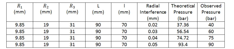
Following are the results of algorithm when used for rotor shaft assembly of different sizes. The tables show details of calculation data, observed pressure and theoretical pressure from algorithm. The graphs show readings for different interference for given rotor and their theoretical and observed pressure during press fit. As per Lame’s equation the press fit pressure is equal to press out pressure thus the max torque capacity of the assembly is ensured.
Table I
Fig. 3 Graph between pressure and radial interference for shaft diameter of tolerance limit 19.7 to 19.8mm
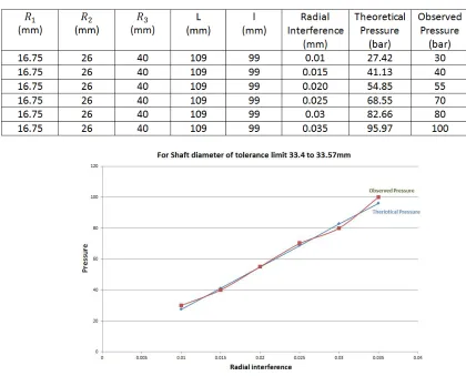
Table II
Calculation for radius 16.25 mm of internal diameter of rotor
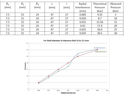
Table III
Calculation for radius 7.5 mm of internal diameter of rotor
Fig. 5 Graph between pressure and radial interference for shaft diameter of tolerance limit 15 to 15.1 mm
VII.CONCLUSION
The series of experiments provided relationship between the expected and actual pressure observed in pressure gauge and factors involved. The formula 1 and formula 2 can be employed to measure exact maximum pressure in pressure gauge with following consideration:
is taken as addendum of slots of aluminium die cast in slots in silicon stamping .
is taken as the difference in total length of rotor and the length where first pressure reading is observed in pressure gauge.
depends on the tolerance and taper of the shaft and can be controlled in manufacturing . This is major finding of the project that can be further employed for detailed research
in dynamic forces existing in interference fit. .
REFERENCES
[1] Shigley J.E. & MischkeC.R..Standard handbook of machine design, 17.13-17.14, McGraw-Hill, New York, 1988.
[2] Parsons B. & Wilson E.A., A method for determining the surface contact stresses resulting from interference fits. ASME, Journal of
Engineering for Industry, pages 208-218, February 1970.
[3] Peterson E. & Wahl A.M..Fatigue of shafts at fitted members with related photoelastic analysis. ASME, Journal of Applied Mechanics, 57,
[4] C.E.Truman and J.D.Booker, Analysis of a shrink fit failure on a gear hub/shaft assembly, Engineering Failure Analysis, 2006.
[5] G.Totten, M.Howes and T.Inoue, Handbook of residual stress and deformation od steel, ASM International, 2002
[6] D. Ramesh Rajkumar, Response of shrink fitted assemblies to dynamic torsion,25th International congress on conditioning monitoring and
diagnostic engineering, Journal of physics-Conference series 364(2012) 012124, 2012
[7] Kimball, A.L. Jr., 1925, “Measurement of Internal Friction in a Revolving Deflected Shaft,”, General Electric Review, 28, pp.554-558
Kimball, A.L. Jr., Lovell, D.E., 1926, “ Internal Friction in Solids,” Transactions of ASME, 48, pp.479-500
[8] Smalley, A.J., Pantermuehl, P.J., Hollingsworth, J.R., Camatti, M., , “ How Interference Fits Stiffen the Flexible Rotors of Centrifugal
Compressors,” IFToMM Sixth International Conference on Rotordynamics 2002.
[9] Murrenhoff, H.: Trends in Valve Development, O+P Ölhydraulik und Pneumatik, Vol. 46, Nr. 4.,pp. 1-36, (2003).
[10] Smith, D.: Hydraulic Presses,Smith& Associates, www.smithassoc.com/ copyrighted-white-papers/papers/C07.pdf, Monroe,Michigan,
pp.1-20, (1993).
[11] Nguyen, Q.H., Ha, Q.P., Rye, D.C.,Durrant-Whytel, H.F.: Force/Position Tracking for Electrohydraulic Systems of a Robotic Excavator,
Proc. of the 39th IEEE Conf. on Decision and Control,Dec. 12-15, Sydney, Australia,pp. 5224–5229, (2000).
[12] Dunnigan, M.W., Lane, D.M.,Clegg, A.C., Edwards, I.: Hybrid position/ force control of a hydraulic underwater manipulator,IEEE Proc. of
Control Theory Application, Vol. 143, No. 2., pp.145–151, (1996).
[13] Sun, P., Gracio, J.J., Ferreira, J.A.:Control System of a mini hydraulic press for evaluating spring back in sheet metal forming, Journal of
Materials Processing Technology, Vol. 176, pp. 55–61, (2006).