Feed-Forward System Control for
Solid-State Transformer in DFIG
Karthikselvan.T 1, Archana.S 2, Mohan kumar.S 3, Prasanth.S 4, Mr.V.Karthivel 5,
U.G. Student, Department of EEE, Angel College Of Engineering and Technology, Tirupur, Tamilnadu, India 1,2,3,4 Assistant Professor, Department of EEE, Angel College Of Engineering and Technology, Tirupur, Tamilnadu, India 5
ABSTRACT: This paper describes an energy feed-forward scheme, which takes the energy changes of inductors into consideration. Dual active bridge (DAB) controller is proposed for the feed forward system. (DFIG) double fed induction generator is used to provide the input supply for the system. When the load suddenly changes, there is large voltage deviation on the dc bus of the three-stage solid-state transformer. This system (feed-forward control) can effectively reduce the voltage deviation and transition time of SST. However, the conventional power of solid state transformer cannot develop the feed forward control without extra current sensors. A direct scheme, which directly passes the power of dab converter to the rectifier stage, is proposed for the rectifier controller. the dynamic performances of the two dc bus voltages should be improved.
KEYWORDS: DAB, Feed-Forward System, DFIG, Vienna rectifier, fuzzy controller.
I. INTRODUCTION
II. LITREATURESURVEY
Research has been carried out for the feed forward control, the tolerance of leakage inductor and the output inductors are analysed. Junjie Ge ,State Key Laboratory of Power System, Department of Electrical Engineering, Tsinghua University, Beijing, China has proposed a system with PI controller.
We proposed a system with (DFIG) double fed induction generator with vienna rectifier. Fuzzy controller is used to improve the efficiency of the feed forward system for the solid state transformer. We proposed the feed forward system with (DAB) dual active bridge and vienna rectifier.
In this paper we proposed a system with DAB, vienna rectifier, fuzzy logic controller for the feed forward system control for the effective reduction of the voltage deviation and transition time of SST.
III. EXISTING SYSTEM
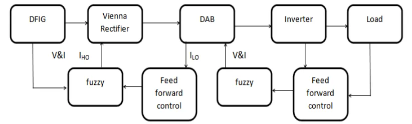
The mathematical model of three-phase three stage SST is provided. On this basis, the feed-forward control of SST is studied. Then, an energy feed-forward scheme and a direct feed-forward scheme are proposed for the DAB controller and rectifier controller to improve the dynamic performances of the two dc bus voltages without extra current sensor.
Fig. 1. Block diagram of existing system
Furthermore, the tolerances of the leakage inductor and the output inductors are analysed. At last, the experimental results which are in agreement with the theoretical analysis show that the proposed schemes can further reduce the voltage deviation and transition time.
IV.PROPOSEDSYSTEM
for the Vienna rectifier controller , Though the proposed control will increase a little computation complexity, the increased proportion is quite small in the whole complicated control of SST. Since only the feed-forward items are different and there is not any new variable which needs to be measured, the proposed control is easy to be implemented.
V. VIENNA RECTIFIER CONTROL
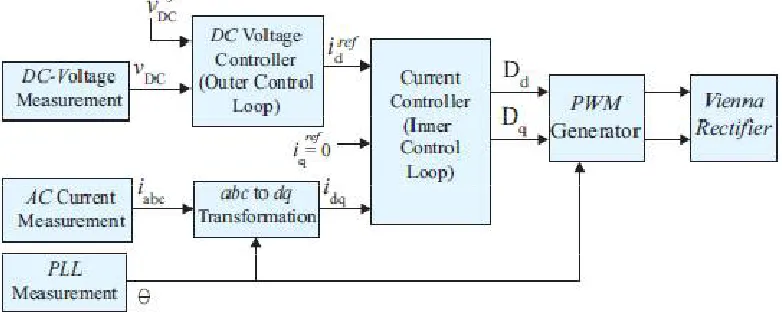
When using carrier-based pulse width modulation (PWM) and unity power factor the control of the Vienna rectifier is very similar to that of the full-bridge converter. The control employs a rotating reference frame synchronized with the ac- grid voltage vector by using a phase-locked loop (PLL). The voltages and currents occur as constant vectors in the d q reference frame in steady state. Considering the converter system connected to grid, the phase voltages and currents are given by the equation
where vabc, iabc, vabc,conv are ac voltages, currents and converter input voltages respectively. R and L are the resistance and filter inductance between the converter and the ac system. Assuming perfect synchronization with the grid voltage, the voltage equations in d − q synchronous reference frame are:
The subscript d and q stand for direct and quadrature respectively. In this configuration, the active and reactive power are controlled by the id and iq currents respectively. The control system is based on nested loops with fast inner current control loops and slower outer dc voltage control loop. The current reference for iq is set to zero for unity power factor. Similarly on the output side,
where Vdc and Idc are dc output voltage and current respectively. The grid voltage vector is defined to be along the d−axis direction, and then a virtual grid flux vector can be assumed to be acting along the q −axis. With this alignment,
vq = 0 and the instantaneous real and reactive power injected into or absorbed from ac system is given by,
Hence, the transformation into rotating d − q coordinate system oriented with respect to the grid voltage vector, leads to
a split of the mains current into two parts. One part determines the contribution which gives required power flow into the dc bus while the other part defines the reactive power condition. The equations (6) and (7) show directly the possibility to control two current components independently. The overall scheme is shown in Fig. 3.
Fig. 3. Overall scheme of vectorial Vienna rectifier control.
V. MATHEMATICAL MODEL OF SST
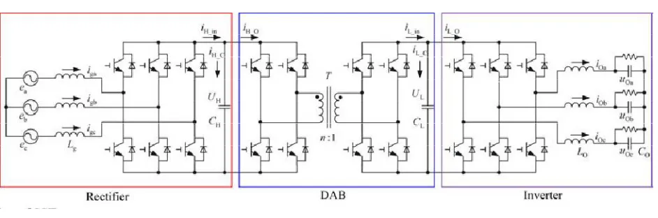
The configuration of three-phase three-stage SST is shown in Fig. 1, where Lg is the input inductor, CL and CH are the low-voltage and high-voltage dc bus capacitors, UL and UH are the low voltage and high-voltage dc bus voltages, iL in and iH in are the low-voltage and high-voltage dc bus input currents, i.e., the output currents of the DAB and rectifier converters, iL O and iH O are the low-voltage and high-voltage dc bus output currents, T is the high frequency isolation transformer, n is the transformer turns ratio, and LO is the output inductor. A SST is comprised of an ac–dc rectifier stage, a dc–dc DAB stage, and a dc–ac inverter stage.
Fig. 4. Configuration of SST.
More d-axis and q-axis components, i.e., igd and igq of the input current, iOd and iOq of the output current, uOd and
uOq of the output voltage, can be obtained through d-q transform as well. The mathematical model of the rectifier in
d-q coordinates is set up as,
where ω is the rotating speed, ud and uq are the d-axis and the q-axis components of the voltage vector generated by
the rectifier converter in SVPWM. Generally, eq is zero. When igq is regulated to be zero, according to the power
balance of input and output in the rectifier stage, there is
VI. SIMULATION RESULTS
The below figure shows the simulink model (front end) of the PROPOSED system.
The above characteristics shows the Output inverter side injection current and voltage waveforms.
VII. CONCLUSION
Feed-forward control can improve the dynamic performances of the dc bus voltages of SST. However, conventional feed forward scheme cannot develop the feed-forward control to the full without extra current sensors. In this paper we proposed an energy feed-forward scheme for the DAB controller and a direct feed-forward scheme for the rectifier controller. Though the proposed control will increase a little computation complexity, the increased proportion is quite small in the whole complicated control of SST. Since only the feed-forward items are different and there is not any new variable which needs to be measured, the proposed control is easy to be implemented.
REFRENCES
[1] M. D. Manjrekar, R. Kieferndorf, and G. Venkataramanan, “Power electronictransformers for utility applications,” in Proc. IEEE Inst. Aeronaut.
Sci. (IAS), 2000, pp. 2496–2502.
[2] X. She, R. Burgos, G. Y. Wang, F. Wang, and A. Q. Huang, “Review of solid state transformer in the distribution system: From implementation
to filed application,” in Proc. IEEE Energy Convers. Congr. Expo., 2012, pp. 4077–4084.
[3] A. Dannier and R. Rizzo, “An overview of power electronic transformer: Control strategies and topologies,” in Proc. Electr. Drives,
Autom.Motion, 2012, pp. 1552–1557.
[4] H.Wang, X. Tan, Q. Li, F. Zhou, Z. Deng, Z. Li, and N. Lu, “Development and applicability analysis of intelligent solid state transformer,” in
Proc.Electric Utility Deregulation Restruct. Power Technol., 2011, pp. 1150–1154.
[5] S. Xu, A. Q. Huang, andW. Gangyao, “3-D space modulation with voltage balancing capability for a cascaded seven-level converter in a
solid-state transformer,” IEEE Trans. Power Electron., vol. 26, no. 12, pp. 3778– 3789, Dec. 2011.
[6] S. Jianjiang, G. Wei, Y. Hao, Z. Tiefu, and A. Q. Huang, “Research on voltage and power balance control for cascaded modular solid-state
transformer,” IEEE Trans. Power Electron., vol. 26, no. 4, pp. 1154–1166, Apr. 2011.
[7] T. Zhao, G.Wang, S. Bhattacharya, and A. Q. Huang, “Voltage and power balance control for a cascaded h-bridge converter-based solid-state
transformer,” IEEE Trans. Power Electron., vol. 28, no. 4, pp. 1523–1532, Apr.2013.
[8] S.Xu, A. Huang, andN.Xijun, “Current sensorless power balance strategy for DC/DC converters in a cascaded multilevel converter based solid
state transformer,” IEEE Trans. Power Electron., vol. 29, no. 1, pp. 17–22, Jan.2014.
[9] M.Xiaolin, S. Falcones, and R.Ayyanar, “Energy-based control design for a solid state transformer,” in Proc. IEEE Power Energy Soc. Gen. Meet., 2010, pp. 1–7.
[10] M. Khazraei, V. A. Prabhala, R. Ahmadi, and M. Ferdowsi, “Solid-state transformer stability and control considerations,” in Proc. IEEE Appl.
Power Electron. Conf. Expo., 2014, pp. 2237–2244.
[11] Z. Tiefu, S. Xu, S. Bhattacharya, W. Gangyao, W. Fei, and A. Huang, “Power synchronization control for capacitor minimization in solid state
transformers (SST),” in Proc. IEEE Energy Convers. Congr. Expo., 2011,pp. 2812–2818.
[12] X. Wang, J. Liu, T. Xu, X. Wang, and L. Xiong, “Control of a three-stage three-phase cascaded modular power electronic transformer,”in Proc.