An Infrared Sensor Based Simple and Low
Cost Automatic Light Switching System
Damala Rajesh Babu
Assistant Professor, Department of Electrical and Electronics Engineering, GMR Institute of Technology,
Rajam, Andhraprahesh, India
ABSTRACT:Electricity has always remained a primary necessity of life as it is impossible to imagine our life without electricity. But the only problem, as far as electricity is concerned, the cost at which it is generated that is crossing all limits by every passing day, and thus undue the burden on the consumers in the form of higher electricity bills. There is a solution to manage energy efficient lightings at home door sensor for automatic lighting control is widely being developed for energy saving and it can also be used for security purposes. An infrared sensor based on electrical and electronics combinational circuit technology is used to develop the automatic light switching system. The automatic light switching system will lead to energy saving and efficient energy usage which could benefit every single individual. Here is a simple and low cost automatic door light circuit. The light automatically turns on when the door is opened and the light glows until the door is opened and whenever the door is closed the light automatically turns off.
KEYWORDS:Electricity,555 Timer, ULN2003 IC, 7805 Voltage Regulator, Bridge Rectifier,Step down transformer, UK3FF Relay, Receiver and Transmitter
I. INTRODUCTION
The In today’s world there is a continuous need for automatic appliances. The objective of this project is to make turn on the light itself automatically when the door gets opened and light will turn off automatically when door is closed. It can be used in general applications like in fridges and house appliances. In fridges when we open the door the light will turn on inside the fridge and whenever we close the door of the fridge it automatically turns off. In general house applications we can use this circuit at the main gate, when somebody opens the gate the speaker turns on and gives alarm indicating that someone had entered the gate. It can be done by using a speaker instead of led at the output. It can also be used for security purposes like using this circuit at the prisoner’s cell whenever a prisoner tries to escape the alarm will turn on and keeps the situation in alert. By using this circuit there is an advantage of preventing unwanted electric power wastage in some purposes and it is used for security purpose.
II. HARDWARE DESCRIPTION OF MAJOR COMPONENTS IN THIS TECHNOLOGY
A.555 Timer IC
Fig1.555 Timer IC
Pin 5 is also sometimes called the Control Voltage pin. By applying a voltage to the Control Voltage input one can alter the timing characteristics of the device..
B. Bistable Mode of the 555 Timer:
The 555 timer in bistable mode is also known as a flip-flop circuit. A flip-flop circuit alternates between two stable states, in this case the output of electrical current from the output pin. This is a fairly basic 555 timer circuit and unlike monostable mode and astable mode, it does not depend on a resistor and capacitor to set the timing of the circuit.
Fig2. 555 Timer Bistable Modes C. IC 7805 (Voltage Regulator IC)
7805is avoltage regulator integrated circuit. It is a member of 78xx series of fixed linear voltage regulator ICs. The voltage source in a circuit may have fluctuations and would not give the fixed voltage output.
Pin Description:
Pin
No Function Name
1 Input voltage (5V-18V) Input
2 Ground (0V) Ground
3 Regulated output; 5V (4.8V-5.2V) Output
Fig3. 7805 IC inner arrangement
As we have made the whole circuit till now to be operated on the 5V DC supply, so we have to use an IC regulator for 5V DC. And the most generally used IC regulators get into the market for 5V DC regulation use is 7805. So we are connecting the similar IC in the circuit as U1.IC 7805 is a DC regulated IC of 5V. This IC is very flexible and is widely employed in all types of circuit like a voltage regulator. It is a three terminal device and mainly called input , output and ground.In the circuit diagram C2 as well as C3 are filter capacitor while bypass capacitors are the C1 and C4.The electrolytic polarized capacitors are employed for this purpose. The purpose of filter capacitors normally 10mfd value of the capacitor used. And in these projects we also used 100mfd value of the capacitor. While in all kinds of circuit the value of bypass capacitor is 0.1 mfd. Generally un-polarized mainly disc capacitors employed for this purpose
.
D.ULN2003A IC: The ULN2003A is an array of seven NPN Darlington transistors capable of 500mA, 50V output. It
features common-cathode fly back diodes for switching inductive loads. It can come
in PDIP, SOIC, SOP or TSSOP packaging. In the same family are ULN2002A, ULN2004A, as well as ULQ2003A and ULQ2004A, designed for different logic input levels. A Darlington transistor (also known as Darlington pair) achieves very high current amplification by connecting two bipolar transistors in direct DC coupling so the current amplified by the first transistor is amplified further by the second one. The resultant current gain is the product of those of the two component transistors:The seven Darlington pairs in ULN2003 can operate independently except the common cathode diodes that connect to their respective collectors.The ULN2003 is known for its high-current, high-voltage capacity. The drivers can be paralleled for even higher current output. Even further, stacking one chip on top of another, both electrically and physically, has been done..
F.Relay
A relay is an electrically operated switch. Many relays use an electromagnet to mechanically operate a switch, but other operating principles are also used, such as solid-state relays. A type of relay that can handle the high power required to directly control an electric motor or other loads is called a contactor. Solid-state relays control power circuits with no moving parts, instead using a semiconductor device to perform switching. Relays with calibrated operating characteristics and sometimes multiple operating coils are used to protect electrical circuits from overload or faults; in modern electric power systems these functions are performed by digital instruments still called "protective relays".
Fig5. Relay pin Diagram
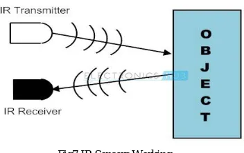
Fig6. Relay Connection G.IR Sensors
Infrared technology addresses a wide variety of wireless applications. The main areas are sensing and remote controls. In the electromagnetic spectrum, the infrared portion is divided into three regions: near infrared region, mid infrared region and far infrared region.The basic concept of an Infrared Sensor which is used as Obstacle detector is to transmit an infrared signal, this infrared signal bounces from the surface of an object and the signal is received at the infrared receiver.
F.
Types of IR SensorsFig7.IR Sensors Working
IR Transmitter:Infrared Transmitter is a light emitting diode (LED) which emits infrared radiations. Hence, they are called IR LED’s. Even though an IR LED looks like a normal LED, the radiation emitted by it is invisible to the human eye.
I.IR Receiver
:Infrared receivers are also called as infrared sensors as they detect the radiation from an IR transmitter.
IR receivers come in the form of photodiodes and phototransistors. Infrared Photodiodes are different from normal photo diodes as they detect only infrared radiation. The picture of a typical IR receiver or a photodiode is shown below.III.WORKINGPRINCIPLE
The circuit consists of two IC’s 555 timer IC and ULN2003 IC. The 555 timer is in bistable state. When we give 230v AC supply by using step down transformer the voltage is stepped down to 12v. The bridge rectifier converts the Ac to DC. The capacitor placed is used for filtering purpose so that we can eliminate the ripples in converted DC voltage and by using a voltage regulator 7805 the voltage is regulated to a fixed voltage of 5v. One LED is used to indicate the power supply. When receiver gets IR radiations the receiver is connected to 555 timer and so it triggers the IC and the output of the 555 timer is low and this output is sent to the ULN2003IC which consists of NOT gates so it gets a input of low which it is converted to high using not gate and this pulse is sent to the relay and the relay energises and turn on the load. Previously to indicate the de-energised state of relay a LED is used.
Fig9. Prototype for Automatic Light Switching System
IV.EXPERIMENTAL RESULTS
The following table1 describes how power is being saved in different places .the power savings in living room is 75%,bathroom is 65% and study room is 60%.
Fig10.Schematic Diagram of An Infrared Sensor BasedSimple and Low Cost Automatic Light Switching System
V. CONCLUSION
However, there is a solution to manage energy efficient lightings at home. Door sensor for automatic lighting control is widely being developed for energy saving and it can also be used for security purposes. An infrared door sensor based on electrical and electronics combinational circuit technology is used to develop the automatic light switching system. The automatic light switching system will lead to energy saving and efficient energy usage which could benefit every single individual.
REFERENCES
[1] S. S. S. Ranjit, A. F. Tuani Ibrahim, S. I MD Salim,and Y. C. Wong “Door Sensors for Automatic Light Switching System”2009 Third UKSim European Symposium on Computer Modeling and Simulation.
[2] Damala Rajesh Babu; V. SrikanthBabu; TerliSatyanarayana.”Tracker robot using dual tone multiple frequency (DTMF) and microcontroller” IEEE 10.1109/EESCO.2015.7253772,978-1-4799-7676-8.
[3] Ramesh Lal Das, ShishirRanjan, and Sreenivasappa B. V., Member, IEEE. Energy Saving Smart Light Switching System.
[4] Aurele J. Maillet, Member, IEEE “Energy-Efficient Lighting and Lighting Practices for the Pulp and Paper Industry” IEEE transactions on industry applications, vol. 28, no. 4, July / august