Horizontal Drilling Well Proposal in West
Qurna Oil Field (Iraqi Oil Field)
Ayad A. Al-Haleem1, Abdul-Aali Al-Dabbaj2,Firas Mohammed Hadi3
Assistant Professor, Department of Petroleum Engineering, College of Engineering, Baghdad University, Baghdad,
Iraq1
Associate Professor, Reservoir Management, Ministry of Oil,Baghdad,Iraq2
Petroleum Engineer, South Oil Company, Basra, Iraq3
ABSTRACT:Depending on the information of some drilled wells in West Qurna oil field (404 vertical , WQ-416directional and WQ-271 directional high angle deviated well) and horizontal well (HF-69) in Halfaya oil field and studying all the factors affecting the hole cleaning beside the field observations with experience , a horizontal drilling program for West Qurna oil field was prepared. This study aims to introduce a plan to drill a horizontal well in West Qurna oil field due to absence of such well type. This proposal consists of complete drilling plan start by bottom hole assembly (BHA design), casing seat with cementing operation, and mud properties. The available geological information was taken into consideration during the design of the present proposal.
.
KEYWORDS:West Qurna, BHA, Horizontal well, Hole cleaning, Bit.
I. INTRODUCTION
Hole cleaning and the problems due to poor hole cleaning are the most important issues which happened especially in directional and horizontal oil wells. The authors in [1] found that the yield point /plastic viscosity (YP/PV) should be as high as possible to better hole cleaning .In [2],the authors performed an experimental study of lifting cuttings in the deviated wells. In their research, they used a 40 feet (12.2 m) pipe. Several types of drilling fluids and different flow regimes were tested. The concept that insufficient hole cleaning is responsible for a large portion of all stuck pipe and some would argue that it is the number one cause of stuck pipe around the world, especially in high - angle holes was introduced by [3] . A new mathematical method for estimating the minimum fluid transport velocity for system with the inclination between 55° to 90°was developed by [4]. A study on improving cuttings transport capacity of drilling fluid in a horizontal wellbore by attaching air bubbles to the surface of drilled cuttings by using chemical surfactants was performed by [5]. The effects of hydraulic factors on cuttings transport and hole cleaning and analyzed data using experimental facilities in a 70 cm 5 m long flow using water and water solutions of Carboxy Methyl Cellulose (CMC) was studied by [6] . The authors in [7] have investigated that the effect of fluid rheology and cuttings sizes on the circulation rate required ensuring that the drilling cuttings in horizontal wells are efficiently transported to the surface. In [8], an extensive experimental study on model development for cuttings transport in highly deviated wellbores was implemented. The influence of the following variable was also investigated: flow rate, inclination angle, mud rheological properties and mud weight, cuttings size, drill pipe eccentricity, and ROP. The mechanism of an active hydro clean drill pipe (EHCDP) for transport cuttings and hole cleaning was introduced by [9].
slow rates of penetration and difficulty running casing and logs.The study done by [12]showed that horizontal drilling is expensive, and when combined with hydraulic fracturing a well can cost up to three times as much per foot as drilling a vertical well. Also extra cost is usually recovered by increased production from the well.
In this study a new plan to drill a horizontal well in West Qurna oil field is suggested since the West Qurna field lacks the presence of horizontal wells. West Qurna oil field is one of the largest oil fields in Iraq with reserve about 43 billion barrel of crude oil. It located in the south-eastern part of Iraq, approximately 50 km north-westwards from Basra and 30 km from Zubair oil field. The oil field is situated at the lower part of largest Asian Tigris-Euphrates river system, along the Shatt Al-Arab waterway formed by confluence of the Tigris and the Euphrates rivers.
II. DESCRIPTIONOFHORIZONTALWELLDESIGN
Selection of horizontal well Profile
Absolutely, the available information of the drilled wells and the analyzing concerning with all the drilling variables which relates to lifting capacity and hole cleaning , all aims to select a single arc profile short radius type to design the suggested horizontal well .In this design, the hole angle is built up from zero at the kick off point (KOP) to 90 degrees at the entry point into the reservoir, consisting of vertical-build-horizontal sections use only one rate to build up the hole inclination from 0 degree to maximum. If this design has been used, the buildup tendencies of both the formation and the rotary or steerable BHA should be known in order to avoid missing the target due to excessive or insufficient build up rates. Also the build-up rate (BUR) should be selected to land exactly on the target.
The present proposal consist of four holes , starting first hole using bit 26" to drill then running in hole casing 20" and then cemented to surface . The goal is to isolate formation having sloughing shale and caving. The second hole 17.5" bit can be used to drill, then running in hole casing 13.375" and then cemented to surface.
The objective of casing is:
1. Isolate the upper lost circulation formation (Dammam), and to prevent hole collapse in the upper interval when the loss circulation happens.
2. Isolate the formation having sulphure water (Umm Erradhuma and Tayarat formations) to prevent tight hole in Shiranish formation, cement to surface.
The 3rd hole using bit 12.25" to drill the curvature hole to top of Mishrif formation and running in hole 9.625" casing , using the stage collar to cement .Finally a hole 8.5" bit can be used to drill the production formation (pay zone) of Mishrif (horizontal interval) and open hole completion.
Recommended Bits
Based on the bit information analysis from the drilled wells in this field, the following drill bits are recommended to drill the suggested well as shown inTable 1.
Table 1: Recommended bit kinds for the suggestion horizontal well
Hole Size Bit Size IADC code
26" Hole 26" 111
17.5" Hole 17.5" 517
12.25" Hole 12.25" 527
12.25" Hole 12.25" 537
8.5" Hole 8.5" 517 or 537
The suggested bits may be changed according to the performance of previous bit runs and available bits on site.The rock drill ability for most formations above cretaceous is good , thus PDC bit with down hole motor can be used to shorten the drilling period and minimize down hole complex .
Building up Interval
Steerable BHA consisting of MWD and single bend motor can be used in this interval (12.25"hole ) with a maximum hole deviation of 55-60°.
Casing Program
Figure (1) illustrates the diagram of casing program for the suggested horizontal well which show the depth of formations with the casing sizes.
Following the details of BHA for 12.25" hole:
12.25" bit + 8" (1.25-1.5°) single bend motor + flapper valve + 8"NDC (one joint) + 8"MWD + 5"NHWDP (two joints) + 5"HWDP (six stands) + drilling jar + 5" HWDP (two stands) + 5" DP
Data sheet of casing program and brief description of cementing operation are listed in Appendix (B)
Horizontal Interval
Drill out the 9.625"casing collar / shoe without motor and LWD. POOH to change BHA as listed below, further drill 65-100 ft of holding section then build up to 90°.
BHA : 8.5" or 8.375" bit +6.75" (1-1.25°) single bend motor+ flapper valve + 6.75" LWD + 5" NHWDP (two joints) + 5" DP (70 joints)+ 5" HWDP (nine stands)+Jar + 5" HWDP (five stands) + 5" DP
Single bend motor: 1 or 1.25° Building rate: 3 – 6° /100feet
Drilling operation: Slide drilling and rotary drilling mode is used for hole cleaning bed, and to correct the hole trajectory timely by adjusting tool face. The hydraulic motor is rotated by a flow rate of the drilling fluid down the drill pipe. Also rotate the drill bit without revolving the drill string. This permits the bit to drill a direction that deviates from the direction of the drill string.After installed the motor the drill bit and drill pipe are reduced back down the well and the bit drills a direction that guides the well bore from vertical to directional or horizontal above a distance about many hundred feet. When the well has been turned to the proper angle, straight-ahead drilling continues and the well follows the goal rock unit. Observance the well in a thin rock unit needs careful steering. Down hole tools are used to determine the azimuth and the drilling direction. This data is used to direct the drill bit.
Fig.1. Show the Casing Program for the Proposal Horizontal well in West Qurna oil field
Casing 20" @ 2624 ft
Casing 13.375"@6390
ft
The KOP @
6725 ft and Casing 9.625 "
at top of Mishrif Conductor Pipe
30" @ 328 ft
Drilling Fluid Program
1. Drilling Fluid System For The First and Second Holes
There are some dolomite , anhydrite and marl in the second hole formation , however , according to the information collected , it has influence on the drilling fluid 's parameters and there is many problems happened (losses in Dammam formation , Sulpher water in Tayarat formation , marl in Shiranish formation ) 2. Drilling Fluid System for Build- Up And Horizontal Sections
Polymer drilling fluid system can be recommended to be used in the build-up and horizontal sections. The polymer drilling fluid system, prevent the forming the cutting beds and keep the boreholes stable and good lubrication. In the build-up and horizontal sections, the following two issues must be taken into consideration: 2.1. Lubrication
Lubrication issue is the most important when drilling horizontal wells. As the inclination angle and horizontal displacement of horizontal well are much larger than the normal direction wells , especially when the inclination angle beyond 50° the contact area between the tools and the borehole increases sharply , so there is more possibility of pipe sticking . Three types of lubricant are usually used, solid lubricant extreme pressured lubricant and oil lubricant. The solid lubricant includes graphite and small plastic ball, which attribute to physical lubrication.
2.2 Hole Cleaning
In order to prevent forming of cuttings bed, pump rate, annular velocity, and some rheological parameters of the drilling fluid must be controlled. At the same time, after drilling one single it should be reamed back for one or two times, and wiper trips should be made within the feet's of drilled new hole.
Recommended Flow Rate with Hole Size forthe Proposal Horizontal Well in West Qurna Oil Field
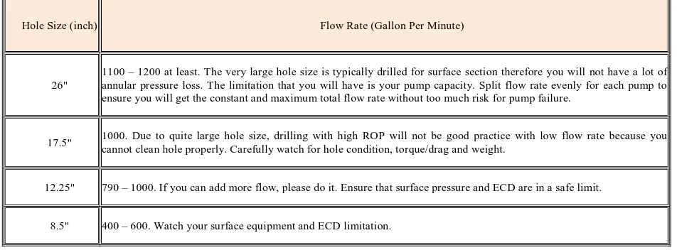
In the suggested horizontal well, the recommended values take into consideration the diameter of each hole size and other hole conditions in order to have a proper hole cleaning. Some guide lines have been also mentioned with the recommended values, Table (2).
Table (2) Hole size with recommended flow rate
Hole Size (inch) Flow Rate (Gallon Per Minute)
26"
1100 – 1200 at least. The very large hole size is typically drilled for surface section therefore you will not have a lot of annular pressure loss. The limitation that you will have is your pump capacity. Split flow rate evenly for each pump to ensure you will get the constant and maximum total flow rate without too much risk for pump failure.
17.5" 1000. Due to quite large hole size, drilling with high ROP will not be good practice with low flow rate because you cannot clean hole properly. Carefully watch for hole condition, torque/drag and weight.
12.25" 790 – 1000. If you can add more flow, please do it. Ensure that surface pressure and ECD are in a safe limit.
8.5" 400 – 600. Watch your surface equipment and ECD limitation.
Schedule Plan
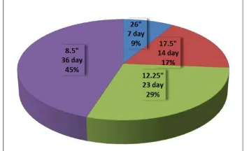
Depends upon the drilled wells information and the oil field observations with the practical experience a schedule plan required to drill different sections of the suggested horizontal well can be listed as following:
Casing shoe at (895 m MD / 887 m TVD), drilling, cementing, (7 Days). 2- For 17.5" hole (±49 ft) TVD below top of Sadi formation. Casing shoe drilling, survey, tripping, (14Days).
3- For 12.25" Building and holding section (9492 ft MD / 9060 m TVD),drilling, survey, tripping 19 Days &circulation, risk, misc. (4Days) and the total is 23 days.
4- For 8.5"horizontal interval drilling,survey, tripping 24 Days, circulation ,risk, 5 Days & clean out, logging, (7 Days), (total 36 days).
So the Total time is 80 days, Fig(2).
A statistical representation of time Vs hole size for the present well plan have been shown in figure (2).
Figure (2) Pie chart represent time vs. hole size for the proposal of horizontal well in West Qurna oil field
III.CONCLUSIONS
Based on the theoretical and experimental observations and analysis, the following conclusions can be drawn regarding optimization of hole cleaning in horizontal oil well:
1- Throughout this work, it is apparent that there are optimum limits of some drilling parameters to have an efficient practical removal of cuttings or satisfied hole cleaning. Generally, from the results of this study and field investigations, it was found that the best values to drill the horizontal holes can be summarized as shown in Table 3:
Table 3. Optimum limits of drilling parameters
2- A complete drilling plan for the case of horizontal well of short radius type in West Qurna Oilfield have been suggested. The purpose behind that is to get the benefits associated with horizontal drilling like drilling time and total cost.
3- The F.W.B. drilling fluid system can be used to solve the problems in the surface and the first hole such as loss circulations of the Dammam formation, the calcium ion contamination and caving in the Lower Fars Formation. Polymer Mud drilling fluid system also can be used to solve the problems in the second hole such as flow of sulpher water in Tayarat formation.
8.5" 12.25"
17.5" 26"
Hole Size
500 800
1000 1200
Flow Rate(gpm)
22-30 15-20
21 22
Yield point (lb/100ft2)
10.4 9.75
9.5 8.9
Mud Weight(ppg)
10.5-11 10-10.5
10.5 9-10
PH
60-80 110-120
50-70 100-120
RPM
ALAP 15-20
ALAP -
IV.RECOMMENDATIONS
Some of the issues which should be investigated in future studies are listed below:
1- OBM or Polymer drilling fluid system has the outstanding abilities on cuttings lifting,lubrication, hole cleaning etc, so it is very important to be used for the successful drilling in the build- up and horizontal sections.
2- In cases, where drill pipe does not rotate, it is difficult to remove cuttings bed. In these situations, wiper trips are necessary to improve hole cleaning. Usually, a normal range of drill pipe rotation is around 90 to 180 rpm. The pipe can rotate up to 120-rpm when drill bit is on-bottom, and 180-rpm drill bit is off-bottom.
3- In unstable formations, like sandstone, a high rpm values should be avoided, since the drill string rotations can cause loss of some parts of wellbore formation (washouts). In addition, high rpm can cause high vibration in the drill string and thus, damage the electronics part in the BHA, like Geo-Pilot or the MWD tools. 6- One has to be aware that inclinations between 40° to 45° degrees are critical since cuttings can slide down during e.g. connections when pumps are off.
4- In the wellbore with inclination angle from 0° to 45° degrees, laminar flow in annulus and increasing yield value of mud to its limit is recommended.
5- Small cuttings create more packed cuttings bed. The height of cuttings bed is higher at inclination between 65° to 70° degrees, since hole cleaning is more difficult in this interval. In this case, a high rotary speed with a high viscosity mud would benefit to transport small-sized cuttings. When the drill pipe does not rotate, a low viscosity mud cleans the wellbore better than high viscosity mud.
.
NOMENCLATURESANDABBREVIATIONS
API : AmericanPetroleum Institute BHA : Bottom Hole Assembly
BUR : Build Up Rate (angle/100ft) CMC : Carboxy-Methy1-Cellulose
DP : Drill Pipe (inch) DC : Drill Collar (inch)
DH : Hole Diameter (inch) ECD : Equivalent Circulating Density (ppg) EHCDP: Effective Hydro Clean Drill Pipe
ERD : Extended- Reach Wells FWB : Fresh Water Bentonite GPM : Gallon per Minute HWDP : Heavy Weight Drill Pipe
IADC : International Association Drilling Contractor KOP : Kick Off Point
LCM : Lost circulation materials MWD : Measuring While Drilling
MW : Mud Weight (ppg) MD : Measured Depth (ft) NDC : Nonmagnetic Drill Collar
NHWDP: Nonmagnetic heavy weight drill pipe
PV (µp): Plastic Viscosity (cp) POOH : Pull Out Of the Hole
Ps : Pressure Losses in Surface Connections (psi)
RIH : Running In the Hole
TVD : True Vertical Depth (ft) WQ : West Qurna field
WOB : Weight on Bit (Ton) YP : Yield Point (Lb/100ft2) ϼ : Mud Density (ppg)
APPENDIX A
Bottom Hole Assembly Details Vertical hole:
17 1/2" Hole BHA:
171/2" bit +9" D.C (3jts) + 8" spiral DC (3jts) + 5" HWDP (5Stands) + 5" DP Drilling Parameters:
WOB = 5-10 Ton, Rotation = 80-100 RPM, Pump Rate = 872-1000 gpm
12 1/4" Hole BHA:
12 1/4" bit +8" NDC (1jt) + stabilizer 12 3/16" + 8" spiral DC (12jts) + 63/4" DC (9 jts) + 5" HWDP (5Stands) + 5" DP Drilling Parameter:
WOB = 10-15 Ton, Rotation = 80-130 RPM, Pump Rate = 713-793 gpm
81/2" Hole BHA:
81/2" bit +61/2" NDC (1jt) + stabilizer 6 7/16" + 61/2” DC (2jts) stabilizer 6 7/16" + 61/2” DC (9jts) + 5" HWDP (5Stands) +5" DP
+
Drilling Parameters:
WOB = 10-15 Ton, Rotation = 80-130 RPM, Pump Rate = 475 - 555 gpm
APPENDIX B
Casing Program and Cementing Operation Cementing Casing Operation:-
Although there is anhydrite and Dolomite in the location, its influence to the properties of cement slurry is minor to the shallow depth and relatively low bottom hole temperature, thus fresh water cement slurry can be used for cementing the whole interval. Cement system of loss controlling and plugging functions is used for the production casing.17.5" hole surface casing cementing. It is drilled to 2433ft and run in the 133/8" casing to depth 2429 ft, cement to surface. Use only neat cement, without any cement additives.
12.25"hole intermediate casing cementing. 12.25" bit is used to drill into the formation of Saadi and run the 95/8" casing into 49 ft ofsaadi, the circulation temperature is 50-60°C. Cement system of dual densities and dual cementing time is selected due to the long interval and lost circulation prevention measures should be taken for the lower part.
Upper part: Light weight cement, cement + fluid loss agent + early strength agent + dispersing agent + bentonite + stabilizing agent.
Lower part: Cement slurry of loss control and plugging functions with normal weight, cement + fluid loss agent + early strength agent + dispersing agent + loss control / plugging agent.
8.5" Hole Casing/Liner Cementing: 1- For 7" liner
Cement slurry of normal weight, the key is to control the free water of the slurry and lost circulation. Cement + fluid loss agent + dispersing agent + retarder + plugging agent + deforming agent
2- For 7" full casing, cement to surface.
Lower part: cement + fluid loss agent + retarder + dispersing agent + plugging agent + deforming agent.
REFERENCES
[1] Okranji, S.S. and Azar J.J., “Mud Cutting Transport in Directional Well Drilling”, paper Society of Petroleum Engineers (SPE) 14178,
presented at the annual meeting in Las Vegas, Nevada, Sept. 22-25, 1985.
[2] Tomren, P.H., Iyoho, A.W., and Azar, J.J., “Experimental Study of Cuttings Transport in Directional Wells,” SPE paper, (43-56), 1986.
[3] Sifferman, T.R., &Becker T.E, "Hole Cleaning in Full-Scale Inclined Well Bores", SPE 20422, 65th Ann.Tech.Conference of SPE in New
Orlands, Sept. 1990.
[4] Larsen et. al., “Development of a New Cutting Transport Model for High – Angle Wellbores Including Horizontal Wells”, paper SPE 25872,
June 1997.
[5] Yu, M., Melcher, D., Takach, N., Miska, S.Z., and Ahmed, R., “A New Approach to Improve Cuttings Transport in Horizontal and Inclined
Wells,” paper SPE 90529 presented at the SPE Annual Technical Conference and Exhibition, Houston, September 26 – 29 ,2004.
[6] V.C. Kelessidis, and G.E. Mpandelis, "Hydraulic Parameters affecting cuttings transport for Horizontal Coiled Tubing Drilling”, presented at
the 7 th National Congress on Mechanics, , pp. 1-9,2004.
[7] Al-Zubaidi , N. S. ," Experimental Study of Cuttings Transport in Horizontal Wells," Ph.D. Dissertation , Univ. of Baghdad , Iraq , 2007.
[8] Mirhaj, S.A., Shadizadeh, S.R., and Fazaelizadeh, M.,“Cuttings Removal Simulation for Deviated and Horizontal Wellbores,” paper SPE
105442 presented at 15th SPE Middle Oil & Gas Show and Conference, Bahrain, March 11 – 14,2007.
[9] F. Chen, Q.F Di, P.B Yuan, W.C. Wang, J.L. Yao, Y.Q. Zhou, andG.X. Zhai, "Mechanism of an effective hydroclean drill pipe for hole cleaning", ACTA Petrolei Sinica, vol. 33, pp. 298-303, 2012.
[10] E. Cheung, N. Takach, E. Ozbayoglu, R. Majidi, and B. Bloys ,Improvement of Hole Cleaning Through Fiber Sweeps, at the SPE, Deep Water
Drilling and Completions Conference, pp. 1-11,2012
[11] A.Z. Noah " Optimizing Drilling Fluid Properties and Flow Rates for Effective Hole Cleaning at High- Angle and Horizontal Wells "Journal
of Applied Sciences Research, 9(1): 705-718, 2013 ISSN 1819-544X.
[12] Bern, P.A., et al., Modernization of the API Recommended Practice on Rheology and Hydraulics: Creating Easy Access to Integrated