Determining the Location of Rapid Exit
Taxiways Using Three Segment Method
Kale Sahil Rammohan1, Kurulekar Maya Mahesh2
Student, Department of Civil Engineering, MIT College of Engineering, Pune, Maharashtra, India1
Assistant Professor, Department of Civil Engineering, MIT College of Engineering, Pune, Maharashtra, India2
ABSTRACT: This study is intended to guide airport designers to determine the location of rapid exit taxiways (RET’s) along the length of a runway using thethree-segment method as specified in the codes given by the International Civil Aviation Organization (ICAO). The various aeronautical esoteric terminologies have been explained in a lucid manner to ensure that civil and transportation engineers can conveniently comprehend the steps required to locate rapid exit taxiways as per the provisions in the codes. The procedural steps have been explained using an explanatory model to facilitate better understanding of the design methodology. Suitable design and safety checks are provided at various places along the procedural steps for the explanatory model.
KEYWORDS: Runway, Rapid Exit Taxiway, International Civil Aviation Organization, ICAO Annex 14, ICAO Aerodrome Design Manual Part 1 and Part 2
I. INTRODUCTION
Rapid exit taxiways (RET’s) are taxiways that are provided along the length of a runway to facilitate a faster exit from the runway at high speeds. Owing to rapid exit taxiways, the occupancy time of aircrafts on the runway is reduced and there is an increase in the overall efficiency of the runway due to its increased capacity.
The detailed geometric design of rapid exit taxiways is specified clearly in ICAO Annex 14 and ICAO Aerodrome Design Manual Part 2 and is not included in the scope of this informative paper.
In this paper, the steps required to calculate the distances along a runway where rapid exit taxiways are located are mentioned along with the referred references from the codes. The various codes referred are given as follows-
1. ICAO Annex 14 (Sixth Edition, July 2013)
2. ICAO Aerodrome Design Manual Part 2- Taxiways, Aprons and Holding Bays (Fourth Edition, 2005)
The data pertaining to the geometric design of the runway used for the explanatory model is assumed suitably for easier calculations. This data assumed includes but is not restricted to the following information-
1. Declared distances of the runway under consideration
2. Width of the runway
II. RELATEDWORK
the airport when the horizontal spacing between the parallel taxiway and runway did not meet the standard rapid exit taxiway design requirements. The methodto improve the flexibility of ground dispatching and enlarging the runway capacity by using rapid exit taxiway to take off have been systematically discussed by WANG Wei and LEI Zhen-Jun[9]. Through analysis of aircraft landing process, WANG Wei and DENG Song-wu[10] developed an optimized model of runway high-speed exit. By applying computer simulation method to the analysis of the model, the optimized exit location is determined under specified conditions.
III.DATAREQUIREDANDASSUMPTIONS
1. The runway under use is an active runway with continuous traffic, capable of handling narrow as well as wide bodied airliners.
2. The runway is instrumental with precision approach facilities well suited for instrumental as well as visual approach procedures.
3. The runway orientation and designation completely complies with the recommendations stated in the ICAO Annex 14 and ICAO Aerodrome Design Manual Part 1 (Third Edition, 2006).
4. The runway length is calculated after integrating the corrections for elevation, temperature and gradient.
5. ICAO Airport Code – 4F
6. The runway end designations are 10 and 28.
7. No tailwind is acting along the runway.
8. Gradient of the runway is 0.2%
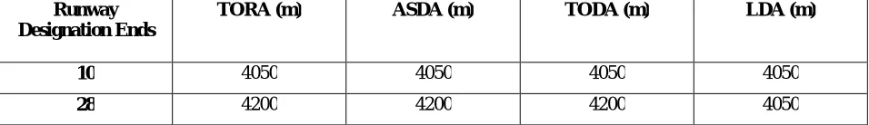
9. The declared distances of the runway are given in the table below-
Table 1: Declared Distances
Runway Designation Ends
TORA (m) ASDA (m) TODA (m) LDA (m)
10 4050 4050 4050 4050
28 4200 4200 4200 4050
IV.STEPWISEPROCEDURETODETERMINETHELOCATIONOFRET’S USINGEXPLANATORY RUNWAY/MODEL
In order to determine the location of the rapid exit taxiways along a runway, it is necessary to understand the three-segment method as given in the ICAO.
The segments of the three-segment method are essentially the distances along a runway that need to be added consecutively to determine the point of turnoff of the rapid exit taxiway from the respective runway end. The segments are described as follows-
Segment 1: Distance required from landing threshold to main gear touchdown (S1)
Segment 2: Distance required for transition from main gear touchdown to establish stabilized braking configuration (S2)
Segment 3: Distance required for deceleration in a normal braking mode to a nominal turnoff speed.
Refer figure 1-15 given on page number 1-33 of ICAO Aerodrome Design Manual Part 2 for detailed segment diagram.
Explanation of Segmental Distances
S1 is the distance from the displaced threshold of a runway to the point where the main landing gear initially touches
the runway surface. During this time, the aircraft is above the runway but not on the runway.
S2 is the distance from the point where the main landing gear touches the runway surface to the point along the runway
when the pilot applies brakes/thrust reversals. The application of brakes/thrust reversals may be before or after the nose gear touches the runway surface. It is followed by S1.
S3 is the distance required by an aircraft to reach the nominal turnoff speed after deceleration caused due to
brakes/thrust reversals. It is followed by S2.
Thus, S1 + S2 + S3 is the distance corresponding to the ideal location of a rapid exit taxiway along the length of the
runway from the respective runway ends.
In this paper, the three-segment method is applied using the principle of aircraft approach categories as specified in the ICAO.
Step 1- Identification of Aircraft Category based on Approach
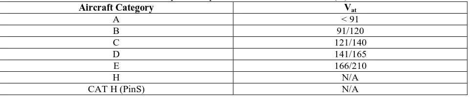
Table 2: Speeds for procedure calculations in knots (kt)
Aircraft Category Vat
A < 91
B 91/120
C 121/140
D 141/165
E 166/210
H N/A
CAT H (PinS) N/A
In the above table, Vat – Speed at threshold based on 1.3 times stall speed Vso or 1.23 times stall speed Vslg in the
landing configuration at maximum certified landing mass. (Not applicable to helicopters.)
(Excerpt taken and referred from Table I-4-1-2, Page/Section I-4-1-7, ICAO Aircraft Operations, Volume 1: Flight Procedures, Fifth Edition, 2006)
Design of Explanatory Model
Since the rapid exit taxiway is to be used at a code 4F airport, the aircraft category based on approach is thus selected as C and D for runway.
{Aircraft category C and D include medium to large, narrow/wide bodied aircrafts} Thus, provide 2 rapid exit taxiways for category C and D aircrafts from both runway ends.
Step 2- Calculating Segmental Distances (ICAO Aerodrome Design Manual Part 2, Page 1-33 and 1.34)
For calculating S1 -
S1 is empirically derived firm distance to mean touchdown point, corrected for downhill slope and tailwind component
as applicable-
For Aircraft Category C and D; S1 = 450 m
Correction for slope = +50 m/-0.25% Correction for tailwind = + 50 m/+5 kts
For Aircraft Category A and B; S1 = 250 m
Correction for slope = +30 m/-0.25% Correction for tailwind = + 30 m/+5 kts
Design of Explanatory Model
S1 = 450 m as aircraft category is C and D.
For calculating S2
-S2 or the transition distance is calculated for an assumed transition time (empirical) ∆t = 10 seconds at an average
ground speed of
S2 = 5 X (Vth – 10) ……where Vth is in kts
In the above equation, Vth is the threshold speed based on 1.3 times stall speed of assumed landing mass equal to 85 per
cent of maximum landing mass. Speed is corrected for elevation and airport reference temperature.
Design of Explanatory Model
The aircraft categories based on approach is not going to change if the assumed landing mass is taken equal to 85 per cent of maximum landing mass. Also, as per the mentioned assumption, the runway length is calculated by including the corrections for elevation and temperature so there is no need to correct the speed for elevation and airport reference temperature. Thus, as per figure 1-15, Page 1-33, Aerodrome Design Manual Part 2, Vth = 1.3 times Vstall or Vso,
Taking Vat = Vth,
S2 = 5 X (140 – 10) = 650 m …... for category C aircrafts
(Max. value of Vat for category C aircrafts is 140 kts according to table 2)
S2 = 5 X (165 – 10) = 775 m …… for category D aircrafts
(Max. value of Vat for category D aircrafts is 165 kts according to table 2)
For calculating S3
-S3 or the braking distance is determined based on an assumed deceleration rate (a) according to the following equation
S3 = {(Vth – 15)2 – Vex2}/8a
Where Vex is the nominal turnoff speed:
Code number 3 or 4: 30 kts Code number 1 or 2: 15 kts
Design of Explanatory Model
According to ICAO, deceleration rate of a = 1.5 m/s2 is considered a realistic operational value for braking on wet runway surfaces.
Wet surfaces are taken for designing purposes to consider an additional factor of safety. Thus,
S3 = {(140 – 15)2 – 302}/ (8 X 1.5) = 1227.08 m …... for category C aircrafts
S3 = {(165 – 15)2 – 302}/ (8 X 1.5) = 1800 m …... for category D aircrafts
Thus, point of turnoff for category C aircrafts = S1 + S2 + S3 = 450 + 650 + 1227.08 = 2327.08 m …… say 2330 m
(round off)
Point of turnoff for category D aircrafts = S1 + S2 + S3 = 450 + 775 + 1800 = 3025 m
Design Checks
For both the above cases, the point of turnoffs from the runway ends < LDA from both runway ends (4050 m).
Hence, the check is satisfied.
The points of turnoff essentially act as the beginning of centrelines of the corresponding rapid exit taxiways. Thus, the centreline checks must be provided for rapid exit taxiways used by category C aircrafts and category D aircrafts. Distance between the two corresponding rapid exit taxiways = 3025 – 2330 = 695 m
Centre to centre distances between taxiways required = 97.5 m for type F airports {Referred from ICAO Annex 14, Table 3-2, Page 3-22)
Since 675 m > 97.5 m
The check is satisfied.
V. SUMMARYOFLOCATION
Table 3-Distance of RET’s in meter RUNWAY END DESIGNATION DISTANCE OF RET SUITABLE
FOR CATEGORY C AIRCRAFTS
DISTANCE OF RET SUITABLE FOR CATEGORY D AIRCRAFTS
10 2330 (from Displaced Threshold) 3025 (from Displaced Threshold) 28 2330 (from Runway End) 3025 (from Runway End)
In the above table, it is important to note that runway end 10 has a displacement having length 150 m (can be inferred from Table 1. Thus, the distances of rapid exit taxiways from runway end 10 are calculated from the displaced threshold.
VI. CONCLUSION
REFERENCES
[1] Kale Sahil Rammohan, Kurulekar Maya Mahesh, “Design Procedure of an Airport Layout according to International Standard Codes”, International Research Journal of Engineering and Technology, Vol-3, Issue-12, pp. 1505-1512, December 2016.
[2] Kaustubh Wakhale, Sameer Surve, Rohit Shinde, “Design of Airport Runway by International Standards”, International Journal of Advances in Science, Engineering and Technology, Vol-2, Issue-3, pp. 106-110, July 2014.
[3] Paul Roosens, “Congestion and Air Transport: a challenging phenomenon”, European Journal of Transport and Infrastructure Research, Vol-8, Issue-2, pp. 137-146, 2008.
[4] Joseph I. Daniel, “Benefit-cost analysis of airport infrastructure: the case of taxiways”, Journal of Air Transport Management, Vol-8, Issue-3, pp. 149-164, May 2002.
[5] Jamaluddin Rahim, “An Analysis of Runway Capacity at International Airport Sultan Aji Sulaiman Balikpapan in East Kalimantan-Indonesia”, International Refereed Journal of Engineering and Science, Vol-4, Issue-5, pp. 5-11, May 2015.
[6] Alexandre L. W. Bradley, “Airport apron, runway and taxiway design”, The Independent Airport Planning Manual, pp. 81-100, 2010. [7] P. J. McCullagh, N. Namachivayam, “Design and Construction of a New Taxiway Junction with an Existing Runway Using Expedient
Pavement at Mumbai International Airport, India”, 2013 Airfield & Highway Pavement Conference, 2013.
[8] LI Mingjie, “Graphic Design Method for the Non-Standard Rapid Exit Taxiway” Journal of Chongqing Jiaotong University (Natural Science), Vol-35, Issue-3, pp. 43-46, 2016.
[9]WANG Wei, LEI Zhen-Jun, “Discussion on aircraft taking-off by rapid exit taxiway”, Journal of Civil Aviation University of China, Category Index V323, March 2015.
[10] WANG Wei, DENG Song-wu, “Analysis of Optimized Runway High-Speed Exit Model and Simulation”, Journal of Civil Aviation University of China, Category Index V351;V249.1, April 2006.
[11] WANG Wei, CAO Zi-lu, “Optimization of high-speed runway exit location”, Journal of Civil Aviation University of China, Category Index V351.11, January 2012.