Volume 2006, Article ID 83042, Pages1–16 DOI 10.1155/ASP/2006/83042
Particle Filtering Algorithms for Tracking a Maneuvering
Target Using a Network of Wireless Dynamic Sensors
Joaqu´ın M´ıguez and Antonio Art ´es-Rodr´ıguez
Departamento de Teor´ıa de la Se˜nal y Comunicaciones, Universidad Carlos III de Madrid, Avenida de la Universidad 30, Legan´es, 28911 Madrid, Spain
Received 16 June 2005; Revised 24 January 2006; Accepted 30 April 2006
We investigate the problem of tracking a maneuvering target using a wireless sensor network. We assume that the sensors are binary (they transmit ’1’ for target detection and ’0’ for target absence) and capable of motion, in order to enable the tracking of targets that move over large regions. The sensor velocity is governed by the tracker, but subject to random perturbations that make the actual sensor locations uncertain. The binary local decisions are transmitted over the network to a fusion center that recursively integrates them in order to sequentially produce estimates of the target position, its velocity, and the sensor locations. We investigate the application of particle filtering techniques (namely, sequential importance sampling, auxiliary particle filtering and cost-reference particle filtering) in order to efficiently perform data fusion, and propose new sampling schemes tailored to the problem under study. The validity of the resulting algorithms is illustrated by means of computer simulations.
Copyright © 2006 J. M´ıguez and A. Art´es-Rodr´ıguez. This is an open access article distributed under the Creative Commons Attribution License, which permits unrestricted use, distribution, and reproduction in any medium, provided the original work is properly cited.
1. INTRODUCTION
Recently, there has been a surge of interest in the applica-tion of networks of wireless microsensors in diverse areas, including manufacturing, health and medicine, transporta-tion, environmental monitoring, scientific instrumentation and others [1–3]. One common feature to these applications is that they involve the detection, classification, and track-ing of signals, with the outstandtrack-ing peculiarity that the large amounts of (possibly multimodal) data acquired by the sen-sors must be handled and integrated in order to perform the prescribed tasks [1]. Wireless sensor networks (WSN) are usually depicted as a collection of data-acquiring devices (sensors) and one or more fusion centers which are in charge of integrating the data to extract the information of inter-est.
This paper deals with the problem of tracking a mov-ing target over a region which is monitored by WSN [4]. As well as in most WSN applications, the main constraints are related to the network cost of deployment and opera-tion. It is desirable that the sensors be inexpensive and, as a consequence, devices with limited processing capabilities are commonly used [4]. Moreover, stringent energy consump-tion restricconsump-tions must be met for the continued and reli-able operation of networks consisting of battery-supported
sensors. In this respect, radio communication is a major power-consumer [5], so it should be kept to a minimum. However, this implies that only a small fraction of the data collected by the sensors can be transmitted to the fusion cen-ter, which results in a decrease of the tracking capability. One solution is to deploy dense networks (i.e., networks with a large number of sensors per unit area/volume) in order to boost performance but, with this approach, it may turn out prohibitive to provide adequate coverage for large regions. Another strong requirement which is peculiar to target
track-ing and target localization [6,7] applications is the need to
accurately estimate the position of the sensors in the network [8], a task which is often included in network calibration [9]. When the number of sensors is large, the accurate estimation of their locations becomes hard.
recursively estimate the current position and velocity of the target.
Since the target can move over a large region and it may not be possible to deploy such a widespread net-work with the required sensor density for adequate per-formance, we propose to use a relatively small number of dynamic sensors. Specifically, we assume that the sen-sors are deployed randomly (there is uncertainty in the knowledge of their initial positions) and the network is endowed with a control system that allows the tracker to command the sensors to move with a certain speed (in-cluding magnitude and phase). The speed of motion as-signed to each sensor is determined by the tracker using the target trajectory estimates provided by the fusion cen-ter, but the actual sensor movement is also subject to ran-dom perturbations. We will discuss several strategies for
sen-sor speed assignment that differ in complexity and
perfor-mance.
The novel target tracking algorithms that we introduce in this paper are largely based on the sequential Monte Carlo
(SMC) methodology, also known as particle filtering (PF)
[13–16]. PF algorithms are tools for estimating the time-varying state of a dynamic system that cannot be observed directly, but through some related measurements. The a pos-teriori probability distribution of the state given the mea-surements is approximated, with any desired accuracy [17], using a probability mass function (pmf) with random sup-port. This pmf is composed of samples in the state-space and associated weights, which can be intuitively seen as ap-proximations of the a posteriori probability of the sam-ples. The PF approach lends itself naturally to the prob-lem at hand, where the unobserved dynamic state consists of the target position and speed together with the sensor locations, and the measurements are the local sensor deci-sions and the power of the communication signals trans-mitted by the sensors and received at the fusion center. From this point of view, a PF algorithm performs a data fusion process that consists of approximating the a poste-riori distribution of the target and sensor trajectories, as well as any estimators that can be derived from it, given
the measurements. We investigate the application of different
families of PF techniques (in particular, sequential impor-tance sampling, auxiliary particle filtering and cost-reference particle filtering) and propose new sampling schemes tai-lored to the problem of joint sensor and target track-ing.
The remaining of this paper is organized as follows.
Section 2introduces some background material on PF. The
problem of tracking a maneuvering target using dynamic
binary sensors is formally stated in Section 3and a system
model suitable for application of the PF methods is de-rived. Four target-tracking PF algorithms are introduced in
Section 4and, since these procedures are based on the
net-work capability to govern the speed of motion of the
sen-sors, different velocity assignment strategies are discussed in
Section 5. Illustrative computer simulation results are
pre-sented inSection 6and, finally,Section 7is devoted to a brief
discussion and concluding remarks.
2. BACKGROUND: BAYESIAN TRACKING AND PARTICLE FILTERING
Let us consider the dynamic system in state-space form
xt=fxxt−1,ut
, t=1, 2,. . . (state equation), (1)
yt= fyxt,φ,nt, t=1, 2,. . . (observation equation),
(2)
wherextis the system state,ytis the corresponding
observa-tion, fxand fyare (possibly nonlinear) functions,φdenotes
the set of unknown fixed parameters, andut andnt are the
(possibly non-Gaussian) system noise and observation noise processes, respectively. For the sake of deriving estimation
algorithms forxt, some basic probabilistic assumptions are
usually made on (1)–(2). These include the pair-wise
statisti-cal independence ofxt,ut, andnt, the availability of a known
prior probability density function (pdf) for the initial state,
p(x0), and the fixed parameters,p(φ), and the ability to
sam-ple the transition pdf p(xt |xt−1) and to evaluate the
likeli-hood functionp(yt|x0:t,y1:t−1) (which reduces top(yt |xt)
when all fixed parameters are known, i.e.,φis empty).
2.1. Sequential importance sampling
Many problems can be stated as the estimation of the se-quence of statesx0:t = {x0,. . .,xt}given the series of
obser-vationsy1:t= {y1,. . .,yt}. From the Bayesian point of view,
all relevant information is contained in the smoothing pdf,
p(x0:t | y1:t), but it is in general impossible to find it (or its
moments) in a closed form. The sequential importance sam-pling (SIS) algorithm is a recursive Monte Carlo technique
to approximate p(x0:t | y1:t) by means of a pmf with
ran-dom support [13,14,18]. The algorithm is derived from the
recursive decomposition
px0:t|y1:t
∝pyt|x0:t,y1:t−1
pxt|xt−1
px0:t−1|y1:t−1
(3)
and the importance sampling (IS) principle [18]. In
particu-lar, we are interested in approximatingp(x0:t | y1:t) from its
samples, but it is obviously impossible to draw from the lat-ter pdf directly. Instead, we choose an importance pdf (also
termed proposalor trial density)q(x0:t | y1:t), with a
do-main that includes that ofp(x0:t|y1:t), and drawMsamples
x0:(i)t ∼ q(x0:t | y1:t),i = 1,. . .,M. Each sample is weighted
asw(ti) =p(x0:(i)t | y1:t)/q(x0:(i)t | y1:t) and the pair (x0:(i)t,w(ti)) is
called a particle.
However, the computational cost of drawing particles in this way grows with time, which is unacceptable for online applications [18]. To avoid this limitation, we assume the
importance function to be factored asq(x0:t | y1:t)∝q(xt |
x0:t−1,y1:t)q(x0:t−1 | y1:t−1) and, using (3), it turns out that both sampling and weighting of the particles can be
car-ried out recursively. To be specific, given the set Ωt−1
{x0:(i)t−1,wt(−i)1}Mi=1, at timetwe proceed to drawx (i)
wt(i−)1as
xt(i)∼q
xt|x0:(i)t−1,y1:t
, (4)
wt(i)=
pyt|x(0:i)t,y1:t−1
pxt(i)|x(t−i)1
qx(ti)|x0:(i)t−1,y1:t
w(t−i)1, (5)
w(ti)= w
(i)
t M
k=1w(
k)
t
. (6)
The weight normalization step in (6) is performed to en-sure that the collection of weights yields a proper pmf for finiteM. The new setΩt = {x(0:i)t,w
(i)
t }Mi=1readily yields a dis-crete approximation of the smoothing pdf,
px0:t|y1:t
≈px0:t|y1:t
= M
i=1
w(ti)δ
x0:t−x0:(i)t
, (7)
whereδis the Dirac delta function, and it can be shown that
p(x0:t | y1:t)→ p(x0:t | y1:t), asM → ∞[17]. Any desired
estimators can be easily approximated from p(x0:t | y1:t),
for example, the minimum mean square error (MMSE) es-timate of x0:t is xmmse0:t =
M i=1w
(i)
t x(0:i)t. Equations (4)–(6)
constitute the sequential importance sampling (SIS) algo-rithm.
One major practical limitation of the SIS method is that the variance of the weights increases stochastically over time until one single weight accumulates the unit
proba-bility mass, rendering the approximation p(x0:t | y1:t)
use-less [14]. This is known as “degeneracy of weights,” and
it is usually avoided by resampling the particles [14, 18].
Intuitively, resampling amounts to stochastically discarding particles with small weights while replicating those with larger weights. Although several schemes have been proposed
[13, 14,19], we will restrict ourselves to the conceptually
simple multinomial resampling algorithm [17,19], which
reduces to drawingM times from the discrete pmf p(x0:t |
y1:t).
2.2. Auxiliary particle filtering
One appealing version of the SIS approach is obtained when we integrate the importance sampling and resampling steps using the auxiliary particle filtering (APF) technique [20]. In particular, we define
qxt,k|x(0:kt)−1,y1:t
∝ρ(tk)p
xt |xt(−k)1
w(t−k)1, (8)
where k is an “auxiliary index,”ρt(k) = p(yt | x(tk),x(0:kt)−1),
andxk is an estimate ofxk givenx(t−k)1(typically the mean of
p(xt | xt(k−)1)). The sampling step is then carried out in two
stages,
k(i)∼qt(k), whereqt(k=j)∝w(t−j)1ρ (j)
t ,
xt(i)∼p
xt|xt(k−(1i))
, i=1,. . .,M,
(9)
that is, we randomly select the indices of the particles with a
higher predicted likelihood (according to the estimatesx(ti))
and then propagate the selected particles using the transition pdf. The new samples are joined with the former ones ac-cording to the auxiliary indices,x(0:i)t = {x(k
(i))
0:t−1,x(ti)}, and the
weights are updated as
wt(i)∝
pyt|x(0:i)t,y1:t−1
ρ(t−k(1i))
. (10)
Note that resampling is implicit in (9). Therefore, it is carried out at each time step, but this scheme has the
advan-tage of exploiting the knowledge of the new observation,yt,
through the predictive likelihoodρ(tj).
2.3. Cost-reference particle filtering
When a reliable and tractable probabilistic model of system (1)–(2) is not available, the PF approach can still be exploited using the cost-reference particle filtering (CRPF) methodol-ogy [21]. Instead of trying to approximate a posterior pdf, let us aim at computing the sequence of states that attains the minimization of an arbitrary cost function with additive structure,
Cx0:t,y1:t
=λCx0:t−1,y1:t−1
+Cxt,yt, (11)
where 0 < λ < 1 is a forgetting factor andC is an
incre-mental cost function. If a risk function is also defined that
consists of the cost of a predicted state, that is,R(xt−1,yt)=
λC(x0:t−1) +C(fx(xt−1, 0)) (zero-mean system noise is as-sumed), then we can describe the basic steps of a CRPF algo-rithm.
(1) Initialization: draw{x(0i),C (i)
0 =0}Mi=1from an arbitrary
pdf. The only constraint is that the particles should not be infinitely far away from the initial state. Notation
C0(i)represents the cost of theith particle in the absence of observations, that is,C(0i)=C(x0,y1:0).
(2) Selection: givenΩt−1= {xt(i−)1,C(
i)
t−1}Mi=1and the new ob-servationyt, compute the risksR(ti) = R(x(
i)
t−1,yt) and resample the particles according to the probabilities
pxt(−i)1
∝μR(ti)
, (12)
whereμis a nonnegative and monotonically
(3) Propagation: generate new particles by drawingx(ti) ∼
pt(xt |xt−1,yt) from an arbitrary propagation pdf pt.
Assign new weights, C(ti) = λCt(−i)1 +C(x (i)
t ,yt), to
buildΩt= {x(ti),Ct(i)}Mi=1.
Estimation of the state can be performed at any time, ei-ther by choosing the minimum cost particle or by assign-ing probabilities to the particles of the formπt(i) ∝ μ(C(ti))
and then computing the mean cost estimate [21]xmean
t =
M i=1π
(i)
t xt(i).
3. SYSTEM MODEL
We address the problem of tracking a maneuvering tar-get that moves along a 2-dimensional space using a WSN. It is assumed that each sensor can measure some physi-cal magnitude related to the distance between the target and the sensor itself, and then uses the measurement to determine whether the target is within a predefined range or not (we will henceforth refer to the sensors as “bi-nary”). The distinctive features of the system under study are the following: (a) the sensor locations are not exactly known, so they must be estimated together with the tar-get trajectory, and (b) the sensors are dynamic, that is, they are able of motion with adjustable speed (magnitude and phase). With this setup, it is possible to use a rela-tively small network to follow a target over a large area by making the sensors move according to the estimated track.
3.1. Signal model
We can describe the tracking problem using a dynamic
state-space model formulation similar to (1)–(2). Letr(τ) andv(τ)
be the continuous-time complex random processes of the target position and velocity, respectively. If measurements
are collected by the network everyTsseconds (s), then it is
straightforward to derive the discrete-time linear kinematic model [22]
xt=Axt−1+Qut, (13)
wherext = [rt,vt] ∈ C2is the target state at discrete time
t,rt =r (τ =tTs) andvt =v(τ =tTs) are samples of the
position and speed random processes, respectively,
A=
1 Ts
0 1
(14)
is the transition matrix,ut∈C2is a 2-dimensional complex
Gaussian process with zero mean and covariance matrixσ2
uI2
(I2 is the 2×2 identity matrix), which we denote asut ∼
N(ut|0,σu2I2), and
Q=
⎡ ⎢ ⎣
1
2T
2
s 0
0 Ts
⎤ ⎥
⎦. (15)
The target probabilistic description is completed with a known a priori pdf for the initial target location and speed,
x0 ∼ p(x0), that models the uncertainty on the target state
before any observations are collected.
The system state includes the target position and velocity, as well as the sensors positions, and we also assume a linear
motion model for the latter. Specifically, there areNssensors
in the network and the trajectory of theith one is given by
si,t=si,t−1+Tsvis,t+mi,t, i=1, 2,. . .,Ns, (16)
wheresi,t andvis,t are complex values that represent theith
sensor location and speed, respectively, at timet, andmi,t ∼
N(mi,t | 0,σm2) is a complex Gaussian perturbation. We
re-mark thatvis,t is deterministic and known, since the sensor
velocity is assigned by the tracking algorithm. Several
strate-gies for computingvs
i,t given an estimate ofxt are possible
and some of them are discussed inSection 5. As in the case
of the target, we assume known prior pdf ’s, si,0 ∼ p(si,0),
i=1,. . .,Ns, that account for the randomness in the initial deployment of the network.
By defining the vector of sensor locations,st =[s1,t,. . .,
sNs,t] , and taking together (13) and (16), we can write the
complete system state equation as
xt=Axt−1+Qut,
st=st−1+Tsvts+mt,
(17)
where vst = [vs1,t,. . .,vNss ,t] and mt ∼ N(mt | 0,σm2INs).
When needed, we will denote the complete system state as
σt=[xt,st] ∈CNs+2.
The observations available for trackingxt are the local
decisions produced by the sensors, whereas the sensor trajec-tory itself is estimated from the received power of the signals
transmitted by the sensors. To be specific, letyi,t∈ {0, 1}be
the binary output of theith sensor, with associated
probabil-ities
pyi,t=1|rt,si,t
=pddi,t,α
,
pyi,t=0|rt,si,t
=1−pddi,t,α
,
(18)
wheredi,t = |rt−si,t|is the distance between the target and
theith sensor location at timet. Therefore, the probability of
detection, pd, is a function of distance and a known
param-eterα > 0 which represents the probability of a false alarm (i.e., the probability of a positive output when there is no
target within the sensor range). The specific shape ofpd
de-pends on the physical magnitude that is measured, the sensor range of coverage as well as other practical considerations. Notwithstanding, we assume the following general
proper-ties ofpd[10]:
(i) pd(di,t,α)≥0 (since it is a probability),
(ii) limdi,t→∞pd(di,t,α) = α(this is the definition of the
false alarm probability), and
The vector of local decisions is subsequently denoted as yt=[y1,t,. . .,yNs,t] .
For the measurements of the received signal powers, we adopt the log-normal noise model commonly used in mobile communication applications [23], that is,
πis,t=10 log10
⎛ ⎝ Pi
si,t−roβ ⎞ ⎠+li,t
=10 log10
⎛
⎝ 1
si,t−roβ ⎞
⎠+i+li,t,
(19)
where Pi is an intermediate power of the communication
signal transmitted by theith sensor (which depends on the
transmitted power, the carrier frequency, and other phe-nomena causing power attenuation, such as multipath
fad-ing, except the distance),πs
i,t is the power measured at the
fusion center, ro ∈ C is the location of the network
fu-sion center, β is an attenuation parameter that depends
on the physical environment [23], li,t ∼ N(li,t | 0,σl2)
is Gaussian noise and i is shorthand for the log-power
10 log10Pi. We assumeβis a deterministic and known
pa-rameter but, in order to account for unknown power
at-tenuation effects, i is modeled as a random variable
(de-pending on the practical setup of the communication sys-tem we may wish to define the intermediate powers as
ran-dom processes,Pi,t, which can be easily included within the
state of the dynamic system and tracked together with xt,
st). The vector of measured powers at timet is denoted as
πs
t=[π1,st,. . .,πNss ,t] .
We use notationθt =[yt ,πt ] for the complete 2Ns×
1 observation vector. Notice that the observation function
(equivalent to fy in (2)) for this system is highly nonlinear
and it is hard even to write it in some compact form. How-ever, assuming statistical independence among the various noise processes in the state and observation equations, it is straightforward to derive the likelihood function, namely,
pθt|σ0:t,θ1:t−1
=pyt|xt,st
pπst|s0:t,πs1:t−1
, (20)
where the first factor can be computed by substituting (18) in
pyt|xt,st
= Ns
k=1
pyk,t|rt,sk,t
. (21)
If we assume that the random variablesk,k=1,. . .,Ns,
have Gaussian a priori densitiesN(k|k,0,σk2,0), the second
factor in (21),
pπs
t|s0:t,πs1:t−1
=
Ns
k=1
pπs
k,t|sk,0:t,πks,1:t−1
, (22)
can be calculated recursively using the formulae
πs
k,t=πks,t−10 log10
sk,t−ro− β
, (23)
k,t= σ2
lk,t−1+k,t−1πks,t σ2
l +σk2,t−1
, (24)
σ2
k,t= σ2
lσk2,t−1
σ2
l +σk2,t−1
, (25)
pπks,t|sk,0:t,πks,1:t−1
∝ σk2,t
σ2
lσk2,t−1 exp
−1
2
πs2
k,t σ2
l
+
2
k,t−1
σ2
k,t−1
−
2
k,t σ2
k,t
,
(26)
as shown inAppendix 7, wherek,tandσk2,tdenote the a
pos-teriori mean and variance ofk given the power
measure-mentsπks,1:t.
3.2. Goals
Our aim is to estimate the trajectory of the target and the
sen-sors,x0:tands0:t, respectively, from the series of observations,
θ1:t. All information for this problem is contained in the a
posteriori smoothing density p(σ0:t | θ1:t) and, in
particu-lar, the optimal (MMSE) estimator isσopt
0:t =Ep(σ0:t|θ1:t)[σ0:t],
whereEpdenotes mathematical expectation with respect to
the pdf in the subscript.
Because of the strong nonlinearities in the system model, neither the smoothing density nor the MMSE estimator have a closed form and, as a consequence, numerical methods are necessary. In the sequel, we explore the application of the SIS
algorithm to approximate p(σ0:t | θ1:t) and then derive any
desired track estimates.
If the probabilistic assumptions on the model (1)–(2) are not reliable enough (e.g., we may suspect that the noise pro-cesses that appear both in the state and observation equations are non-Gaussian), it may be desirable to resort to the more robust CRPF methodology. For this reason, we also extend the instance of the CRPF method proposed in [11] to incor-porate the sensor motion and location uncertainty.
4. PF ALGORITHMS FOR MANEUVERING TARGET TRACKING
4.1. SIS algorithms
Assuming that a set ofMparticles with normalized weights,
Ωt−1 = {σ(0:i)t−1,w(ti−)1}Mi=1, is available (observe the use of notation σt(i) =
x(i)
t s(ti)
) at time t− 1, the application of
the SIS algorithm described in Section 2.1 with a generic
σ(i)
t ∼q
σt|σ(0:i)t−1,θ1:t
,
w(ti)∝w( i)
t−1
pθt|σ(i) 0:t,θ1:t−1
pσt(i)|σt(−i)1
qσt(i)|σ0:(i)t−1,θ1:t
=wt(−i)1
pyt|x(ti),s(ti)
pπst|s0:(i)t,πs1:t−1
pxt(i)|x(t−i)1
ps(ti)|s(t−i)1
qσ(ti)|σ0:(i)t−1,θ1:t
,
(27)
where we have used the obvious fact that p(xt,st | xt−1,
st−1) = p(xt | xt−1)p(st | st−1). The simplest form of the
SIS algorithm results from precisely taking the prior p(σt |
σt−1)=p(xt|xt−1)p(st|st−1) as a trial density [14]. In such case, the weight update equation is significantly simplified,
w(ti)∝w(t−i)1p
yt|x(ti),s(ti)
pπs t|s
(i) 0:t,πs1:t−1
, (28)
that is, the weights are sequentially computed according to the likelihoods alone. Note at this point that the compu-tation of p(πst | s(
i)
0:t,πs1:t−1), by means of (26), requires
that, for each particle i = 1,. . .,M, we recursively
up-date the posterior mean and variance of the log-powers
k,k = 1,. . .,Ns, according to (23)–(25). Unfortunately,
it is well known that the use of the prior p(σt | σt−1) as
a proposal pdf leads to simple but inefficient algorithms,
that usually need a large number of particles to achieve an adequate performance. Our computer simulations (see Section 6) show that this is the case, indeed, and the rea-son is that new particles are generated “blindly,” without regard of the information contained in the new
observa-tions,θt[14]. We hereafter use the term standard SIS (SSIS)
algorithm for the procedure based on the prior proposal pdf.
In general, the performance of an SIS algorithm is highly
dependent on the design of an efficient importance
func-tion, that is, one that yields particles in the regions of the
state-space with largea posterioriprobability density [13,14].
This is normally accomplished by exploiting the latest obser-vations when sampling the particles. In our case, and
un-less the variance σ2
m of the noise process mt be too large,
we can expect that sampling the sensor positions from the prior,s(ti) ∼ p(st |s(ti−)1), yield acceptable results. This is be-cause the sensor motion given by (16) is governed by the
known sequence of speed valuesvis,t and, as a consequence,
the PF algorithm remains locked to the sequence of positions
stwith a high probability. Moreover, the corresponding
ob-servations are the measured powersπst, which are
continu-ous raw data and yield a highly informative likelihood. How-ever, tracking the target state is considerably more involved.
Note that the speedv0:t has to be estimated, but the
avail-able observations are binary and they do not directly pro-vide any information on the target velocity (only on its posi-tion).
Intuitively, we propose to overcome these difficulties by
building an importance function that generates trial
tar-get states,x(ti), with a velocity component directed towards
a region of the state-space with a high likelihood for the
lat-est observations,yt. This scheme provides a remarkable
im-provement of the SIS algorithm both in terms of efficiency
(a lower number of particles is required for a certain de-gree of estimation accuracy) and robustness (the percent-age of track losses becomes negligible), as will be shown by our computer simulations. The details of the procedure are as follows. Let{κn}N1
n=1 be the set containing the indices of
the sensors that produce a positive decision at timet, that is,
yκ1,t = · · · = yκN1,t = 1 and all other sensors transmit a 0
value. Then, for each samplex(ti), we deterministically
con-struct a set ofN1predicted target states of the form
x(ti,κn) = ⎡ ⎣r
(i)
t−1+Tsv (i)
κn,t
vκn(i),t ⎤
⎦, (29)
where
v(κni),t=
s(κni),t−rt(−i)1
+ (1−)vt(−i)1 (30)
is the speed value that partially forces the target position
to-wards theκnth sensor, with 0 < <1. For each one of the
predicted target states, a likelihood is computed,
(κni),t=p
yt|xt(,iκn) ,s(ti)
, (31)
wheres(ti)=s(t−i)1+Tsvst−1are the predicted sensor positions. From the likelihoods, a mean velocity component is
calcu-lated for theith particle,
v(ti−)1=
N1
n=1
vκn(i),t (κni),t N1
r=1 (i)
κr,t
(32)
and, finally, the mean velocity values are used to generate new particles using a Gaussian proposal pdf
x(ti)∼N
xt|Ax(ti−)1,σu2QQH
, (33)
wherex(ti−)1=r(ti−)1
v(ti−)1
Initialization.Fori=1,. . .,M,
x(i)0 ∼p(x0),s(i)0 ∼p(s0), choose (i)
n,0=n,0(n=1,. . .,Ns),w(i)0 =1/M. Importance sampling.Fori=1,. . .,M,
(1) for each one of theN1sensors with positive decisions and indices {κn}N1
n=1, compute predicted target locations
v(i)κn,t=
s(i)κn,t−r(i)t−1
+ (1−)v(i)t−1, 0<<1,
xt,κn(i) =
rt(i)−1+Tsv(i)κn,t v(i)κn,t
;
(2) compute predicted likelihoods and use them for averaging the speed
s(i)t =s(i)t−1+Tsvts−1,
(i)κn,t=p
yt|x(i)t,κn,s(i)t
,
v(i)t−1= N1
n=1 v(i)κn,t
κn,t(i)
N1
r=1 (i) κr,t
;
(3) sample a new target state using the mean speed
x(i)t−1=
⎡ ⎣r(i)t−1
v(i)t−1
⎤ ⎦,
x(i)t ∼N
xt|Ax(i)t−1,σu2QQH
;
(4) draw new sensor locations from the prior pdf,
s(i)t ∼p
st|s(i)t−1
.
Weight update.
(1) Update the mean and variance of the log-powers. Forn=1,. . .,Ns,
πn,t(i)=πn,ts −10 log10s (i) n,t−ro
−β
,
(i)n,t= σ2
l (i) n,t−1+
(i) n,t−1πs
(i)
n,t σ2
l +σ2
(i)
n,t−1
, σ2(i)
n,t = σ2
lσ2
(i)
n,t−1 σ2
l +σ2
(i)
n,t−1 .
(2) Update the weights
wt(i)∝w(i)t−1p
yt|x(i)t ,s(i)t
pπs t|s
(i) 0:t,πs1:t−1
Nx(i)t |Axt(i)−1,σu2QQH
Nx(i)t |Axt(i)−1,σu2QQH
.
MMSE estimation.
σmmse
t =
M
i=1 w(i)t σt(i).
Resampling.
LetMe!ff=(Mi=1w(i)
2
t )−1, ifMe!ff< ηM, 0< η <1, then perform multinomial resampling and setw(i)t =1/M, for alli.
Algorithm1: MSIS tracking algorithm.
Since we use a different importance function for drawing
xt(i),i=1,. . .,M, the weight update equation is not as simple
as in the SSIS technique. In particular,
w(ti)∝w(t−i)1p
yt|x(ti),s(ti)
pπs t|s
(i) 0:t,πs1:t−1
×N
xt(i)|Ax(t−i)1,σu2QQH
Nx(ti)|Axt(−i)1,σu2QQH ,
(34)
where we have written the prior p(xt | xt−1) explicitly as a
Gaussian density.
Algorithm 1shows a summary of the SIS method with
the proposed importance function, that we will refer to in the sequel as mean-velocity SIS (MSIS) algorithm. Note that resampling steps are carried out whenever the estimated
ef-fective sample size [14],Me f f! = (Mi=1w
(i)2
t )−1, falls below
Initialization.Fori=1,. . .,M,
x0∼p(x0),s0∼p(s0), choose(i)n,0=n,0(n=1,. . .,Ns),w0=1/M. Auxiliary index sampling.Fori=1,. . .,M,
x(l)t =Ax(l)t−1, s(l)t =s(l)t−1+Tsvst, l=1,. . .,M,
πn,t(i)=πn,ts −10 log10s (i) n,t−ro
−β
,
(i)n,t= σ2
l (i) n,t−1+
(i) n,t−1πs
(i)
n,t σ2
l +σ2
(i)
n,t−1
, σ2 n,t=
σ2 lσn,t2−1 σ2
l +σn,t2−1
, forn=1,. . .,Ns,
ρ(i)t =p
yt|x(i)t ,s(i)t
pπs
t|s(i)0:t−1,s(i)t ,πs1:t−1
,
p(k=l)∝w(l)t−1ρ(l)t ,
k(i)∼p(k).
Target and sensor location sampling.Fori=1,. . .,M,
x(i)t ∼p
xt|xt(k−(1i))
,
s(i)t ∼p
st|s(kt−(1i))
.
Weight update.Fori=1,. . .,M,
(1) update the mean and variance of the log-powers. Forn=1,. . .,Ns,
πn,t(i)=πn,ts −10 log10s (i) n,t−ro
−β
,
(i)n,t= σ2
l (i) n,t−1+
(i) n,t−1πs
(i)
n,t σ2
l +σ2
(i)
n,t−1
;
(2) update the weights
wt(i)∝
pyt|x(i)t ,s(i)t
pπs
t|s(i)0:t,πs1:t−1
ρ(kt(i))
.
MMSE estimation.
σmmse
t =
M
i=1 w(i)t σt(i).
Algorithm2: APF tracking algorithm.
is an estimate of how many independent samples from the true smoothing distribution would be necessary to obtain a Monte Carlo approximation with the same accuracy as that given byΩt= {σt(i),w(ti)}Mi=1.
4.2. APF
The extension of the APF given by (9)–(10) to the joint track-ing of the target and the sensor trajectories yields
k(i)∼pt(k),
σ(i)
t ∼p
σt|σ(k
(i))
t−1
,
σ(i) 0:t=
"
σ(k(i))
0:t−1,σ (i)
t #
,
w(ti)∝
pyt|σ(ti)
pπs
t|s(0:i)t,πs1:t−1
ρ(tk(i))
,
(35)
where pt (k = l) ∝ w(t−l)1ρ (l)
t ,ρ(tl) = p(yt | σt(l))p(πst | s(tl),
s(0:l)t−1,πs1:t−1), andσ (l)
t is a prediction of the complete system
state vector at timetcomputed fromσt(−l)1alone (before
sam-pling). As indicated inSection 2.2, the straightforward way of
computing such a prediction is to take the mean of the prior pdf, in particular,
σ(i)
t = ⎡ ⎣x
(i)
t
s(ti) ⎤ ⎦=E
p(σt|σt(i−)1)
xt
st
= ⎡ ⎣ Ax
(i)
t−1
s(t−i)1+Tsvst ⎤
⎦. (36)
The likelihood computations are carried out as indicated
in (20)–(26). A summary of the APF is given inAlgorithm 2.
4.3. CRPF
we choose an incremental cost function of the form
Cσt,θt
=(1−ζ)DHyt,y
σt
+ζ
Ns
n=1
πs
n,t−10 log10
sn,t−ro−β
−n ,t,
(37)
where 0< ζ < 1,DH(a,b) denotes the Hamming distance1
between two vectors of binary symbols,a,b ∈ {0, 1}k, and
y(σt) is a vector of “artificial observations” generated
deter-ministically as
ynσt
= ⎧ ⎨ ⎩
1, ifrt−sn,t< γ
0, ifrt−sn,t≥γ
, n=1,. . .,Ns, (38)
whereγ >0 is the range of coverage of a sensor. The estimate
n,tof the log-powernis recursively computed as
n,t=ξn ,t−1+ (1−ξ)πsn,t, (39)
wheren ,0=n,0,πns,tis defined in (23), and 0< ξ <1. This
choice of cost function enables the algorithm user to adjust
the relative weight of the local binary decisions,yt, and the
continuous power measurements,πs
t, on the overall cost of
particles. Correspondingly, the risk function is constructed as
Rσt−1,θt
=λCσ0:t−1,θ1:t−1
+C s Axt−1
t−1+Tsvst
,θt
.
(40)
For the generating function we have chosen
μC(ti)
=' 1
C(ti)−mink "
Ct(k) #M
k=1+ 1/M
(3, (41)
which was shown to work well for a related vehicle navigation application in [21] and does not require any complex com-putations. The selection step is carried out by the standard multinomial resampling using the pmf
pσ(0:i)t
= μ
R(ti)
M k=1μ
R(tk)
, i=1,. . .,M, (42)
although alternatives exist that enable the parallelization of the CRPF algorithm if necessary [21]. The propagation
scheme forσtis given by the pair of equations
xt=Axt−1+νxTszx,t,
st=st−1+Tsvts+νsTszs,t,
(43)
whereνx,νs > 0 are adjustable parameters that control the
variance of the propagation process, andzx,t,zs,tare complex
Gaussian vectors with zero mean and covariance matricesI2
andINs, respectively. The computer simulations inSection 6
show that the pair (43) provides an appealing trade-off
be-tween simplicity (the sampling scheme is similar to the basic SIS algorithm with prior proposal pdf) and performance.
1The number of bits that differ between the two arguments.
The resulting instance of the CRPF method for the
track-ing problem at hand is summarized inAlgorithm 3.
5. SENSOR MOTION
For the sake of the derivation of the PF algorithms in the pre-vious section, we have assumed that the sensor speed values
contained invst∈CNsare given. It has been mentioned,
how-ever, that it is also a task of the tracker to compute these val-ues and transmit them to the sensors, so that they move to locations which are (in some sense) suitable for detecting the target position and provide informative local decisions.
There are several possible strategies for the assignment of velocities to the sensors. Let us just mention some of them, all assuming that the sensors can move approximately at the same space as the target itself.
(i) Greedy sensors: given estimates of the target state and
the sensor locations,xtandst, respectively, the tracker
commands each sensor to move towards the target, that is,vsi,t+1=[(rt+Tsvt)−si,t]ϑt, whereϑt>0 is a real
scale factor used to adjust the absolute value|vsi,t+1|. The main weakness of this approach is the high prob-ability of loosing the target track, either when the
es-timatesxt andst are poor or when the target makes
a sharp maneuver that leads it far away from the
esti-mated positionrt in a short period of time.
(ii) Inclosing the target: a more robust strategy is to define some distance threshold around the estimated target
position, saydo, and assign the sensor speeds diff
er-ently depending on whether the sensors are below the threshold or above it. In particular, we can bring far located sensors closer to the target while those already
within thedothreshold move in parallel with the
tar-get, that is,
vsi,t+1=
⎧ ⎨ ⎩
)
rt+Tsvt−si,t *
ϑt, ifrt−si,t> do,
vt, ifrt−si,t< do.
(44)
This is more robust to estimation mismatches and sharp target maneuvers than the greedy approach, but still has some obvious limitations. Indeed, after a few time steps, the network consists of a large number of
sensors moving at a distance≈dofrom the target, and
a relatively small number of sensors which are closer
to the target position. Ifdois too large, the outer
sen-sors are basically useless (they always produce 0 out-puts, except when the target maneuvers away from the estimated track) and the inner ones are comparatively very few, so the network resources are wasted.
(iii) Uniform coverage: the aim is to uniformly cover with
sensors the regionS(rt,do) := {x∈C:|x−rt|< do},
where do plays again the role of a distance
thresh-old. This strategy overcomes the limitations of the
greedyand inclosing approaches, but it can be com-putationally complex to implement. In particular, if
we wish a statistically uniform coverage of S(rt,do),
Initialization.Fori=1,. . .,M,
drawx(i)0 ands(i)0 from a uniform distribution in the region of interest,
and setC(i)0 =0,(i)n,0=n,0,n=1,. . .,Ns. Selection.Fori=1,. . .,M,
(1) setπs(i)
n,t =πn,ts −10 log10|s (i)
n,t−1+Tsvsn,t−ro|−β, and
n,t(i)=ξn,t(i)−1+ (1−ξ)πs
(i)
n,t;
(2) compute the risks
R(i)t =λCt(i)−1+C
Ax(i)t−1 s(i)t−1+Tsvst
,θt
;
(3) resample the particles according to the probabilities
pσ(i)t−1
= μ
R(i)t
M k=1μ
R(k)t
, i=1,. . .,M;
(4) build the selected particle set
Ωt−1=
" σ(i)
t−1,C (i) t−1
#M i=1,
where
Ct(i)−1=C(k)t−1, (i)n,t−1=(k)n,t−1 ifσt(i)−1=σt(k)−1.
Propagation.Fori=1,. . .,M,
x(i)t ∼N
xt|Ax(i)t−1,
νxTs
2 I2,
s(i)t ∼N
st|s(i)t−1+Tsvst,
νsTs2INs,
πs(i)
n,t =πn,ts −10 log10s (i) n,t−ro
−β
,
(i)n,t=ξ(i)n,t−1+ (1−ξ)πs
(i)
n,t,
Ct(i)=λCt(i)−1+C
σ(i) t ,θt
. Estimation.
σmean
t =
M
i=1
μCt(i)
M
k=1μ
C(k)t
σ(i) t .
Algorithm3: CRPF tracking algorithm.
a deterministic coverage, for example, a regular grid around the target, the required computations may also
grow prohibitively with the number of sensors,Ns.
(iv)Following the target: one of the simplest methods, and the one we have adopted for the numerical
experi-ments inSection 6, is to preserve the relative positions
of the sensors, which are due to their initial deploy-ment, and simply move the complete network with the latest velocity estimated for the target, that is,
vsi,t+1=vt, ∀i∈
+
1,. . .,Ns,. (45)
If the initial distribution of the sensors is good enough (there are no significant areas which are overpopu-lated, while others remain poorly covered), then this simple and computationally inexpensive strategy
mit-igates the drawbacks of the greedyandinclosing
tech-niques.
6. COMPUTER SIMULATIONS
6.1. Model and algorithm parameters
The simulation of the system model described inSection 3
requires a specific choice of the detection probability
func-tion,pd. Letγ >0 be the range of coverage of a single sensor.
The local decision probabilities are
pyi,t=1|rt,si,t
=pddi,t,α
=(1−α) Prob+di,t+gi,t< γ ,
+α,
pyi,t=0|rt,si,t
=1−pddi,t,α
,
(46)
where Prob{·}denotes the probability of the event between
braces, di,t = |rt−si,t|,gi,t ∼ N(0,σg2) is a Gaussian
per-turbation, and α is the probability of false alarm.
There-fore, the detection probability can be compactly written as
pd(di,t,α)=(1−α)FN(γ−di,t|0,σg2)+α, whereFN(· |μ,σ2)
is the Gaussian cumulative distribution function with mean
Table1: Fixed parameters of the dynamic system used throughout the computer simulation experiments.
Description Parameter Value
Observation period Ts 1 s
Target noise variance σ2
u 1
Sensor noise variance σ2
m
1 3
Sensor range γ 44.91 m
False alarm probability α 10−3
Distance noise variance σ2
g 1
Location fusion center ro 0
Log-powers (dB) n n∼N(n|n,0,σ2
n,0)
(Mean) n,0 10 log10(0.8)
(Variance) σ2
n,0
1 8
Attenuation exponent β 2
Log-normal noise variance σ2
l
1 3
No. of sensors Ns 95
The a priori pdf ’s
px0
=N0, 16I2
,
ps0
=N0, 16INs
(47)
yield the random initial position of the target and the
ini-tial deployment of the sensors.2As indicated inSection 5, we
assume that all sensors are commanded to move in parallel
with the estimated target trajectory, that is,vs
i,t=vt−1, where
vt−1is the estimated target velocity. All other system
parame-ters which are needed for simulation are provided inTable 1.
The specification of the SSIS and APF tracking
algo-rithms can be deduced from the model parameters ofTable 1,
but the MSIS and CRPF procedures have some adjustable
co-efficients, which are indicated inTable 2. For the time being,
the choice of these parameters is heuristic, that is, the selected values are the consequence of several simulation trials to
op-timize the algorithms in the sense of achieving a trade-off
between robustness to lost tracks and estimation accuracy.
6.2. Numerical results
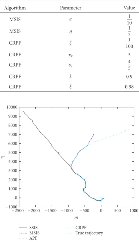
Figure 1shows an example of application of the proposed
al-gorithms to track a maneuvering target during 10 minutes
usingM = 800 particles. It can be observed that the MSIS
and CRPF methods remain locked to the target track during the whole simulation period, and the APF algorithm follows
2The trackers require that these prior densities be available (so that the sensors can initially collect useful data). Obviously, the more a priori un-certainty on the initial target location and speed, the larger the variance of the random variables inx0ands0should be.
Table2: Adjustable parameters in the MSIS and CRPF techniques.
Algorithm Parameter Value
MSIS 101
MSIS η 1
2
CRPF ζ 1
100
CRPF νx 3
CRPF νs 4
5
CRPF λ 0.9
CRPF ξ 0.98
1000 0 1000 2000 3000 4000 5000 6000 7000 8000 9000 10000
m
2500 2000 1500 1000 500 0 500 1000 m
SSIS MSIS APF
CRPF True trajectory
Figure1: Example of tracking a target with the four proposed PF algorithms, all usingM=800 particles andNs=95 sensors, during 10 minutes.
the target trajectory during most of the time, but the SSIS procedure looses the track when a maneuver starts. This is
coherent with the well-known inefficiency of the a priori
im-portance function, which often requires a very large number of particles for adequate performance. It also justifies the ef-fort in developing the alternative algorithms MSIS and CRPF. An instance of a sensor track for the same simulation
ex-periment is presented inFigure 2(upper plot). It is seen that
the true and estimated tracks remain locked (even for the SSIS algorithm, that looses the target but attains good
esti-mates of the sensor locations). In the lower plot ofFigure 2,
we observe how the estimates of the corresponding
log-power converge to the true value,n. Note thatn,tandn ,t
(for the SIS-type and CRPF algorithms, resp.) are, indeed,
1000 0 1000 2000 3000 4000 5000 6000 7000 8000 9000 10000
m
2500 2000 1500 1000 500 0 500 1000 m
Sensor track (SSIS) Estimated (SSIS) Sensor track (MSIS) Estimated (MSIS)
Sensor track (APF) Estimated (APF) Sensor track (CRPF) Estimated (CRPF) SSIS
MSIS, CRPF
APF
(a)
1.8 1.6 1.4 1.2 1 0.8 0.6 0.4 0.2 0
log-po
w
er
(dB)
0 100 200 300 400 500 600
t(s) Estimated log-power (SSIS) Estimated log-power (MSIS) Estimated log-power (APF) Estimated log-power (CRPF) True log-power
(b)
Figure2: (a) Example of tracking a sensor trajectory. (b) Example of estimating the log-power (n) of a communication signal. The algo-rithms employed in the simulation are the SSIS, MSIS, APF, and CRPF techniques, all usingM=800 particles to track the target during 10 minutes. The network consists ofNs=95 sensors.
In order to provide a better characterization of the
rel-ative performance of the different tracking algorithms, we
have carried out extensive simulations to estimate (i) the probability of achieving a correct track during 4 minutes of target motion and (ii) the average absolute deviation both in position and velocity, for correct tracks only, of each one of the algorithms. Since the performance is expected to improve when increasing the number of particles, we have carried out
200 independent simulation trials (each one with a diff
er-ent random trajectory) in which the tracking algorithms use
M = 100 particles, 200 simulations usingM = 200
parti-cles, and another 200 trials withM=400 (600 experiments,
overall). For each group of simulation runs, we have calcu-lated the mean absolute deviation
er t =
1 200
200
k=1
rk,t−rk,t, (48)
whererk,tis the estimated position at timetprovided by the
tracker in the kth simulation and rk,t is the corresponding
true position in the same simulation trial. This error is com-pared with a threshold of 40 m. Correct tracks are those with (1/Tmax)
Tmax
t=0 ert <40 m (Tmax=240 s forTs=1 s). For each
tracker, and each value ofM, we have calculated the
percent-age of correct tracks.
Figure 3shows the results attained by the SSIS, MSIS,
APF, and CRPF algorithms as a function of the number of
particlesM. It can be seen that all techniques have a sound
behavior as they improve their performance with increasing
0 20 40 60 80 100
Cor
re
ct
tr
ack
s
(%
)
100 200 400
No. of particles MSIS
CRPF
APF SSIS
Figure3: Proportion of locked (successful) target tracks versus the number of particles,M, after 4 minutes for the SSIS, MSIS, APF, and CRPF algorithms, all using anNs=95 sensor network.
M, but the CRPF procedure and, particularly, the MSIS
0 5 10 15 20 25 30 35
Ab
so
lu
te
d
ev
ia
ti
o
n
(m
)
0 50 100 150 200
t(s) CRPF
MSIS
APF SSIS
Figure 4: Mean absolute deviation in the position estimated by the PF tracking algorithms (withM =100 particles) versus time (4 minutes). Only successful tracks have been used to compute the mean. The network consisted ofNs=95 sensors.
AssumeC simulation trials have yielded successful results,
and letrk,t andvk,tbe the estimates generated by the tracker
in thekth of these experiments, then the mean absolute
de-viations are
ert =
1
C C
k=1
rk,t−rk,t, evt =
1
C C
k=1
vk,t−vk,t. (49)
Figures4–5ploter
t versus time forM = 100 andM =
400, respectively. It can be seen that the most accurate al-gorithm is the APF technique, which outperforms the more robust CRPF and MSIS techniques. The reason is that the en-hanced robustness of the latter methods is attained at the ex-pense of a larger variance in the generation of new particles, that is, the algorithms explore a larger region when propos-ing new target state points, hence they have a better chance of keeping locked when the target maneuvers but, in general, they yield state estimates which are less accurate than those of the APF.
Finally, Figures6–7show the error signalsev
tforM=100
andM = 400, respectively. The relative performance of the
algorithms is similar to what is obtained forert, and for the
same reasons. It is worth pointing out that, in all Figures4–
7, the CRPF algorithm exhibits a slightly better performance than the MSIS method.
7. DISCUSSION
We have addressed the problem of tracking a maneuvering target that moves over a large 2-dimensional space using a limited-size network of dynamic sensors (with motion ca-pabilities) that produce local binary decisions regarding the
0 5 10 15 20 25 30 35
Ab
so
lu
te
d
ev
ia
ti
o
n
(m
)
0 50 100 150 200
t(s) CRPF
MSIS
APF SSIS
Figure 5: Mean absolute deviation in the position estimated by the PF tracking algorithms (withM = 400 particles) versus time (4 minutes). Only successful tracks have been used to compute the mean. The network consisted ofNs=95 sensors.
0 1 2 3 4 5 6 7 8
A
b
solut
e
de
vi
ation
(m/s)
0 50 100 150 200
t(s) CRPF
MSIS
APF SSIS
Figure6: Mean absolute deviation in the speed estimated by the PF tracking algorithms (withM=100 particles) versus time (4 min-utes). Only successful tracks have been used to compute the mean. The network consisted ofNs=95 sensors.
presence or the absence of the target in a given coverage range. The proposed approach is based on the particle
fil-tering methodology, and we have derived four different