Tektronix, Inc.
TEKTRONI»
4907
Copyright © 1978 by Tektronix, Inc., Beaverton, Oregon. Printed in the United States of America. All rights reserved. Contents of this publication may not be reproduced in any form without permission of Tektronix, Inc.
This instrument, in whole or in part, may be protected by one or more U.S. or foreign patents or patent applications. Information provided on request by Tektronix, Inc., P.O. Box 500, Beaverton, Oregon, 97077.
PRODUCT 4907,4907 Option 30, and 4907 Option 31
This manual supports the following versions of this product: 8010101 and up
MANUAL REVISION STATUS
REV. DATE· DESCRIPTION
INTRODUCTION
SECTION 1
SECTION 2
TABLE OF CONTENTS
STANDARD AND OPTIONAL ACCESSORIES
4907 Accessories
Page
Standard Accessories ... 1-1 Optional Accessories ... 1-1 4907 Option 30 Accessories
Standard Accessories ... 1-1 4907 Option 31 Accessories
Standard Accessories ... 1-2 4907F32 Kit Accessories
Standard Accessories ... 1-2 Components ... 1-2 4907F48 Components ... 1-3 Test Calibration Fixtures ... 1-3
SPECIFICATIONS
4907 Performance Specifications ... 2-1 4907 Physical Specifications ... 2-1 4907 Environmental Specifications ... 2-2 4907 Electrical Specifications ... 2-3 Flexible Disc Drive Specifications ... 2-3 Media Requirements ... 2-4 ROM Pack ... 2-5
I WARNING
I
The remaining portion of this Table of Contents lists servicing instructions that expose personnel to hazardous voltages. These instructions are for qualified service personnel only.
SECTION 3
4907 INSTALLATION GUIDE
INSTALLATION INSTRUCTIONS FOR THE 4907 OPTION 30, AND 4907 OPTION 31
Changing Device Addresses ... 3-1 Changing Line Voltage ... 3-5 Line Cord and Ribbon Cable Installation ... 3-10
Line Cord ... " ... 3-10 Ribbon Cable ... 3-10 GPIB and ROM Pack Installation ... 3-12 Power Up ... 3-t4 4907 (Single Drive) ... 3-14 4907 Option 30 and 4907 Option 31 ... 3-14 Loading the Drive ... 3-14
SECTION 4 PERFORMANCE CHECKS Page
Read/Write Test Program ... 4-1 Program Description ... 4-2 Sample Program Output ... 4-3 Write-Protect Tests ... 4-3
SECTION 5 4907F30 FIELD UPGRADE KIT INSTRUCTIONS
SECTION 6 4907F31 FIELD UPGRADE KIT INSTRUCTIONS
SECTION 7 4907F32 FIELD UPGRADE KIT INSTRUCTIONS
ILLUSTRATIONS
Figure Description Page
Figure Description Page
3-1 2 Card position for 220 V ... 3-8 3-13 Card position for 240 V ... 3-8 3-14 Attaching line cord to rear of cabinet ... 3-10 3-15 Plugging ribbon cable to connector J-1 on auxiliary cabinet ... 3-11 3-16 Connecting GPIB cable to rear of main 4907 cabinet ... 3-12 3-17 Plugging in the ROM pack ... 3-13 3-18 Placing disc in drive ... 3-14 3-19 Closing drive door ... 3-15 4-1 Coveri ng the write-protect hole with tape ... 4-4 5-1 Removing main 4907 cabinet cover ... 5-2 5-2 Connecting ribbon cable to J-8 ... 5-3 5-3 Installing Strain Relief Bracket and clamp assembly ... 5-3 5-4 Securing ribbon cable at rear of main 4907 cabinet. ... 5-4 5-5 Attaching ribbon cable to J-1 ... 5-5 7 -1 4907F32 Field Upgrade Kit components ... 7-2 7-2 Loosening drive clamp ... 7-3 7-3 Removing power switch connectors ... 7-4 7 -4 Removi ng power switch ... 7-4 7-5 Removing front panel ... 7...,5 7-6 Removing screws from drive chassis ... 7-5 7 -7 Sliding drive into chassis ... 7-6 7 -8 Reinstalling drive screws ... 7-6 7-9 Rear view of power switch wiring layout. ... 7-7 7-10 Threading ribbon cable D through grommets in cabinet chassis ... 7-8 7-11 Connecting front panel leads of cable D ... 7-9 7-12 Placing new leads on line filter ... , ... 7-10 7-13 Connecting ribbon cable D to J-11 ... 7-11 7-14 Wire set E in place including a single connector to each drive, two
ground connections, and two leads to the fan ... 7-12 7-15 Installing ribbon cable F ... 7-13 7-16 Installing ribbon cable G ... 7-13
TABLES
Table Description Page
INTRODUCTION
This manual describes the steps necessary to connect the 4907 to the 4051 Graphic System as well as the steps preparatory to operation. Combined, these two instruments with the ROM pack constitute the 4907 File Manager. The 4907 File Manager may be purchased in one of three configurations.
1. The basic 4907 with a single flexible disc drive. 2. The 4907 Option 30 with two flexible disc drives. 3. The 4907 Option 31 with three flexible disc drives.
Section 1 lists the standard and optional accessories for each of the three 4907 configu rations.
Section 2 lists the performance, physical, and electrical specifications for the 4907, the disc drive, and the ROM pack.
Section 3 shows the installation sequences for all three configurations.
Section 4 describes performance checks. These are required to insure that the unit is functional when installed. If hardware problems arise, as indicated by error messages, see the 4907 Service Manual.
Section 5 demonstrates procedures for installing the 4907F30 Field Upgrade Kit. This kit consists of a cabinet with a single flexible disc drive that must be connected to the main 4907 cabinet.
Section 6 demonstrates procedures for installing the 4907F31 Field Upgrade Kit. This kit consists of a cabinet with two flexible disc drives that must be connected to the main 4907 cabinet.
Section 7 demonstrates procedures for installing the 4907F32 Field Upgrade Kit. This kit consists of a single flexible disc drive with all the components necessary for installation into the auxiliary cabinet which is part of the 4907 Option 30. This auxiliary cabinet already contains one flexible disc drive. Installation of this kit fills in the empty side of this cabinet. After installation of the kit, the system configuration is identical to that of the 4907 Option 31.
These procedures should be carried out by a Tektronix technician. If there are questions about system operations, refer to the 4907 File Manager Operator's Manual or the 4907 File Manager Pocket Reference Card. If service questions arise, refer to the 4907 Service Manual.
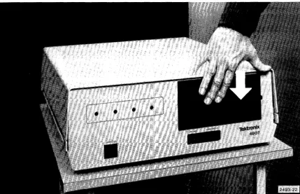
Figure 1-1. 4907 (single drive).
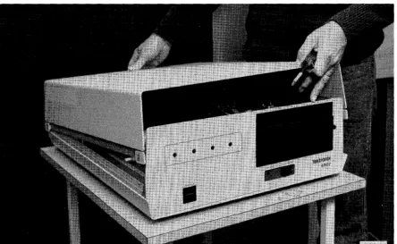
Figure 1-2. 4907 Option 30 (two drives).
Section
1
STANDARD AND OPTIONAL ACCESSORIES
All 4907 File Manager systems come with the standard accessories listed directly below. The systems with Option 30 or Option 31 contain additional standard accessories which are listed under those headings.
4907 ACCESSORIES
Standard Accessories
4907 File Manager Operator's Manual Power Cord
1 Flexible Disc Media Box of Cleaning Pads (10) G PI B Cable 2M
4907 Installation Guide
4907 File Manager Pocket Reference Card 4907 File Manager Label Set
4907 File Manager ROM Pack
Optional Accessories
Box of Flexible Disc Media (10) 4907 Service Manual
G PI B Cable 4M
Flexible Disc Drive Service Manual Alignment Disc
4907 OPTION 30 ACCESSORIES
(Also included in 4907F30 Kits)
Standard Accessories
Power Cord
I ntercon nect Cable Strain Relief Bracket Clamp
1 Flexible Disc Media Box of Cleaning Pads (10) 4907 Installation Guide 4907 File Manager Label Set
STANDARD AND OPTIONAL ACCESSORIES
4907 OPTION 31 ACCESSORIES
(Also included in 4907F31 Kit)
Standard Accessories
Power Cord
Interconnect Cable Strain Relief Bracket Clamp
2 Flexible Disc Media Box of Cleaning Pads (10) 4907 Installation Guide
2 4907 File Manager Label Sets
4907F32 KIT ACCESSORIES
Standard Accessories
1 Flexible Disc Media Box of Cleaning Pads (10) 4907 Installation Guide 4907 File Manager Label Set
Components
6 Attaching Screws Drive Kit
Front Panel Wire Kit
STANDARD AND OPTIONAL ACCESSORIES
4907F48 COMPONENTS (For conversion to 50 Hz)
Belt
Pulley (50 Hz) Set Screw
Fuse 1 A Med Blow
TEST CALIBRATION FIXTURES
Alignment Disc System Test Fixture Test Prom
Section 2
SPECIFICATIONS
4907 PERFORMANCE SPECIFICATIONS
1. Data File Storage Capacity (formatted and accessible by operator) Per Drive (includes
256-byte directory) Per Track
Per Sector
2. GPIB Data Transfer Rate Burst
Sustained 3. Error Rate
Refer to FLEXIBLE DISC DRIVE SPECIFICATIONS.
4907 PHYSICAL SPECIFICATIONS
1 . Di mens ions Height Width Depth
(minus drive door handle projection) 2. Weight
Main Unit
Auxiliary Unit of Option 30 Auxiliary Unit of Option 31
630,528 bytes 8192 bytes
256 bytes
3900 bytes/sec 1300 bytes/sec
7.94 in (20.1 7 em) 20.31 in (51.59 em) 25.25 in (64.14 em)
SPECIFICATIONS
2-2
4907 ENVIRONMENTAL SPECIFICATIONS
1. Operating Environment Ambient Temperature Relative Humidity Maximum Wet Bulb
Maximum Altitude Above Sea Level
2. Storage Environment Ambient Temperature Relative Humidity
Maximum Altitude Above Sea Level Shipping Temperature
3. Shock (nonoperating)
50 degrees F to 1 00 degrees F
(1 0 degrees C to 38 degrees C)
20% to 80%
78 degrees F (25 degrees C)
1 0,000 ft (3048 m)
50 degrees F to 125 degrees F
(10 degrees C to 52 degrees C)
8% to 80%
50,000 ft (15,240 m)
40 degrees F to 125 degrees F (-40 degrees C to 52 degrees C)
Unit will not suffer damage or fail to operate when subjected to three impact shocks of 20 g's
+
in each direction along each main axis. Shock time is 11+
1 ms.4. Vibration
Unit will not suffer damage or fail to operate when subjected to the following vibration for a period of 5 minutes along each main axis.
Nonoperating 5 to 25 Hz at 0.008 in displacement 25 to 55 Hz at 0.004 in displacement Operating 5 to 25 Hz at 0.0014 in displacement 25 to 55 Hz at 0.0007 in displacement
SPECIFICATIONS
4907 ELECTRICAL SPECIFICATIONS
1. AC Power Supply Requirements
A rear panel line voltage selector matches the transformer inputs to four different line voltages. 50 Hz systems can be used by changing the pulley and belt in the disc drives. Table 2-1 shows the allowable line voltages:
Table 2-1
LINE VOLTAGES
Line
Voltage Tolerance
100 Vac 90-110
120 Vac 108-132
220 Vac 198-142
240 Vac 216-264
2. Power Dissipation
Frequency Fuse
2 A Med Blow
50 or 60 Hz 2 A Med Blow
+.5 Hz 1 A Med Blow
1 A Med Blow
115 Vac 200 W maximum
FLEXIBLE DISC DRIVE SPECIFICATIONS
1. Type
Rackmount Flexible Disc Drive, with hard sector (32), write-protect hole detect, and double-density recording.
2. Performance Specifications
Capacity (unformatted) Per Disk
Per Track Transfer Rate Latency (average) Access Time
Track to Track Average Settling Time Head Load Time
6.4 megabits 83.4 kilobits 500 kilobits/sec 83 ms
8 ms 260 ms
SPECIFICATIONS
2-4
3. Physical Specifications Error Rates
Soft Read Errors Hard Read Errors Seek Errors
4. Environmental Specifications
1 per 1 OE9 bits read 1 per 1 OE 1 2 bits read 1 per 10E6 seek operations
Same as 4907 ENVIRONMENTAL SPECIFICATIONS. 5. Safety
The flexible disc drive is listed with Underwriter's Laboratory, Inc. and certified by the Canadian Standards Association.
MEDIA REQUIREMENTS
1. Type
2. Storage Environment Temperature
Humidity 3. Media Lifetime
Passes per track Insertions
@
Double-density compatible
40 degrees F to 1 40 degrees F (5 degrees C to 60 degrees C)
8% to 80%
3.5 x 10E5 >30,000
ROM PACK
1. Dimensions Length Width Depth
2. Weight
3. Environmental Requirements
466in
2.62 in 0.88 in 80z
Same as 4907 ENVIRONMENTAL SPECIFICATIONS. 4. Power Requirements (from 4051)
+5 Vdc 300 rnA
Section 3
INSTALLATION INSTRUCTIONS FOR THE
4907, 4907 OPTION 30, AND 4907
OPTION 31
Confirm that all components and accessories (described in Section 1) that you
ordered have arrived. The following procedures demonstrate how to install your 4907.
CHANGING DEVICE ADDRESSES
The address of any device (drive) in your 4907 may be specified as an integer from 0 to 3. The address depends on the location of the address straps in the base of the drive. The factory-set address strapping for each 4907 configuration is shown below.
4907 (single drive)
4907 Option 30 (two drives) Main cabinet drive
Auxiliary cabinet drive 4907 Option 31 (three drives)
Main cabinet drive
Auxiliary cabinet left hand drive Auxiliary cabinet right hand drive
Device address 0
Device address 0 Device address 1
Device address 0 Device address 1 Device address 2
If an address in one of your devices must be changed, the address strapping must be altered. The following procedure shows how this is done.
INSTALLATION INSTRUCTIONS
WARNING
I
The line cord to the cabinet must be removed to avoid exposure to dangerous voltages.
1. Be sure line cord has been removed.
2. Turn cabinet over and carefully place on a soft cloth.
3. Remove ten bottom screws then lift off base (Figure 3-1). Do not remove feet.
INSTALLATION INSTRUCTIONS
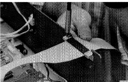
4. Locate factory-set address strapping (Figure 3-2) and change strap to the desired address. See Figures 3-3,3-4,3-5 and 3-6.
Figure 3-2. Location of drive address straps.
Figure 3-3. Setting for device address 0 (OS1).
INSTALLATION INSTRUCTIONS
Figure 3-4. Setting for device address 1 (052).
INSTALLATION INSTRUCTIONS
Figure 3-6. Setting for device address 3* (054).
5. Repeat procedures for additional drives if necessary. 6. Replace base and turn cabinet upright again.
7. Apply the labels with the correct device address to the front of the drives.
CHANGING LINE VOLTAGE
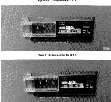
Line voltage in all 4907 cabinets have been factory-set to 100, 120, 220 or 240 volts. The voltage setting for your particular 4907 may be seen through the plastic viewport in the rear of the cabinet. See Figures 3-10 through 3-13. The voltage may be changed by following the procedures shown below.
WARNING
I
The line cord to the cabinet must be removed to avoid exposure to dangerous voltages.
* Note that terminator straps are present only on the drive with the highest address. If your system has only one drive, the terminator straps must be present on that drive. If it contains two drives, the straps must be present on the second drive. If you have a three drive system, they must be present on the third drive.
INSTALLATION INSTRUCTIONS
1. Each 4907 cabinet has a sliding plastic viewport over the line voltage selector located in the rear. Move the viewport to the left (Figure 3-7).
Figure 3-7. Moving viewport to the left.
2. Remove fuse by pulling out lever marked FUSE PULL (Figure 3-8).
INSTALLATION INSTRUCTIONS
3. Remove line voltage selector card using pliers or pointed object (Figure 3-9).
Figure 3-9. Removing line voltage selector card.
4. Reinsert circuit card so that only the line voltage desired may be read after card is reinserted and viewport closed (Figures 3-10,3-11,3-12 and 3-13).
Figure 3-10. Card position for 100 V.
INSTALLATION INSTRUCTIONS
Figure 3-11. Card position for 120
v.
INSTALLATION INSTRUCTIONS
5. Replace fuse. If it is a new fuse, be sure it meets voltage range requirements shown in Table 3-1.
Table 3-1
FUSE SPECIFICATIONS
Voltage Fuse
Voltage Tolerance Frequency Capacity
100 or 120 10% 50 or 60 Hz 2A 220 or 240 10% 50 or 60 Hz 1A
6. Slide viewport back in place and plug in power cord. 7. Repeat procedure on any additional cabinet, if necessary.
NOTE
Changing from 60 to 50 Hz requires the use of
a
different pulley and belt. Contact your Tektronix Service Center.INSTALLATION INSTRUCTIONS
LINE CORD AND RIBBON CABLE INSTALLATION
Line Cord
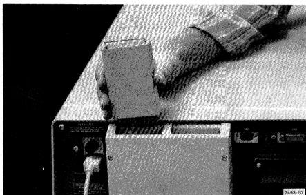
1. Attach end of line cord to rear of cabinet (Figure 3-1 4).
Figure 3-14. Attaching line cord to rear of cabinet.
2. Attach opposite end of line cord to convenient wall socket. 3. Repeat with any additional cabinet.
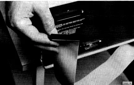
Ribbon Cable
Ribbon cable installation connecting the two 4907 cabinets is necessary ONLY on the 4907 Option 30 and 4907 Option 31. It is not required on the 4907 with the single drive. 1. Place main 4907 cabinet and auxiliary 4907 cabinet in the position in which they will
be operated.
2. Remove tape or rubber band from folded ribbon cable that extends from the rear of the main 4907 cabinet.
INSTALLATION INSTRUCTIONS
Figure 3-15. Plugging ribbon cable to connector J-1 on auxiliary cabinet.
INSTALLATION INSTRUCTIONS
GPIB CABLE AND ROM PACK INSTALLATION
1. Turn off the 4051.
2. Connect the GPIB cable from the rear of the 4051 to the rear of the main 4907 cabinet (Figure 3-16). Use attached screws to secure the connector. If another GPIB cable is already attached, attach the new cable connector over the top of the current cable connector.
Figure 3-16. Connecting GPIB cable to rear of main 4907 cabinet.
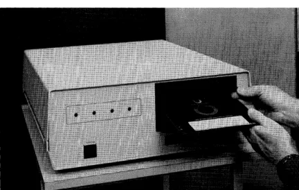
3. Plug the 4907 File Manager ROM pack into any available slot in the 4051 backpack (Figure 3-17) or into a ROM Expander. Be sure the 4051 has been turned off.
INSTALLATION INSTRUCTIONS
Figure 3-17. Plugging in the ROM pack.
The ROM pack may be plugged into any available slot in any 4051E01 ROM EXPANDER. Only one 4051 File Manager ROM pack may be plugged into a single 4051 at the same time. Installing more than one of these ROM packs sets up
a
conflict since each 4907 must havea
GPIB address setting of O. For this same reason a 4051 can support only one 4907.4. The 4907 can now be powered up. See POWER UP.
INSTALLATION INSTRUCTIONS
POWER UP
4907 (Single Drive)
1. Turn on the 4051.
2. Turn on front panel power switch on main 4907 cabinet.
4907 Option 30 and 4907 Option 31
1. Turn on the 4051.
2. Turn on front panel power switch on main 4907 cabinet. 3. Turn on front panel power switch on auxiliary cabinet.
LOADING THE DRIVE
INSTALLATION INSTRUCTIONS
2. Close door (Figure 3-19).
Figure 3-19. Closing drive door.
3. Repeat sequence with additional drives, if necessary.
4. Start operation. (See 4907 File Manager Operator's Manual.)
Section
4
PERFORMANCE CHECKS
Once the 4907 has been interfaced to the 4051 and all necessary installation procedures have been performed, the performance checks must be carried out. This section contains instructions for testing I/O and write-protect performance.
READ/WRITE TEST PROGRAM
The program listed below automatically executes the I/O performance checks on each device (drive) on your 4907 when executed on the 4051. If error messages occur, check ERROR MESSAGES in the 4907 File Manager Operator's Manual. Be sure that all entries are correct and that all preparatory steps described earlier in this manual have been performed.
A sample of the program output and a description of the program operations follow the program listing below.
lee IHtT
119 DIM
R.(200e)~FS(20e)129 CALL
-TIME·~R.130 IF LEH(RS)e THEH 170
140 PRINT "EHTER DATE AND TIME (DD-MOM-YY HH:HM:SS):";
150INPUT
AS169 CALL "SETTIMM,A$
178
PRIHT
"HOW MAN V DEUICES ON YOUR SYSTEM?:".
180 IHPUT H
199 DIM D(H)
299 PPIHT "EHTER DEVICE ADDRESSES:",
219
IHPUT
0
220 FOR 1=1 TO H
238 PRIHT "JJTHIS IS A SAMPLE PROGRAM FOR DEVICE
"JD(I>'"J-248
CALL "UNIT",D(I)
259
CALL "DRES·,O(I)
269
CALL "FORMAT",O(I),"SAMPlE",1,1,"OWHER","PASS",3,3,3,3,J
279
CALL
"DREl",O(I)
280 CREATE "ASCFILE","AU,1,0
290
CREATE "BIHFILE";1,128
309 OPEN "ASCFILE";l,"F",F$
319 PRINT 11:"THIS IS AN ASCII SAMPLE (SEQUENTIAL FILE)"
328 OPEN"BIHFILE";2,"F",Ff
338 WRITE 12,1:"THIS IS A BIHARY SAMPLE (RANDOM FILE)"
348 CALL "REWIND",l
358 INPUT 11:S.
369
PRINT Sf
319 READ '2, 1
:ss
388
PRIHT S'
PERFORMANCE CHECKS
Program Description
100 Initialize. 110
120 130 140
150 Set system clock, if necessary. 160
170
180 Enter the total devices on your system (1,2, or 3). 190
200
210 Enter the device addresses (0 or 0, 1, etc.). 220
230 Print heading. 240 Set unit number.
250 }
260 Format disc. 270
280 Create an ASCII, sequential file. 290 Create a binary, random file
300)
310
Open each file and store message. 320
330
340 Rewind sequential file.
350 )
360
Access fi les and display messages. 370
380
390 Close both fi les. 400
410 End program.
PERFORMANCE CHECKS
Sample Program Output
RUN
ENTER DATE AHD TIME (DD-MOM-VV HH:MM:SS):12-DEC-77
89:31:3.
HOW
MANY
DEVICES OH
YOUR SVSTEM?:1
EHTER DEVICE ADDRESSES:9
THIS IS A SAMPLE PROGRAM FOR DEVICE
e
FORHAT REQUESTED, OK TO
DESTROV DATA
ON DEVICE
91V
THIS IS AN ASCII SAMPLE (SEQUENTIAL
FILE)
THIS
IS A BINARY SAMPLE (RANDOM FILE)
WRITE-PROTECT TESTS
To insure that both the write-protect switch and the write-protect feature on the disc will work, the following procedure should be carried out.
1. Power up the system.
2. Choose the drive to be tested.
3. Turn the write-protect switch OFF. The write-protect indicator light should go off. 4. Load the drive with a formatted disc. Be sure the tape supplied with the disc is
PERFORMANCE CHECKS
4-4
Figure 4-1. Covering the write-protect hole with tape.
5. Execute a CALL "CUSTAT". Be sure to dimension the string variable large enough to contain the device status messages.
6. Call the string variable.
7. The device status message should indicate that no write protection is in effect. 8. Turn ON the write-protect switch for that drive. The write-protect indicator should be
lit.
9. Execute another CALL "CUSTAT" and recall the string variable.
1 O. The message should indicate that write-protection is now in effect for that drive.
PERFORMANCE CHECKS
11. Turn OFF the write-protect switch for that drive. The indicator should go out. 12. Take out the disc and remove the tape over the write-protect hole.
13. Replace the disc in the drive and close the door. The write-protect indicator should go on.
14. Execute another CALL "CUSTAT" and recall the string variable.
1 5. The message should indicate write-protection is in effect for that drive. You have now tested both the write-protect switch and the write-protect feature on the disc.
Section
5
4907F30 FIELD UPGRADE KIT INSTRUCTIONS
The 4907F30 Field Upgrade Kit includes:
1. Single flexible disc drive in a cabinet similar to the main 4907 cabinet. 2. Ribbon cable (interconnect cable).
3. Strain Relief Bracket and clamp assembly. 4. Line cord.
5. One flexible disc. 6. 4907 Installation Guide. 7. Box of cleaning pads (10). 8. 4907 File Manager label kit.
The procedure below describes how to install this kit.
a. Be sure all components listed above have been received. b. Place the 4907F30 cabinet on a flat surface next to the 4907.
WARNING
I
Be sure power has been turned off and line cord has been removed from
cabinet.
c. The new drive may require a different device address. The factory-set address is 1. If a change is necessary, see CHANGING DEVICE ADDRESSES in Section 3.
d. Line voltage may require changing. If a change is necessary see CHANGING LINE VOLTAGE in Section 3.
e. Remove three screws from each side and lift cover from main 4907 cabinet (Figure 5-1).
4907F30 FIELD UPGRADE KIT INSTRUCTIONS
Figure 5-1. Removing main 4907 cabinet cover.
f. Install ribbon cable to connector J-8 on the power supply board (Figure 5-2). Align red stripe with pin 1.
4907F30 FIELD UPGRADE KIT INSTRUCTIONS
Figure 5-2. Connecting ribbon cable to J-8.
Figure 5-3. Installing strain relief cable and clamp assembly.
4907F30 FIELD UPGRADE KIT INSTRUCTIONS
h. Insert ribbon cable through bracket and clamp assembly with red stripe on the left as seen from the rear (Figure 5-4). Tighten clamp.
4907F30 FIELD UPGRADE KIT INSTRUCTIONS
i. Attach free end of ribbon cable to connector J-1 on rear of 4907F30 cabinet (Figure 5-5) with pin 1 to the left as seen from the rear.
Figure 5-5. Attaching ribbon cable to J-1.
j. Replace cover. Attach appropriate device address label to front of drive.
k. Plug one end of line cord into rear of 4907F30 cabinet and the opposite end into a convenient wall socket.
I. The system may now be powered up: 1. Turn on 4051.
2. Turn on front panel switch on main 4907 cabinet. 3. Turn on front panel switch on 4907F30 cabinet.
m. Flexible discs may now be loaded into the drives. See LOADING THE DRIVE in Section 3.
n. Performance checks must be carried out on the new drive. See Section 4.
o. The 4907 with the 4907F30 kit is now ready for operation. See 4907 File Manager. Operator's Manual.
Section 6
4907F31 FIELD UPGRADE KIT INSTRUCTIONS
The 4907F31 Field Upgrade Kit consists of:
1. Two flexible disc drives in a cabinet similar to the main 4907 cabinet. 2. Ribbon cable (interconnect cable).
3. Strain Relief Bracket and clamp assembly. 4. Line cord.
5. Two flexible discs. 6. 4907 Installation Guide. 7. Box of cleaning pads (10).
8. Two 4907 File Manager label sets.
The procedure below describes how to install this kit.
a. Be sure all components listed above have been received. b. Place the 4907F31 cabinet on a flat surface next to the 4907.
WARNING
I
Be sure power has been turned off and line cord has been removed from cabinet.
c. The new drives may require different device addresses. The factory-set address is 1 for the left-hand drive and 2 for the right-hand drive. See CHANGING DEVICE
ADDRESSES in Section 3.
Section
7
4907F32 FIELD UPGRADE KIT INSTRUCTIONS
The 4907F32 Field Upgrade Kit consists of the parts shown in Figure 7-1 and includes: 1. One single flexible disc drive (A).
2. One dual drive front panel (B). 3. Two nylon tie wraps (C). 4. One ribbon cable (D).
5. One double daisy chain wire set (E) to fan, ground, etc. 6. One ribbon cable (F).
7. One ribbon cable (G).
8. Write-protect switch with LED and bezel (H). 9. Unit busy LED with recessed washer (J).
10. 4907 File Manager label set (not shown). 11. Box of cleaning pads (1 O)(not shown). 12. Six attaching screws (not shown). 13. Recessed washer (not shown).
4907F32 FIELD UPGRADE KIT INSTRUCTIONS
Figure 7 -1. Field upgrade kit components.
The procedure below describes how to install this kit.
a. Be sure all components listed above have been received. b. Disconnect ribbon cable from the rear of the 4907F32 cabinet.
WARNING
I
Be sure power has been turned off and line card has been removed from cabinet.
4907F32 FIELD UPGRADE KIT INSTRUCTIONS
e. Loosen clamp holding drive to chassis (Figure 7-2).
f. Turn unit over and place on soft cloth to prevent scratches. Next, remove ten bottom screws and lift off base.
g. Remove power switch connectors (Figure 7-3).
Figure 7-2. Loosening drive clamp.
4907F32 FIELD UPGRADE KIT INSTRUCTIONS
Figure 7 -3. Removing power switch connectors.
4907F32 FIELD UPGRADE KIT INSTRUCTIONS
i. Remove front panel from unit by removing eight nuts (Figure 7-5).
j. Remove four screws from kit drive chassis (Figure 7-6).
Figure 7-5. Removing front panel.
Figure 7 -6. Removing screws from kit drive chassis.
4907F32 FIELD UPGRADE KIT INSTRUCTIONS
k. Slide drive into chassis (Figure 7-7).
I. Reinstall four screws through cabinet chassis (Figure 7-8) plus two side screws.
4907F32 FIELD UPGRADE KIT INSTRUCTIONS
m. Check CHANGING DEVICE ADDRESSES in Section 3 to see what the address setting is on the kit drive. If your current drives are set to 0 and 1, the address on the new drive should be set to 2. If current drive addresses are 1 and 2, the new drive address should be set to 3.
n. Install new front panel.
o. Install power switch and connectors (Figure 7 -9).
TOP
GRAY /WHITE/BROWN
o
o
GRAY /BLACK/BROWNGRAY/WHITE/RED
o
o
GRAY /RED/BLACKRED/BLACK
o
o
BLACK2493-35 Figure 7-9. Rear view of power switch wiring layout.
p. Install new unit busy LED and write-protect switch with LED in front panel. Note that the anode pin on the unit busy LED is indicated by a
"+"
at its base. The cathode side of the write-protect LED is indicated by a flat spot on the side of the LED itself. This flat spot can only be seen if the LED is removed from the write-protect housing.q. Thread front panel ribbon cable (D) through grommets 1, 2 and 3 in cabinet chassis (Figure 7-10).
4907F32 FIELD UPGRADE KIT INSTRUCTIONS
Figure 7-10. Threading ribbon cable D through grommets in cabinet chassis.
r. Cut old tie wraps and secure new ribbon cable (D) to chassis walls and to adjacent wiring with new tie wraps (Figure 7-10).
s. Attach cable D to new front panel LEDs and write-protect switch:
(1) Plug yellow connector into rear of the unit busy LED. Position the plug so the green and white wire is connected to the anode pin (Figure 7-11). (2) Plug orange con.nector into rear of write-protect LED (Figure 7 -11).
Position the plug so the red and white wire is connected to the pin next to the flat side of the LED.
4907F32 FIELD UPGRADE KIT INSTRUCTIONS
Figure 7 -11. Connecting front panel leads of cable D.
4907F32 FIELD UPGRADE KIT INSTRUCTIONS
t. Wire set E must now be attached to the line filter (Figure 7-12).
(1) Thread the end of wire set E with MALCC connectors up into the cabinet chassis from below.
(2) Remove and discard existing MALCC connectors (brown and gray/brown and red) from line filter.
(3) Plug in MALCC connectors on wire set E to line filter: brown and gray to lug C, brown and red to lug E.
4907F32 FIELD UPGRADE KIT INSTRUCTIONS
u. Replace base and turn cabinet right side up.
v. Tighten clamp loosened in step d. This secures both drives to chassis.
w. Plug opposite end of ribbon cable D into J-11 on circuit board (Figure 7-13).
Figure 7-13. Connecting ribbon cable 0 to J-11.
4907F32 FIELD UPGRADE KIT INSTRUCTIONS
x. After feeding ends of wire set E under power supply circuit board, connect as shown in Figure 7-14. Original single drive wire set must first be removed and discarded.
4907F32 FIELD UPGRADE KIT INSTRUCTIONS
y. Install ribbon cable F (Figure 7-15). z. Install ribbon cable G (Figure 7-16).
Figure 7-15. Installing ribbon cable F.
Figure 7 -16. Installing ribbon cable G.
4907F32 FIELD UPGRADE KIT INSTRUCTIONS
aa. Be sure all connections are accurately and securely in place, then reinstall cover.
bb. Return cabinet to operating location. Attach appropriate device address labels to front of drives.
cc. Replace ribbon cable and line cord leading to main 4907 cabinet.
MANUAL CHANGE INFORMP1.TION
CHANGE REFERENCE Cl/378
committed 10
PRODUCT _____
4_9_O_
7 ______ __
070-2493-00 DATE _-..":3:::...--=.1:..:0:.-.-..:.-7.;::..8 _ _ _ _ _
technical excellonce
CHANGE: DESCRIPTION
TEXT CORRECTIONS
Page 3-10
Change Step 2 and Step 3 under "Ribbon Cable" to the following:
2. Plug one end of the ribbon cable with the ground braid and exterior
ground strips in Jl of the auxiliary cabinet and the other end of
the ribbon cable in Jl of the main cabinet.
Pin 1 of the cable is positioned to the left on both cabinets. This
will position the ground braid out and the cable will be looped over
at the top cabinet. Refer to F~gure 3-15.
3. Install the ground clamps on each of the cabinets so that they trap
the ribbon cable between the back of the cabinet and the clamp at the
exterior ground strip on the ribbon cable. Tighten the screws securely,
but do not overtighten. Refer to Figure 3-15.
Page 3-11
Replace Figure 3-15 as shown below:
---~---~
AUXILlAIW , CASINET
Figure 3-15. Plugging ribbon cable to connector J-1 on main and auxiliary cabinets.
PRODUCT _ _
4_9_0_7 _ _ _ _ _ _
CHANGE REFERENCE _ _ _Cl_I_3_7_8 ___
DATE _ _ _3_-_l_0_-_7_8 _ _
_
CHANGE: DESCRIPTION
Page 5-1
Change Step
2and Step
3to the following:
2. Ribbon cable (shielded interconnect cable).
3. Ribbon cable with rear panelmount.
Add Step
9,Step
10,and Step
11as follows:
9.
Clamp.
10.
Screws
6-32
x.375.
110 Kemnuts
6-32.
Page
5-3
Replac~
Figure
5-3 as shown below:
Page
5-2
Change Step g to the following:
Mount the plug on the back of the
4907 cabinet with pin one
~othe left
as seen from the rear (Figure
5-3).
! REAR
INEL
I
4907
PRODUCT _ _ _ _ _ _ _ _ _ _ CHANGEREFERENCE ___ C_l_I_37_8 ______ _ DATE ____ 3_-l_0_-_7_8_. ____ __
CHANGE: DESCRIPTION
Page 5-4
Change Part h. and Part i. to the following:
h. Plug one end of the shielded ribbon table into the connector J-l on
the rear panel of the main 4907 cabinet and plug the other end of the
cable into connector J-l on the rear panel of the auxiliary 4907F30
cabinet. Pin 1 on the jack is on the left of both cabinets.
i. Install the ground clamps on each cabinet. Be sure the ground clamps
on both cabinets trap the ribbon cable between the back of the cabinet
and the clamp at the exterior ground strip of the ribbon cablee
Replace Figure 5-4 as shown below:
AUXILIARY
, CABINET
MAIN
CABINET
RIBBON CABLE
Figure 5-4. Securing ribbon cable to rear of main and auxiliary cabinets.