WYSE
I I I ICopyright Notice
Disclaimer
Trademarks
© 1985, Wyse Technology. All rights reserved.
This guide and the firmware described in it are copyrighted by Wyse
Technology. You may not reproduce, transmit, transcribe, store in a retrieval system, or translate into any language or computer language, in any form or by any means, electronic, mechanical, magnetic, optical, chemical, manual, or otherwise, any part of this publication without the express written permission of Wyse Technology.
Wyse Technology makes no representations or warranties regarding the contents of this document. We reserve the right to revise this document or make changes to the specifications of the product described within it at any time without notice and without obligation to notify any person of such revision or change.
WYSE® is a registered trademark of Wyse Technology WY_85™ is a trademark of Wyse Technology
Centronics® is a registered trademark of Centronics Data Computer Corporation
IBM® is a registered trademark of International Business Machines Dysan® is a registered trademark of Dysan Corporation
Hayes Smartmodem® is a registered trademark of Hayes Microcomputer Products, Inc
VT52T. , VTlOQ'·, and VT20Q'· are trademarks of Digital Equipment
Corporation
Overview
By reading this guide you will be able to quickly install and set up your WY -85 terminal.
The companion guide, the WY-85 Programmer's Guide, tells you how to write programs to utilize the terminal's features. To order the WY-85 Programmer's
Guide simply fill out the business reply card at the back of this guide and mail it to us.
This manual contains four chapters and three appendices:
Chapter 1 contains installation procedures that include unpacking the terminal and attaching a computer, printer, and modem.
Chapter 2 discusses the setup mode. You may have to enter the setup mode to change the terminal's parameters so that it can communicate with a computer, printer, or modem. This chapter also contains instructions to program the function keys.
Chapter 3 describes the capabilities of the terminal including the keyboard (description of each key), multikey commands, communication modes, and special features (i.e., scrolling speed).
Chapter 4 discusses simple troubleshooting procedures for problems such as a locked keyboard or blank screen.
Appendix A contains the terminal specifications.
Appendix B provides connector pin assignments.
Table of Contents
1 Installation
Getting Ready
Connecting the Terminal to a Computer Connecting a Modem
Connecting a Printer Turning on the Terminal Adjusting the Terminal Completing Installation
2 Configuring the Terminal
Entering Setup ModeChanging the Setup Parameters Leaving Setup Mode
3 Terminal Capabilities
Keyboard Description Additional Features Operating Modes4 Troubleshooting
Introduction
Symptoms and Solutions
Appendices
A Terminal Specifications B Connector Pin Assignments C Recognized Command Sequences
Index
1-2 1-3 1-7 1-8 1-9 1-10 1-11
2-2
2-4
2-27
3-2 3-10 3-11
4-2
4-2
A-I B-1 C-l
List of Tables
2-1 Setup Levels 2-2 Directory Functions
2-3 Display One Setup Parameters 2-4 Display Two Setup Parameters 2-5 General One Setup Parameters 2-6 General Two Setup Parameters
2-7 Communications One Setup Parameters
2-8 Communications Two Setup Parameters
2-9 Printer One Setup Parameters 2-10 Printer Two Setup Parameters 2-11 Keyboard One Setup Parameters 2-12 Keyboard Two Setup Parameters 2-13 Send Setup Parameters
3-1 Main Keypad Functions 3-2 Editing Keypad Functions 3-3 PF and Function Key Functions
B-1 COMM Port Configuration B-2 PR Port Configuration B-3 20 rnA Port Configuration B-4 Typical Modem Pin Assignments B-5 Sample Printer Connections
2-4 2-7 2-8 2-9 2-10 2-12 2-13 2-15 2-17 2-19 2-20 2-21 2-22
3-3 3-5 3-7
1
Installing the Terminal
This chapter provides detailed illustrated installation instructions for your terminal.
Getting Ready
Unpacking and inspecting the terminal
Connecting the Terminal to a Computer
Connecting the terminal cables to a computer
Connecting a Modem
Connecting a modem to your terminal
Connecting a Printer
Connecting a printer to your terminal
Turning on the Terminal
Describes self-test and status messages
Adjusting the Terminal
Adjusting the position and brightness of the terminal
Completing Installation
Discusses internal setup requirements
1-2
1-3
1-7
1-8
1-9
1-10
Getting Ready
As you unpack your terminal, make sure you received everything shown below. If anything is missing or visibly damaged, contact the dealer from whom you purchased the terminal.Power Cord
The keyboard cable and the power cord come with your terminal. You'll also need an RS-232C interface cable (fitted with a female 25-pin connector on one end) to connect the terminal to your computer. To connect a serial-type printer directly to your terminal, you'll need a second RS-232C interface cable. These cables can be purchased from your dealer.
The terminal should be located in an area
• Near a grounded, three-pronged power outlet.
Connecting the Terminal
to a Computer
To connect the terminal to your computer
1. Press the bottom half of the power switch on the front of the terminal's base to the off position.
2. Plug the coiled cable into the socket labeled KYBD on the back of the terminal and into the keyboard.
3. Plug the slotted (female) end of the power cord into the three-pronged connector on the back of the terminal.
Power Cord
4. The power requirements shown on the label on the back of the terminal should match the voltage in your area. If not, return your terminal to the factory (or contact your distributor) to change the setting.
---nmm::-5. Plug the pronged end of the power cord into a three-pronged (in the U.S.), grounded power outlet (or use an adapter for a two-pronged outlet). However, if you only have a two-pronged power outlet, be sure to ground the outlet by attaching the adapter's pigtail to the faceplate screw.
6. Locate your computer's interface cable. It should be an EIA-standard RS-232C or RS-423 cable with a female 25-pin connector on at least one end. If you're connecting a computer configured for current loop (such as a DEC), the interface cable will be an 8-pin, male 20mA connector (MATE-N-LOK) .
• Note-Not every computer has the same configuration on its RS-232C
port. If the pin connector on the RS-232C cable isn't configured to meet the requirements of the computer and the terminal, they won't work as expected (or may not work at all). The pin assignments of the terminal's ports are listed in Appendix B. If the connection pins differ, you should contact the systems analyst for your computer to see about
Connecting a Modem
You can connect a modem to the terminal so it communicates over telephone lines with another computer .• Note-If the pin assignments required by your modem differ from those needed by your computer, you'll need an RS-232C interface cable especially configured for your modem. Your modem may have its own cable. Refer to your modem's reference manual for details.
1. Attach the female end of the 25-pin RS-232C interface cable to the COMM port on the back of the terminal.
Terminal COMM Port
2. Attach the other end of the cable to your modem's RS-232C connector.
3. Follow the instructions in your modem's manual to connect the modem to your telephone.
4. With an Vs-inch, flat-blade screwdriver, tighten the screws on both sides of each connector to secure the interface.
Connecting a Printer
If your software supports a printer connected to a terminal, you can connect a serial printer directly to the terminal. You'll need an RS-232C interface cable with a 9-pin, D-shaped female connector on one end.1. Plug the printer interface cable into the PR port on the back of the terminal.
2. With an \Is-inch, flat-blade screwdriver, tighten the screws on both sides of each connector until secure.
3. Attach the other end of the interface cable to the RS-232C port on the printer .
Turning on the Terminal
After the terminal is properly installed, turn it on by pressing the top half of the terminal's power switch. Listen for an immediate beep indicating that it has received power.Whenever you turn the terminal on, it automatically runs a five-second self-test. If the terminal has recently been on and the cathode ray tube (CRT) is warm, the screen flashes several display patterns as the self-test runs.
If the terminal encounters a problem during the self-test, a beep sounds and an error code appears in the bottom right-hand corner of the screen. You can't operate the terminal if certain error message are shown; it may need to be serviced by a qualified technician .
• Note-If you see an X or Y in the bottom right corner of the screen, see the Troubleshooting chapter.
To reset the terminal so that it will rerun its self-test, press the SHIFT key, CTRL key, and SETUP (F3) key simultaneously.
When the cursor is in the upper left corner of the screen, the terminal has passed all of its tests and is ready for operation.
The next thing to appear on the screen is the message line. LINE, LOCL, ECHO, or BLCK appear at the top left part of the screen. Later you may see
Adjusting the Terminal
Adjust your terminal so that the center of the screen is slightly below your eye level. Swivel the screen sideways and up and down until you find the most comfortable angle.If you want the keyboard tilted slightly, turn it over and pull out the hinged bars. Typing will be more comfortable if the keyboard is at or below your elbow height.
2
Configuring the Terminal
This chapter discusses the setup mode, which includes the keyboard, communication, printer, and send levels.
Entering Setup Mode 2-2
Describes the setup mode and how to enter it
Changing the Setup Parameters 2-4
Describes the setup directory and its function; and each setup level
Leaving Setup Mode 2-27
Introduction
Entering Setup Mode
The terminal and computer must have a common language to communicate. This language is determined by a set of variables called parameters. You can change the values of your terminal's parameters in the setup mode to enable the terminal to communicate with many manufacturers' computers.
The way a terminal's parameters are set make up its configuration. The configuration of your terminal and computer (or other device) must match.
Your terminal has a set of default values. Since these default values may not exactly match the device you want to attach, you may need to change some of these values.
In setup mode, you can also change optional parameters, such as the number of columns displayed on the screen or your cursor attributes, as well as program a set of user-defined function keys to perform desired functions.
Enter setup mode by pressing the SETUP (F3) key. During setup mode, the cursor temporarily disappears, but reappears when the terminal is in its normal mode. The information you enter remains frozen on the screen and cannot be altered .
... Caution-Do not enter setup mode while data is being transmitted between the terminal and the computer. The terminal cannot receive data during setup mode.
A row of boxes (called fields) appear at the top of the screen in setup mode. Each field defines the function of a special key. The fields on the bottom of the screen contain text. These fields make up the setup line and display the parameters you can define for the terminal. See the following figure.
The highlighted field on the setup line is the active field, or the field whose values you can change. Activate desired fields by pressing the. or ~ cursor key.
Changing the Setup Parameters
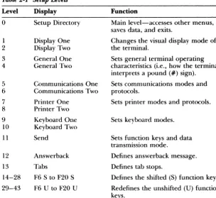
Table 2-1 Setup Levels
Level Display Function
0 Setup Directory Main level-accesses other menus, saves data, and exits.
1 Display One Changes the visual display mode of 2 Display Two the terminal.
3 General One Sets general terminal operating 4 General Two characteristics (i.e., how the terminal
interprets a pound (#) sign).
5 Communications One Sets communications modes and 6 Communications Two protocols.
7
Printer One Sets printer modes and protocols. 8 Printer Two9 Keyboard One Sets keyboard modes.
10 Keyboard Two
11 Send Sets function keys and data transmission mode.
12 Answerback Defines answerback message.
13 Tabs Defines tab stops.
14-28 F6 S to F20 S Defines the shifted (8) function keys.
29-43 F6 U to F20 U Redefines the unshifted (U) function keys.
The first time setup mode is entered, default values appear. Depending on your requirements, you'll probably need to change some of these values.
Consult the user's manual for your computer, modem, and/or printer to determine these device-dependent requirements. Fill in the table below for a record of your device requirements.
Computer Printer Modem Other
Baud rate
Data bits
Parity type
Handshaking protocol
Stop bits
The following sections describe each setup level, the parameters you can access through them, and the selections available for each parameter.
The Setup Directory (Level 0)
You begin with the setup directory each time you enter setup mode. From this directory you can move to any of the other levels, save changes, reset the terminal's parameters to its default values, or exit setup mode.
Press the SETUP key (F3) to enter setup mode and display the setup directory.
Press the ~ or • key to highlight a parameter. Press the spacebar or ENTER key to cycle through the possible values of your selected parameter. The choice displayed is the currently active parameter. To return all parameters to their default values, press the ENTER key while you're in the main directory with the Default field highlighted.
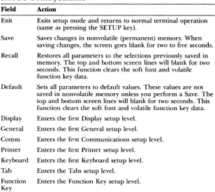
Table 2-2 lists the setup directory fields and describes the actions they perform.
Table 2·2 Directory Functions
Field Exit
Save
Recall
Default
Display
General
Comm
Printer
Keyboard
Tab
Function Key
Action
Exits setup mode and returns to normal terminal operation (same as pressing the SETUP key).
Saves changes in nonvolatile (permanent) memory. When saving changes, the screen goes blank for two to five seconds.
Restores all parameters to the selections previously saved in memory. The top and bottom screen lines will blank for two seconds. This function clears the soft font and volatile function key data.
Sets all parameters to default values. These values are not saved in nonvolatile memory unless you perform a Save. The top and bottom screen lines will blank for two seconds. This function clears the soft font and volatile function key data.
Enters the first Display setup level.
Enters the first General setup level.
Enters the first Communications setup level.
Enters the first Printer setup level.
Enters the first Keyboard setup level.
Enters the Tabs setup level.
You can enter key setup levels by selecting commands from the setup line. You can access unlisted (hidden) levels from nearby levels by pressing the. or • cursor key. To enter the Answerback level, for example, you could select Tab from the setup directory, then press the. key once.
The Display Setup (Levels One and Two)
The Display setup levels control the visual display of the terminal.
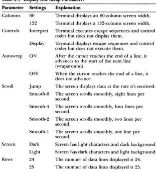
Table 2-3 Display One Setup Parameters
Parameter
Columns
Controls
Autowrap
Scroll
Screen
Rows
Settings
80
132
Interpret
Display
ON
Explanation
Terminal displays an 80-column screen width.
Terminal displays a I 32-column screen width.
Terminal executes escape sequences and control codes but does not display them.
Terminal displays escape sequences and control codes but does not execute them.
After the cursor reaches the end of a line, it advances to the start of the next line (wraparound).
OFF When the cursor reaches the end of a line, it does not advance.
Jump The screen displays data at the rate it's received.
Smooth-8 The screen scrolls smoothly, eight lines per second.
Smooth-4 The screen scrolls smoothly, four lines per second.
Smooth-2 The screen scrolls smoothly, two lines per second.
Smooth-l The screen scrolls smoothly, one line per second.
Dark
Light
24
25
Screen has light characters and dark background.
Screen has dark characters and light background.
The number of data lines displayed is 24.
Table 2-4 describes the second Display setup parameters and their possible settings, with default settings listed first.
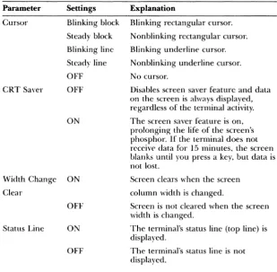
Table 2.4 Display Two Setup Parameters
Parameter
Cursor
CRT Saver
Settings Explanation
Blinking block Blinking rectangular cursor.
Steady block Nonblinking rectangular cursor.
Blinking line
Steady line
OFF
OFF
ON
Blinking underline cursor.
Nonblinking underline cursor.
No cursor.
Disables screen saver feature and data on the screen is always displayed, regardless of the terminal activity.
The screen saver feature is on, prolonging the life of the screen's phosphor. If the terminal does not receive data for 15 minutes, the screen blanks until you press a key, but data is not lost.
Width Change ON
Clear
Screen clears when the screen
column width is changed.
OFF
Status Line ON
OFF
Screen is not cleared when the screen width is changed.
The terminal's status line (top line) is displayed.
The General Setup (Levels Three and Four)
Parameters in the General levels determine general operating characteristics of the terminal, such as how the terminal interprets a pound sign (#).
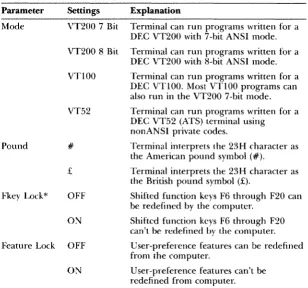
Table 2-5 describes the parameters that can be set from the first General setup level and the settings available for each, with default settings listed first.
Table
2·5
General One Setup ParametersParameter
Mode
Pound
Settings
VT200 7 Bit
Explanation
Terminal can run programs written for a DEC VT200 with 7-hit ANSI mode.
VT200 8 Bit Terminal can run programs written for a DEC VT200 with 8-bit ANSI mode.
VT100 Terminal can run programs written for a
DEC VT100. Most VT100 programs can also run in the VT200 7-bit mode.
VT52 Terminal can run programs written for a DEC VT52 (ATS) terminal using
nonANSI private codes.
#
£
Terminal interprets the 23H character as the American pound symbol (#).
Terminal interprets the 23H character as the British pound symbol (£).
Fkey Lock* OFF Shifted function keys F6 through F20 can
be redefined by the computer.
ON
Feature Lock OFF
ON
Shifted function keys F6 through F20 can't be redefined by the computer.
User-preference features can be redefined from the computer.
User-preference features can't be redefined from computer.
Table 2-5 Continued
Parameter Settings Explanation
Newline OFF Pressing the RETURN key sends only a carriage
return (CR) code. A !inefeed (LF) is not interpreted as a CR LF.
Local
ON Pressing RETURN sends a CR LF combination.
OFF
LF is interpreted as CR LF. CR is interpreted as CR.
Terminal is in conversational mode; it processes all data from the computer normally.
ON Terminal is in local mode; it ignores all data from the computer and processes all keyboard data locally.
The affected user-preference features are key repeat, scroll speed, screen color (reverse/normal), tab stops, and keyboard lock. Select OFF when your software controls these features.
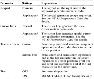
Table 2·6 General Two Setup Parameters
Parameter Settings Explanation
Keypad Numeric The keypad on the right side of the
keyboard generates numeric codes.
Application* The keypad generates escape sequences. See the WY·85 Programmer's Guide for details.
Cursor Keys Normal The cursor keys generate the usual
cursor motion commands.
Application* The cursor keys generate special cursor key application commands. See the
WY-85 Prograrmner:~ Guide for details.
Transfer Tt'fm Cursor Print (to printer) and send (to computer) operations end with the character at the cursor position.
Test
Screen End
OFF
ON
Print screen and send screen operations end at the last character on the screen regardless of cursor position; print line and send line operations end at the last character on the cursor line.
For normal operation.
DO NOT SELECT; for factory use only.
*This feature cannot be saved in nonvolatile memory. Power-on status is always normal.
The Communications Setup (Levels Five and Six)
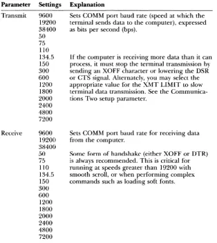
Table 2-7 describes the parameters you can set at the first Communications level and the optional settings for each, with default settings listed first.
Table 2·7 Communications One Setup Parameters
Parameter Settings Explanation
Transmit 9600 Sets COMM port baud rate (speed at which the
Receive
19200 terminal sends data to the computer), expressed 38400 as bits per second (bps).
50
75
110 134.5150
300 6001200
18002000
2400 4800 7200 9600 19200 38400 5075
1 JO134.5
150 300 600 1200 1800If the computer is receiving more data than it can process, it must stop the terminal transmission by
sending an XOFF character or lowering the DSR or CTS signal. Alternately, you may select the appropriate value for the XMT LIMIT to slow terminal data transmission. See the Communica-tions Two setup parameter.
Sets COI\HvI port baud rate for receiving data from the computer.
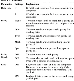
Table 2-7 Continued
Parameter Settings Explanation
Data Bits 8 COMM port transmits 8-bit data words to the computer.
7 COMM port transmits 7-bit data words to the computer.
Parity None Terminal doesn't add or check for a parity bit when it communicates with the computer or a modem.
Parity Check
Echo
Odd
Even
Mark
Space
OFF
ON
OFF
Terminal sends and expects odd parity for sending data.
Terminal sends and expects even parity for sending data.
Terminal sends and expects a high (mark) parity bit.
Terminal sends and expects a low (space) parity bit.
Terminal does not check parity.
Terminal checks parity and indicates bad parity bytes with a reverse question mark.
Keyboard data is sent only to the computer. Data can be seen on the screen only if the computer echoes it back to the terminal (full duplex).
Table 2-8 describes the parameters available at the second Communications setup level and their possible settings, with default settings listed first.
Table 2-8 Communications Two Setup Parameters
Parameter Settings Explanation
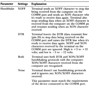
Handshake XOFF
DTR
Both
None
Terminal sends an XOFF character to stop data being received from the computer on the COMM port and sends an XON character when it's ready to receive data again. Terminal also stops sending data when an XOFF character is received from the computer on the COMM port and resumes sending when an XON character is received.
Terminal lowers the DTR (data transmit) line (pin 20) to stop data being received on the COMM port and raises the DTR line when it's ready to receive data again. XOFF and XON characters received by the terminal on the COMM port are ignored. High is +3 to + 12 volts; and low is -3 to -12 volts.
Terminal uses both DTR and XON/XOFF handshaking protocols with the computer. XON/XOFF characters received from the computer are recognized.
Terminal doesn't use handshaking protocols and it ignores any XON/XOFF characters received.
Table 2-8 Continued
Parameter
Stop Bits
Port
Disconnect
Settings
2
EIA Data
Explanation
Terminal sends to the computer and expects one bit to signal the end of a data character. Terminal sends to the computer and expects two bits to signal the end of a data character.
Terminal transmits and receives data through the RS-232C port; only standard data pins are active.
EIA Modem Terminal transmits and receives data through the RS-232C port; modem signals are active on the proper pins. See Appendix B for pin definitions.
20mA Terminal transmits and receives data through the 20mA current loop port.
2 sec
60 ms
Terminal disconnects if received signal line detection (RSLD) is lost for two seconds (pin 8).
Terminal disconnects if RSLD is lost for 60 milliseconds (United Kingdom only).
XMT Limit None Terminal transmits all data, except
reprogrammed key data, as fast as possible.
150 cps
60 cps
Terminal transmits all data at a maximum rate of 150 characters per second (cps), regardless of the baud rate.
The Printer Setup (Levels Seven and Eight)
The Printer setup levels should be set to match the parameters of your attached printer. These levels also determine the parameter associated with the printer port and printing functions. Tables 2-9 and 2-10 describe the parameters that can be set from the first Printer and second Printer setup levels. The defaults for each are listed first.
Table 2-9 Printer One Setup Parameters
Parameter Settings Explanation
Speed 4800 Sets PR port baud rate for transmitting and
receiving data. 7200
9600 19200 110 134.5 150 300 600 1200 1800 2000 2400 3600
The printer can stop transmission from the terminal by sending an XOFF character or by lowering the DSR signal on the PR port.
Generally, when printer receive mode is enabled on the printer, it sends an XOFF character and/or lowers the DTR signal (as defined ill the printer Handshake parameter) if it isn't ready to receive data from the PR port.
Data Bits 8 PR port transmits to the computer and expects only 8-bit data words.
Parity
7 PR port transmits to the computer and expects
only 7-bit data words.
None Terminal doesn't send or expect a parity bit on the PR port.
Table
2-9
ContinuedParameter Settings
Parity Even
Mark
Space
Stop Bits
2
Handshake XOFF
DTR
Both
None
Terminator None
FF
Explanation
Terminal sends and expects an even parity bit on the PR port.
Terminal sends and expects a high (mark) parity bit on the PR port.
Terminal sends and expects a low (space) parity bit on the PR port.
Terminal sends one stop bit to the printer, signaling the end of a data character.
Terminal sends two stop bits to the printer, signaling the end of a data character.
When the buffer is almost full, the terminal sends an XOFF character to the printer; when the buffer is almost empty, the terminal sends an XON character.
When the buffer is almost full, the terminal lowers the DTR signal (pin 20); when it's almost empty, the terminal raises the DTR signal.
Terminal uses both DTR and XON!XOFF handshaking protocols.
Terminal uses no handshaking when communicating with the printer. Not recommended.
Terminal doesn't send a termination character after it completes a print screen operation.
Table 2-10 Printer Two Setup Parameters
Parameter Settings Explanation
Print Region .' Full Screen Sends the entire screen during a print screen operation.
Print Data
Print Mode
PR Receive
Scroll Region Sends scroll region during a print screen operation.
ASCII Prints onlv ASCII characters. Other
character; are replaced with underscores or the closest ASCII character.
Draw/ASCII Prints only ASCII and line drawing characters. Other characters are replaced with underscores or the closest ASCII character.
All
Normal
Auto print
Controller
ON
PrillLs all characters.
The printer prints data only in response to print line and screen commands.
In response to a LF, FF, VT, or autowrap data prints as the cursor moves to the next line (copy print command).
All data is sent from the COMM port to the printer without being displayed (transparent print).
All data from the printer (PR) port (except XON and XOFF characters) is ignored.
The Keyboard Setup (Levels Nine and Ten)
Keyboard parameters determine how the keyboard responds. Many of these parameters, such as keyclick, are a matter of preference. Others, such as the rate at which data generated by function keys is sent, is determined by your computer's requirements. Tables 2-11 and 2-12 describe the parameters that can be set from the Keyboard levels.
Table
2·11
Keyboard One Setup ParametersParameter Settings Explanation
Lock Caps LOCK key is a caps lock key. Alphabetic keys generate only uppercase characters.
Shift LOCK key is a shift lock key. Alphabetic keys generate uppercase characters and numeric/ symbol keys generate only shifted characters.
Rev LOCK is a reverse shift key, reversing the sense of the SHIFT key as it pertains to all alphabetic keys.
Keyrepeat ON All keys repeat when held down for more than half a second.
OFF No keys repeat when held down.
Keyclick ON A click sounds each time a key is pressed or repeated.
OFF No click sounds when a key is pressed or repeated.
Margin Bell OFF No bell sounds when the cursor moves within eight columns of the right margin.
ON The bell sounds when the cursor moves within eight columns of the right margin.
Warning Bell ON Received BEL (CTRL G) characters sound the bell.
OFF Received BEL characters don't sound the bell.
Break ON Break sends a break signal for 250 ms on the XMT line.
Table 2·12 Keyboard Two Setup Parameters
Parameter Settings Explanation
Answerback ON The answerback message is sent during a
communication reconnect, and at power-on.
Compose
OFF
'ON
1'\0 answerback message is sem during a communication reconnect or at power-on.
To define the answerback message, see "The Answerback Setup Level" in this chapter.
The COMPOSE CHARACTER key is enabled.
OFF The COMPOSE CHARACTER key is
disabled.
<Z1
DEL/CAN The unshifted<Z1
key generates a "deletecharacter"; shifted, it generates a "cancel character."
BS/DEL The unshifled
<Z1
key generates a"backspace character"; shifted, it generates a "delete character."
The Send Setup (Level
11)Table 2·13 Send Setup Parameters
Parameters
FKeys
Fkey Xmt
Send Send Area Settings Remote Local 60 cps 150 cps Unlim All Erase Full Screen Scroll Region
Send Term None
FF
Explanation
The code programmed into keys F6 through F20 (unshifted) is sent to the computer, unless the terminal is in local mode.
The code programmed into keys F6 through F20 (unshifted) is processed locally by the terminal.
Data generated by programmed function keys is transmitted at a maximum rate of 60 characters per second (cps), regardless of baud rate.
Programmed function key data is transmitted at a maximum rate of 150 cps.
Programmed function key data is transmitted as fast as possible.
Send line and screen commands transmit all characters.
Send commands transmit only characters specified as erasable; a record separator character is transmitted in place of one or more contiguous nonerasable character(s).
Send screen operations transmit the entire screen.
Send screen operations transmit only active scroll region.
No character is sent after a send screen operation.
The Answerback Setup (Level
12)
You can ask the terminal to send an answerback message to the computer before it can log on or access an application. The answerback message may act like a password and can be sent automatically by the terminal, or the message can be sent manually from the keyboard. For purposes of confidentiality, you can conceal this password.
The answerback message is transmitted to the computer in the following cases:
• The computer receives the ENQ character and the terminal is in VT200, VT100, or VT52 mode .
• You press the BREAK (F5) key with the CTRL and SHIFT keys.
To define the answerback message:
l. Press the SETUP key (F3) to enter setup mode and display the setup directory.
2. Press the ~ key until the Tabs field in the bottom line is highlighted.
3. Press the spacebar or ENTER key to enter the Tabs setup level.
4. Press the. key to enter the Answerback setup level.
5. Press the
<XI
key to clear the old message, then type the new message (up to 30 characters).To conceal the answerback message and keep it from being displayed press the REMOVE key at any time on this level. The answerback message is replaced by the word <CONCEALED> and cannot be redisplayed unless you redefine it.
The Tabs Setup (Level
13)You can clear and set tab stops anywhere within the margins from the Tabs setup level:
1. Press the SETUP key (F3) to display the setup directory.
2. Highlight the Tab field and press the spacebar or ENTER key to enter the Tabs setup level.
3. With the cursor on the tab line, position tab stops where you want.
• To move the cursor across the line, press the ~ or ... cursor keys.
• To clear all tab stops, press the
<ZI
key.• To clear an individual tab stop at the cursor position, press the spacebar.
• To set an individual tab stop at the cursor position, press the T key.
• To alternately set or clear a tab at the cursor position, press the ENTER key.
• To restore all the default tabs, press the TAB key.
The Function Key Setup (Levels 14-43)
The keyboard's function keys can transmit multiple characters with one keystroke. F6 through F20, including HELP and DO, are programmable; you can assign them any number of possible functions.
If the unshifted function keys have never been programmed, they transmit a set of standard default codes. The WY-85 Programmer's Guide lists those codes. The shifted function keys are initially blank and perform no function until programmed.
~ Caution-Applications that require default values for the unshifted function keys may not run properly if you redefine these keys.
To program a function key:
• Note - If the Key Lock parameter (first Keyboard level) is set to On, you won't be
able to program the shifted function keys.
2. Highlight Function Keys on the setup line and press the spacebar or ENTER key to enter the first Function Key setup level (level 14).
3. Press the ~ key until you reach the level containing your key; or press the function key you want to change. Shifted function keys (F6 S through F20 S) are programmed in levels 14 through 28. Unshifted function keys (F6 U through F20 U) are in levels 29 through 43.
4. The normal bottom setup line is replaced with a highlighted field, such as
I
F1 5To program the key, just type the characters you want transmitted. You may enter as many characters as there is space in the field, which is generally 80 characters in 80-column mode and 127 characters in the 132-column mode.
To enter a carriage return (CR) code in the sequence, hold down the CTRL key while pressing M (or RETURN). A carriage return counts as one character.
If you make a mistake, press the
Q]
key to erase the entire line or press the .... key to erase one character.5. To display other function key levels, press the A and ~ keys, or press the desired function key.
6. To stop programming function keys and display the setup directory, press SETUP (F3) or another function key.
For example, to program F7 (shifted) to send the code sequence DIR<CR> (directory-carriage return), follow these steps:
1. Press the SETUP key (F3).
Leaving
Setup Mode
To display the disk's directory, you can just press F7 (or whatever key you've defined), instead of having to type in the command
DIR<CR>
• Note -Your computer's response to a transmitted code depends on the program you're running at the time. Different programs may interpret the same code differently.
You can define the function keys as a group to act as either local or remote keys. Local keys are processed at the terminal only; remote keys transmit characters to the computer first. See "Keyboard Two Setup Level" in this chapter.
There are 400 characters available for all function keys. The first 134
characters are saved in nonvolatile memory; characters beyond that are erased when you turn off the terminal. Those 134 characters saved are indicated by full-intensity characters in the function key definition field; those characters erased will appear dim.
The 134 nonvolatile characters are allocated to the first function keys in sequential order (F6 S through F20 S, then F6 U through F20 U). If you redefine the programs of higher priority keys, be aware that you may alter the volatility of characters in lower priority keys. For more information see the
WY-85 Programmer~ Guide.
When you exit setup mode, you have the choice of saving or not saving the changes you made. Changes you make but don't save still take effect after you exit setup mode but only stay in effect until you turn the terminal off. To exit setup mode and save changes:
1. Press SETUP (F3) to display the setup directory.
2. Select the Save function and press the spacebar or ENTER key. The screen blanks for two to five seconds.
3. You automatically exit setup mode after a save operation.
To exit the setup mode without saving changes:
1. Press the SETUP key (F3).
2. Select EXIT and press the spacebar or ENTER key, or press the SETUP key again.
3
Terminal Capabilities
This chapter describes the basic capabilities of the terminal: the keyboard, multikey commands, communication modes, and special features.
Keyboard Description
Describes the main keyboard, numeric keypad, and function keys
Additional Features
Discusses scrolling speed, keyclick, graphics characters, compose characters, and monitor mode
Operating Modes
Describes communication between computer and terminal: full duplex, half duplex, and block modes
3-2
3-lO
Keyboard Description
The keyboard consists of a main keypad, an editing keypad, an auxiliary keypad, and a row of 20 function keys. The main keypad contains the standard alphanumeric keys of letters, numbers, and symbols usually associated with those on a typewriter keyboard. The editing keypad contains cursor movement keys and special editing keys. The auxiliary keypad contains four PF keys and a standard numeric keypad, which is helpful in heavily numeric text such as that used in accounting records. Function keys F 1 through F5 perform predefined local functions. Function keys F6 through F20 either generate predefined codes or they may be reprogrammed to generate user-defined codes (see Chapter 2).Table 3-1 describes the special keys of the main keypad. Table 3-2 describes the special keys of the editing keypad. Table 3-3 describes the PF keys and the function keys.
Keys are either local or remote. Local keys cause specific functions to occur, generally without communication to the computer. Remote keys send data to the computer (if the terminal is in full-duplex online mode). This data is interpreted by the computer, which then performs a specific action based on this data.
EJI=rtll: ... 1
fS*il~~
Table 3·1 Main Keypad Functions
Key Description
COMPOSE CHARACTER
CTRL
LOCK
In VT200 mode, this allows you to compose
multinational (European) characters not found on the keyboard. In VT100 or VT52 modes, pressing this key simultaneously with another key causes that character to be modified as with the META key found on other terminals. See "Composing Characters" later in this chapter.
Pressed simultaneously with another key, CTRL generates a control code. Pressing CTRL by itself has no effect. Normally undisplayed, control codes cause the terminal and! or program to take special action. Press CTRL with SHIFT and SETUP (F3) simultaneously to reset the terminal.
Initiates caps lock, shift lock, or reverse shift mode, depending on the selection made for the Lock setup parameter (first Keyboard level, Chapter 2).
When Lock is set to CAPS, all alphabetic keys typed appear as uppercase; number and symbol kt"ys are unaffected.
When Lock is set to SHIFT, letters are uppercase, and numeric and symbol keys show their shifted character.
When Lock is set to REV, the sense of the SHIFT key is reversed as it applies to alphabetic keys. In other words, pressing an alphabetic key simultaneously with the SHIFT keY, when the terminal is in the reverse lock mode, generates a lowercase character. Pressing an alphabetic key with the SHIFT key up generates uppercase characters. Number and symbol keys are unaffected.
Table 3-1 Continued
Key
RETURN
SHIFT
Space Bar
TAB
(g]
(Delete)Description
Sends a carriage return (CR) code to the computer. The computer's interpretation of this code depends on its program and the Newline parameter (first General setup level, Chapter 2). H Newline is on, a linefeed (LF) code is also sent. This key indicates the end of a data entry to the computer.
When pressed simultaneously with an alphanumeric key, shows the uppercase letter or the upper character shown on the number and symbol keys. Each of the two SHIFT keys function the saine. Pressing the SHIFT key by itself has no effect. Press SHIFT, CTRL and SETUP (F3) simultaneously to reset the terminal.
Pressing the space bar creates the space (SP) character.
Sends the horizontal tab (HT) character. This generally causes the cursor to move to the next tab stop.
•
fable J·2 Editing Keypad Functions
Key
Cursor Keys
FIND
INSERT HERE
NEXT SCREEN
Description
Pressing one of these keys moves the cursor in the direction indicated by the arrow on the key. With the CTRL key held down: Pressing the" selects a slower scrolling rate; pressing the ... selects a faster scrolling rate; pressing the .. toggles the status line on and off; and pressing the ... toggles the monitor and control execution disable modes on and off.
Sends the Find command to the computer. The effect of this command depends on the application program being run.
In all modes except block mode, pressing this key sends the Insert Here command to the computer. The effect of this command depends on the application program being run. In the block mode, pressing this key toggles the terminal in and out of the insert mode. With the insert mode 011, characters are added to the left of the cursor as you type, moving the cursor to the right. With the insert mode off, you type over existing characters.
In all modes except block mode, pressing this key sends the Next Screen command to the computer. The effect of this command depends on the application program being run.
Table }·2 Continued
Key
PREV SCREEN
REMOVE
SELECT
Description
In all modes except block mode, this key sends the Previous Screen command to the computer. The effect of this command depends on the application program being run. In block mode, or with the CTRL key held down, it homes the cursor and clears the screen. If the CTRL key is held down while this key is pressed, the screen is cleared and the cursor is sent to the horne position, regardless of whether the tenninal is in block mode.
In all modes except hlock mode, this key sends the remove command to the computer. The effect of this command depends on the application program being run.
In block mode, this key deletes the character at the cursor position, moving the characters on the right one position left.
Sends the Select command to the computer. The effect of this command depends on the application program being run.
Table
3·3PF and Function
Key
Functions
Key Function Description
Fl HOLD IfXON/XOFF or DTR handshaking is enabled,
F2
F3
F4
F.I)
SCREEN the appropriate handshake with the computer is performed. The Fl key toggles data processing on and off. This key is the equivalent of the NO SCROLL key on a VT100 or WY-75 terminal.
PRINT SCREEN
RESET/ SETUP
SEND/ BLOCK
BREAK
Pressed without CTRL and SHIFT, this key transmits the contents of the screen (from the cursor position to the end of the screen, including protected characters) to the printer. Pressed with crRL or SHIFr, it toggles in and out of auto print mode.
Pressed without CTRL and SHIrr, it puts the terminal in setup mode, displaying the setup directory and setup status line (see Chapter 2). Pressed with CTRL and SHIFT, it performs a hard reset, resetting the terminal to its power-up state. Pressed with only SHIrr, it performs a soft reset, resetting all terminal modes and error conditions.
Pressed with SHIrr, it transmits the cursor line. Pressed without SHUt, it toggles the terminal in and out of block mode.
Table J-J Ctnltinued
Key Function Description
F6-F20 (shifted)
F6 (unshifted)
F7 (unshifted)
F8 (unshifted)
F9 (unshifted)
FlO (unshifted)
.1'11 ESC (unshifted)
No effect.
F6 through F20, both unshifted and shifted, may be redefined to generate different codes. The following descriptions only apply to F6 through F20 as they are set at the factory, prior to any redefinitions.
In VT52 and VflOO modes, F6 has no effect. In the VT200 mode, this key sends the F6 command to the computer. The effect of this command depends on the application program being run.
In VT52 and VT100 modes, F7 has no effect. In the VT200 mode, this key sends the F7 command to the computer. The effect of this command depends on the application program being run.
In VT52 and VT100 modes, F8 has no effect. In the VT200 mode, this key sends the F8 command to the computer. The effect of this command depends on the application program being run.
In VT52 and VT100 modes, F9 has no effect. In the VT200 mode, this key sends the F9 command to the computer. The effect of this command depends on the application program being run.
In VT52 and VT100 modes, FlO has no effect. In the VT200 mode, this key sends the FlO command
to the computer. The effect of this command depends on the application program being run.
In VT52 and VT100 modes, this key sends the escape character (ESC). Some keys pressed after the Fil ESC key send escape sequences to the computer.
,
•
Table 3-3 Continued
Key Function
F12 BS
(unshifted)
FI3 LF
(unshifted)
Fl4 HOME
(unshifted) HELP (unshifted)
DO
(unshifted) F17-F19 (unshifted)PI" 1 through PH
Description
In VT52 and VT100 modes, this key sends the backspace (BS) character. In VT200 mode. this key sends the F12 command. The effect of this command depends on the application program being run.
In VT52 and VT100 modes, this key sends the !incfeed (LF) character. In VT200 mode, this key sends the }<'13 command. The effect of this command depends on the application program being run.
In VT52 and VT100 modes, this key sends the Home command to the computer, which causes the cursor to move to the top left corner of the screen. In VT200 mode, this kev sends the FI4 command. The effect of this comm~nd depends on the application program being run.
In VT52 and VT 1 00 modes, this kev has no effect. In VT200 mode. this key sends the Help command to the computer. The effect of this command depends on the application program being run.
In VT52 and VT100 modes, this key has no effect. In VT200 mode, this key sends the Do command to the computer. The effect of this command depends on the application program being run.
In the VT52 and VT100 modes, these keys have no effect. In the VT200 mode, these keys send the F17, F18, or FIg commands to the computer. The effect of these commands depends on the application program being run. In the VT100 and VT52 modes, these keys have no effect.
Additional Features
Scrolling Speed
You can set the general scrolling speed with the Scroll parameter (first Display setup level, see Chapter 2). In addition, you can temporarily alter scrolling speed by pressing CTRL and .. to speed up scrolling, and SHIFT with CTRL and ~ to slow down scrolling. This procedure alters the value of the Scroll parameter, but does not save the change in nonvolatile memory.
Keyclick
The keyboard has an optional keydick feature that makes a muted beep each time you press a key. Switch this feature on and off by setting the Keydick parameter (Keyboard one setup level). You can also switch it on and off by pressing CTRL and ENTER. This procedure alters the values of the Keydick parameter but does not save the change in nonvolatile memory.
Graphics Characters
The terminal has several special graphics character sets in addition to its standard characters. However, you can use these additional character sets only with a graphics program that was specially written for them. See the WY-85
Programmer's Guide for details.
Compose Characters
In addition to the standard ASCII character set, you can compose up to 81 multinational (European) characters not found on the keyboard when you are in VT200 7-bit or 8-bit modes. The WY-85 Programmer's Guide lists the compose sequences you can type to create new characters.
To compose a new character:
l. Press COMPOSE CHARACTER. COMP appears on the status line at the top of the screen.
2. Type the keys required to create the desired character (in the order indicated). Each compose sequence consists of two characters. For example, /' creates a raised and centered dot (').
operating Modes
Monitor Mode
You may want to inspect the code characters being sent from the computer. If
the terminal is in monitor mode, these code characters appear on the screen with the normal letters. The computer doesn't act on these codes during monitor mode.
To enter monitor mode, press CTRL with the ... key, or change the Controls parameter (Display one setup level) to Display. Unless the Status Line parameter (Display two setup level) is set to off, an asterisk (*) appears next to the communication mode label on the status line. This indicates that the terminal is in monitor mode.
To exit monitor mode, press CTRL with the ... key again, and the asterisk disappears .
• Note -If the terminal is also in insert mode, an asterisk appears in place of the INS label on the status line.
The terminal provides three operating modes:
• Setup
• Online
• Local
The setup mode is only selectable from the keyboard. This mode allows you to configure the terminal or to check the previously set configuration (see Chapter 2).
HALF DUPLEX
FULL DUPLEX
SCREEN
I
DISPLAY PROCESSOR
BLOCK
LOCAL
Half-Duplex Mode
_ FROM KEYBOARD . . - __ - TO/FROM COMPUTER
---1
COMPUTERBLOCK TRANSMISSION
---1
COMPUTERFull-Duplex Mode
In the online full-duplex communication mode, data entered at the keyboard is sent to the computer and data received from the computer is shown on the screen. In general, this is the normal operating mode. In this mode, LINE is
displayed in the status line.
Block Mode
In the online block communication mode, data entered at the keyboard is only displayed on the terminal screen, until you decide to send the block of data to the computer or to the printer. In this mode, data is sent to the computer by pressing the SEND key, or it can be sent directly to the printer by pressing the PRINT SCREEN key. Data received by the terminal from the computer can occur at any time and will be displayed when received. When this mode is selected, BLCK is displayed in the terminal status line.
Local Mode
4
Troubleshooting
This chapter discusses simple troubleshooting procedures.
Introduction
Symptoms and Solutions
Contains symptoms and possible solutions for various terminal problems
4-2
Introduction
Symptoms and Solutions
For certain problems, the terminal may seem to malfunction when the problem is actually something you can fix yourself. The problem may be the wrong setup value, a loose cable connection, or incorrect pin connections on an interface cable. Before you place a service call, please refer to the solutions listed in this chapter .
• Warning-We are NOT suggesting that you try to fix internal problems. Don't
open the terminal case unless you are a qualified service technician. When the case is open, dangerous voltages are exposed, even after the power has been turned off.
This section contains symptoms and possible solutions to problems you may encounter with your terminal. The symptom is shown in bold and suggested solutions follow.
The terminal doesn't beep when turned on .
.. Caution -The following procedure exposes you to potentially hazardous shock if
you don't unplug the power cable.
1. Turn off the power switch and unplug the power cable.
4. Reinsert the fuse assembly in the rear panel. While pushing on the fuse assembly with the screwdriver, turn it clockwise about one-half turn. Don't force it.
5. Plug in the power cord and turn on the terminal.
Terminal beeps after turned on, but you can't see the cursor.
1. Turn the brightness thumbwheel all the way down (clockwise). See the following illustration.
2. Check the cursor field in the setup mode (Display level two) to make sure the cursor is not set to Off.
The screen goes blank while the terminal is on.
This is a normal condition when the CRT saver parameter is on. You can turn the CRT saver off in the setup mode. After 15 minutes of inactivity, the display disappears but the data is not lost. Press any key to bring back the display (SHIFT will bring back the display without altering it).
The screen doesn't respond when you press a key.
1. If WAIT appears in the terminal message line your program has locked the keyboard. To unlock it, press SETUP with SHIFT.
2. Make sure the keyboard cable connection is good.
The computer doesn't respond when you type on the keyboard.
1. Check the interface cable connections. Is the computer interface cable connected to the COMM port? Does it have the correct connector pin assignments (see Appendix B)?
2. Make sure the status line displays LINE. If it does not turn the block mode off by pressing F4. To turn LOCL off, you must enter the setup mode, General level one. Also check the COMM port baud rate, data bit, handshake, stop bit, and parity bit selections; they should all match your computer.
When the terminal is turned on, an X or Y displays in the bottom right-hand corner of the screen.
Hold down the SETUP key to exit self-test. If the error code continues, turn the terminal off and then on again.
When the terminal is turned on, 0, 1, 2, 3, P, or Z appears in the bottom right-hand corner of the screen.
The terminal needs to be serviced by a qualified technician.
Nonsense characters (garbage) appear on the screen.
1. Match the COMM port baud rate setup parameter in the setup mode with your computer's baud rate.
2. Check the pin connections of the computer interface cable (see Appendix B).
Characters become garbled as they appear on the screen.
Make sure the selection for the stop bit, parity, and data bit setup parameters match the requirements of your computer.
Screen
Display Format
Character Formation
Character Set
Displayed Character Sets
Cursor Control
Cursor Attributes
Communications
Operating Modes
Online Communication Modes
Word Structure
Parity
Handshake Protocol
Maximum Baud Rates
Video Attributes
Keyboard
Appendix A -Specifications
Size: 14 inches measured diagonally. Attributes: P138 green, phosphor.
26 lines (one terminal status line, 24 or 25 data display lines, zero or one label line/system message line); 80 or 132 columns (user selectable).
80-column: 7 X 9 matrix, 10 x 10 cell. 132-column: 7 X 9 matrix, 9 x 10 cell. US ASCII
512 characters (94 displayable ASCII characters, 72 control code symbols, 94 special graphics characters, 94 multinational supplement fonts, 32 graphic characters, 126 soft programmable characters).
Home, up, down, left, right, tab, and carriage return.
Block/line; blinking/steady; on/off.
One DB-25 EIA RS-423 (RS-232C compatible) interface; one 20mA passive current loop interface; and one DB-9 auxiliary printer interface.
Setup, online, and local.
Block, half duplex, and full duplex.
7 or 8 data bits; 1 or 2 stop bits.
Odd, even, mark, none, or space.
XON/XOFF, DTR, both, or none.
COMM Port: 38,400
PR Port: 19,200
20mA Port: 38,400
Normal, dim, bold, blink, blank, underline and reverse (combinable).
Power Requirements
115 volts AC, 60 Hz; 230 volts AC, 50 Hz.Weight
Net weight 31 pounds.Dimensions
Height Width Depthin em in em in em
AppenalX D
-LUTtlteCtur
Pin Assignments
Table B-1 COMM Port Configuration (DTE-Data Terminal Equipment)
Pin Signal Mnemonic Description
Shield Ground PGND Ground to which cable should
be connected.
2 Transmit Data TXD (Output) Transmits serial data
characters. Held low during idle. Data is only sent when DSR, CTS, and DCD are high if modem control mode is enabled. Held high for 1/4 second during a break.
3 Receive Data RXD (Input) Receives serial data
characters.
4 Request Lo Send RTS (Output) Lowered for 2
seconds if the shifted Break key is pressed or if modem control mode is enabled and DCD or DSR is low (60 ms or 2 sec).
5 Clear to Send CTS (Input) If modem control
mode is enabled, data is sent by the terminal when this line and DCD are high. Ignored othenvise.
6 Data Set Ready DSR (Input) If modem control
mode is enabled, data is only sent by the terminal when this line, CTS, and DCD are high. Ignored otherwise.
,.,
Signal Ground SGND Common ground reference
I
Table R·J Continued
Pin Signal Mnemonic Description
8 Data Carrier DCDor (Input) If modem control Detect (Receive RLSD mode is enabled, data is only Signal Detect) sent by the terminal when this
line, DSR, and CTS are high. Ignored otherwise.
12 Speed Indicator SPDI (Input) If modem control mode is enabled, a high level on this line causes the terminal to transmit and receive data at the 1200 baud regardless of the speed selected in setup.
20 Data Terminal DTR (Output) When DTR
Ready handshake is enabled, this line is lowered when the terminal is not ready to receive any more data.
Table B-2 PR Port Configuration
Pin Signal Mnemonic Description
Shield Ground PGND Ground to which cable
shield should be connected.
C) Transmit Data TXD (Output) Transmits serial
...
data characters. Held low during idle. Data is only sent when DSR is high.
3 Receive Data RXD (Input) Receives serial
data characters.
4 Request to Send RTS (Output) This signal is
held high when the terminal is powered on.
S Data Terminal Ready DTR (Output) This signal is
lowered in bidirectional print mode if the DTR handshake is enabled and the terminal is not ready to receive data.
6 Data Set Ready DSR (Input) When this signal
is low, data is not sent out the printer port. If
this signal has not been high since terminal power-up or reset, and printer DTR handshake is enabled in setup mode, print commands are ignored.
7 Signal Ground SGND Common ground
Table B-J 20mA Port Pin Assignments
Pin Signal
1
2
3
5
7
8
Table B-4
Terminal
(DTE)
2
3
7
20
-12 volt
Negative transmit
Negative receive
Positive transmit
Positive receive
Ground
Typical Modem Pin Assignments
Hayes Smartmodem
1200 (DeE)
I
2
3
7
20
We recommend that pins 6 and 8 be disconnected, since they are modem protocols that may "lock up" the terminal.
Table B·5 Sample Printer Connection
9·Pin Male PR Port
Signal (DTE)
Printer (DTE) Transmit Data 2 ~ 3
Receive Data 3 ...
---2
Request to Send 4 ---~~ 5
Clear to Send 5 - - - 6 to 8
Data Set Ready
Signal Ground
6 • 11
7 - - - 7
The pin numbers are
9-Pln Male PR Port 25-Pln Male COMM Port
5 13
0 0 0 0 0 0 0 0 0 0 0 0 0 0 0 0 0 0 0 0 0 0 0 0 0
6 9 14 25
Signal Receive Data
Transmit Data
Clear to Send
Data Set Ready to Data Carrier Detect
Busy
Signal Ground
8-Pln Female 20mA Port
cfc)o
00 0 0
0C5P
Appena'lX
L"
-l(ecogn'lzea
Command Sequences
Command
Controlling Functional Modes* Lock keyboard
Unlock keyboard Monitor mode on** Monitor mode off Insert mode on Insert mode off Local echo off Local echo on
Control execution off** Control execution on
Transmit through cursor position Transmit to end of line or
end of display New line mode on New line mode off Cursor keys send
application-dependent codes Cursor keys send cursor
movement codes VT52 mode on 132-column display 80-column display Smooth scrolling on Jump scrolling on
Reverse screen video on Normal screen video on Line 1 is top of scrolling region Line 1 is top of display area Autowrap on
Sequence
CSI 2 h CSI21 CSI3 h CSI31 CSI4 h CSI41 CSI 12 h CSl 12 I CSI 13 h CSI 13 I
CSI 16 h
CSI 16 I
CSI 20 h
CSI 20 I
CSI ?l h
CSI ?1 I
CSI ?2 I CSI ?3 h CSI ?3 I CSI ?4 h CSI ?41 CSI ?5 h CSI ?51 CSI ?6 h
CSI ?61 CSI
?7
hMnemonic KAM KAM CRM CRM IRM IRM SRM SRM FEAM FEAM TTM TIM LNM LNM DECCKM DECCKM DECANM DECCOLM DECCOLM DECSCLM DECSCLM DECSCNM DECSCNM DECOM DECOM DECAWM
*
j\.jole than one mode, but les, than 17, may be set with one sequence by entenng multiple numel ic paramct.·rs separated by semi