Volume 2009, Article ID 692861,13pages doi:10.1155/2009/692861
Research Article
A Novel Approach to the Design of Oversampling Low-Delay
Complex-Modulated Filter Bank Pairs
Thomas Kurbiel (EURASIP Member), Heinz G. G¨ockler (EURASIP Member),
and Daniel Alfsmann (EURASIP Member)
Digital Signal Processing Group, Ruhr-Universit¨at Bochum, 44780 Bochum, Germany
Correspondence should be addressed to Thomas Kurbiel,[email protected]
Received 15 December 2008; Revised 5 June 2009; Accepted 9 September 2009
Recommended by Sven Nordholm
In this contribution we present a method to design prototype filters of oversampling uniform complex-modulated FIR filter bank pairs. Especially, we present a noniterative two-step procedure: (i) design of analysis prototype filter with minimum group delay and approximately linear-phase frequency response in the passband and the transition band and (ii) Design of synthesis prototype filter such that the filter bank pairs distortion function approximates a linear-phase allpass function. Both aliasing and imaging are controlled by introducing sophisticated stopband constraints in both steps. Moreover, we investigate the delay properties of oversampling uniform complex-modulated FIR filter bank pairs in order to achieve the lowest possible filter bank delay. An illustrative design example demonstrates the potential of the design approach.
Copyright © 2009 Thomas Kurbiel et al. This is an open access article distributed under the Creative Commons Attribution License, which permits unrestricted use, distribution, and reproduction in any medium, provided the original work is properly cited.
1. Introduction
A digital filter bank pair (FBP) is represented by a cascade connection of an analysis filter bank (AFB) for signal decomposition and a synthesis filter bank (SFB) for signal reconstruction. In this contribution, we are exclusively interested in FBP that are most efficient in terms of (i) low power consumption calling forminimum computational loadand a modular structure (minimum control overhead), and (ii) low overall ASFB signal (group) delay. The former property is most important if the FBP is part of mobile equipment with tight energy constraints, most pronounced in hearing aids (HAs) [1], while the latter requirement must, for instance, be considered in two-way communication systems or HA, where the totalgroup delayof the FBP shall not exceed 5–8 milliseconds [2, 3] to allow for sufficient
margin for extensive subband signal processing.
The above computational constraints are best accounted for by using uniform, maximally decimating (critically-sampling),complex-modulated(DFT)polyphaseFB applying FIR filters, where all individual frequency responses of the AFB or SFB are frequency-shifted versions of that of the correspondingprototype lowpass filters, respectively, [4–6].
As it is well known, critical sampling in FBP gives rise to severe aliasing in case of low-order (prototype) filters with overlapping frequency responses which, in general, can be compensated for by proper matching of the AFB and SFB (prototype) filters [5,6]. In contrast, we are interested in FBP that call for extensive subband signal manipulation, where aliasing compensation approaches cannot be used. As a result, the design of FBP considered in this contribution calls for moderatelyoversampled subband signals. Thus, nonlinear distortion due to aliasing and imaging can exclusively be controlled by adequate stopband rejection of the respective (prototype) filters. As an example, stopband magnitude constraints for FBP in HA are derived in [7].
When considering linear-phase (LP) FIR filters for the prototype design, the above stringent group delay require-ments are best met, if the filter lengths are as small as possible [8]. Essentially the same applies to low-delay FIR filter designs [9].
delay can always be obtained that ranges below the group delay of a corresponding LP FIR filter. However, the absolute minimum value of the passband group delay was of no concern. In contrast, for instance, Lang [14] has shown that his algorithms for the constrained design of digital filters with arbitrary magnitude and phase responses have the potential to achieve a considerable reduction of group delay as compared to LP FIR filters, even for high-order FIR filters. Moreover, several solutions to the problem of low-delay filter banks have been suggested in literature. In [15], an iterative method for the design of oversampling DFT filter banks has been proposed, which allows for controlling the distortion function for each frequency and jointly minimizes aliasing and imaging. The demand for low group delay particularly of the AFB prototype filters has not been asked for explicitly. Based on the algorithm [15] the approach [16] introduces additional constraints to the delay and phase responses. Noncritical decimation has also been suggested in [17], where both filter bank delay aspects and magnitude deviations of the distortion function have not especially been taken into consideration. In [18] the problems of aliasing effect and amplitude distortion are studied. Prototype filters which are optimised with respect to those properties are designed and their performances are compared. Moreover, the effect of the number of subbands, the oversampling factors, and the length of the prototype filter are also studied. Using the multicriteria formulation, all Pareto optimums are sought via the nonlinear programming technique. In [19] a hybrid optimization method is proposed to find the Pareto optimums of this highly nonlinear problem. Furthermore it is shown that Kaiser and Dolph-Chebyshev windows give the best overall performance with or without oversampling.
From a filter bank system theoretic point of view, we pursue three objectives, representing steps towards the design ofoversampling uniform complex-modulated(FFT) FIR filter bank pairs (FBPs) allowing for extensive subband signal manipulation. We restrict ourselves tointeger oversampling factorsas defined by
O= I
M ∈N, O>1 (1)
in order not to constrain the applicability of polyphase
prototype filters in any form [4,6], where I represents the number of FB channels andM∈Nthe common decimation or interpolation factor of the FBP, respectively.
(1) In Section 2 being related to the first objective of this paper, we begin with a system-theoretic description and analysis of oversampling I-channel complex-modulated FIR filter bank pairs without subband signal manipulation, which supplements and extends the results reported in [16]. In particular, we investigate the properties of thedistortion function
[5,6], the overall single-input single-output (SISO) transfer function of the filter bank pair that ideally approximates a linear-phase allpass function. We show that both the magnitude and the group delay
of the FBP distortion function are periodic versus frequency. Furthermore, the group delay of the FBP is investigated in detail.
(2) For a first design step (cf. Section 3), we introduce a novel procedure for theconstrained designof low-delay narrow-band FIR prototype filters for over-sampling complex-modulated filter banks with an approximately linear-phase frequency response in the passband and the transition bands. As the objective function to be minimised we adopt a particular representation of the group delay [20], while the stopband magnitude specifications of the prototype filter, as derived in [7], serve as constraints to control subband signal aliasing or imaging, respectively. In the first design step this procedure is used either
for the design of the SFB or the AFB prototype filter.
(3) For the second and final design step (cf.Section 4), we use the deviation of the FBP distortion function from unity as the objective function. To this end, the AFB (or SFB) FIR prototype filter is designed subject to the stopband magnitude constraints, as given by [7], while the SFB (or AFB) prototype filter is fixed to the design obtained in the previous step. By this procedure the AFB and SFB prototype filters’
magnitude responses are matched in the passbands and the transition bands without further consid-eration of the overall FBP group delay, aiming at minimum, possibly differing AFB and SFB prototype filter orders.
To illustrate the results and the potential of the design procedure, we present a design example inSection 5. Finally,
inSection 6we draw some conclusions.
2. Oversampling Complex-Modulated
FIR Filter Bank Pairs
We begin with the introduction of our filter bank notation and a system-theoretic description and analysis of uniform oversamplingI-channel complex-modulated FIR filter bank pairs (FBP) without subband signal manipulation, the principle of which is shown in Figure 1. In particular, we investigate the properties of the distortion function [5,
6], which is required to approximate a linear-phase allpass
function.
2.1. Distortion Function. For a uniform oversampling complex-modulatedI-channel FBP the AFB und SFB filters, respectively, are derived from common prototype filters [5,6]:
Hl(zi)=H
ziWIl
, l=0,. . .,I−1,
Gl(zi)=G
ziWIl
, l=0,. . .,I−1.
X(zi) H0(zi) M X0(zsn) M G0(zi)
Hl(zi)
Xl(zsn)
M Gl(zi) M
HI−1(zi) M
XI−1(zsn)
M GI−1(zi) Y(zi) .
. .
. . .
. . .
. . .
. . .
. . .
. . .
. . .
Figure1: Uniform oversampling filter bank pair, oversampling factorO=I/M∈N.
Both prototype filters arereal-valuedFIR filters represented by their causal transfer functions:
H(zi)=
Nh−1
n=0
h(n)·zi−n=cTh(zi)·h, (3)
G(zi)=
Ng−1
n=0
g(n)·z−n
i =cTg(zi)·g, (4)
where the vectors
h=[h(0),h(1),. . .,h(Nh−1)]T∈RNh,
g=g(0),g(1),. . .,gNg−1 T
∈RNg
(5)
contain Nh or Ng coefficients of the impulse response, respectively, and the vectors
ch(zi)=
1,zi−1,z−2i ,. . .,z −(Nh−1) i
T ,
cg(zi)=
1,z−1i ,z−2i ,. . .,z −(Ng−1) i
T (6)
the associated delays.
The input signal x(n) ↔zT X(zi) in Figure 1is simulta-neously passed through all AFB channel filtersHl(zi), l = 0,. . .,I−1 and subsequently downsampled by a factor ofM, yielding
Xl(zsn)= 1 M
M−1
k=0
Hl
z1/M
sn WMk
Xz1/M
sn WMk
,
l=0, 1,. . .,I−1,
(7)
using the alias component representation [5,6], andWM =
e−j2π/M. In the SFB, theM-fold upsampled subband signals
Xl(zMi )=Xl(zsn) are combined to form thez-domain output signal representation [6]:
Y(zi)=
I−1
l=0
Gl(zi)Xl
zM
i
. (8)
Inserting the upsampled form of (7) into (8), withzsn=zMi we obtain
Y(zi)=
I−1
l=0
Gl(zi) ⎡ ⎣ 1
M
M−1
k=0
Hl
ziWMk
XziWMk
⎤ ⎦
= 1 M
M−1
k=0
XziWMk
⎡ ⎣I−1
l=0
Hl
ziWMk
Gl(zi) ⎤ ⎦.
(9)
Obviously the output signal representationY(zi) depends on allMmodulation componentsX(ziWMk),k= 0,. . .,M−1,
of the input signal. All these components are filtered by the compound term Il=0−1Hl(ziWMk)Gl(zi) and eventually combined. The transfer function of the zeroth (k = 0) modulation component is generally denoted as the distortion function [5,6]:
Fdist(zi)= 1 M
⎡ ⎣I−1
l=0
Hl(zi)Gl(zi) ⎤
⎦. (10)
In our approach this distortion function determines the properties of the FBP almost exclusively, since aliasing and imaging is assumed to be negligible as a result of sufficiently high AFB and SFB prototype filter stopband attenuation. Inserting (3) and (4) into (10), we obtain
Fdist(zi)= 1
M
⎡ ⎣I−1
l=0
HziWIl
GziWIl
⎤
⎦. (11)
Next, the properties of the distortion function (11) are investigated in thetime-domain.
2.2. Time-Domain Analysis. In this section we present a novel time-domain interpretation of the distortion function. We begin with introducing the FBP impulse response
s(n)=h(n)∗g(n)←→zT S(zi)=H(zi)·G(zi). (12) The length ofs(n) is given by [8,20]
Ns=Nh+Ng−1. (13) The distortion function (11) is reformulated by introducing (12) and by using (1):
Fdist(zi)=O
I
I−1
l=0
SziWIl
=O·S(0I)
zI
i
In time-domain this relation is expressed as
fdist(n)=O·s(0I)(n)= ⎧ ⎨ ⎩
O·s(mI) ∀n=mI,m∈N, 0 ∀n /=mI,m∈N.
(15)
As a result the distortion function represents thez-transform of the zeroth polyphase component ofs(n) [5,6]. Consid-ering (13) and (15) the distortion function in time-domain fdist(n) has only(Ns−1)/I + 1 nonzero terms, which leads to thez-domain representation of the distortion function:
Fdist(zi)=O
(Ns−1)/I +1
m=0
s(mI)·z−mI
i , (16)
where all zero values of the FBP impulse response s(n) according to (15) have been discarded. Hence, the corre-sponding discrete-time Fourier transform of (16) is 2π/I -periodic, where I is the number of FBP channels. As a consequence, both the magnitude response and the group delay response of the FBP distortion function possess this 2π/I-periodicity property.
2.3. Potential Delays. Next, we show that themean group delay of a uniformI-channel complex-modulated oversam-pling FBP is restricted to integer multiples of the number I of FBP channels. This is an inherent characteristic of a complex-modulated filter bank and has first been shown in [16]. Exploiting the above 2π/I-periodicity, we define the mean group delay:
τdist
g =
I 2π
π/I
−π/Iτ
dist g
Ω(i)dΩ(i). (17)
Since the distortion function (16) is conjugate symmetric:
Fdist
e−jΩ(i)∗=
⎡
⎣O(Ns−1)/I
m=0
s(mI)·ejmIΩ(i)
⎤ ⎦ ∗
=Fdist
ejΩ(i) ,
(18)
the group delay of the filter bank is an even function allowing for the modification of (17):
τdistg =
I π
π/I
0 τ
dist g
Ω(i)dΩ(i). (19)
Using the definition of the group delay as the negative derivation of the phaseϕ(Ω(i)):
τg
Ω(i)= −dϕ
Ω(i)
dΩ(i) , (20) it follows from (19) that
τdist
g = −
I π
ϕΩ(i)π/I
0 =
I π
ϕ(0)−ϕ
π I
. (21)
To determine the phase response atΩ(i)=0 andΩ(i)=π/I we use (16) forzi=ej0=1:
Fdist
ej0=O
(Ns−1)/I +1
m=0
s(mI)∈R, (22)
which is real valued according to (12) since we only consider real analysis and synthesis prototype filters. Moreover, the magnitude of the distortion function is supposed to be approximately unity,Fdist(ej0) ≈ 1·ejϕdist(0) ∈ R; therefore the phase response at zero frequency is
ϕdist(0)=κ1·π, κ1∈Z. (23)
With the same considerations forzIi =ej(π/I)I= −1, we get
Fdist
ej(π/I)=O(
Ns−1)/I +1
m=0
s(mI)·(−1)m∈R. (24)
Since at this frequency the distortion function is again real-valued and approximately unity,Fdist(ej(π/I))≈1·ejϕdist(π/I)∈ R, we conclude that
ϕdist
π I
=κ2·I, κ2∈Z. (25)
Combining the results (23) and (25) with (21) yields
τdistg =
I
π[κ1·π−κ2·π]=(κ1−κ2)·I. (26) The result states that a complex-modulated filter bank can only approximate delays of the formτg=κ·I,κ∈Z.
Finally, we present a system-theoretic interpretation of the fact that the overall group delay is restricted toτg=κ·I. In the following all examinations of the distortion function are performed in time-domain using fdist(n). According to (15) the distortion function represents the zeroth polyphase component ofs(n)=h(n)∗g(n) with the prototype filters (3) and (4). Therefore fdist(n) has only (Ns −1)/I + 1 nonzero terms which are located at indices that are integral multiples ofI.
We begin with an ideal distortion function of constant magnitude response and linear-phase. Since the distortion function in time-domain can be seen as the impulse response of an FIR filter, the upper demand is equivalent to the demand for an FIR allpass. According to the theory of FIR filters this can only be achieved by a simple delay [8,20,21]. Therefore all the nonzero terms of fdist(n) have to be zero except for one. The resulting distortion function is
Fdist(zi)=zi−dI, d∈N. (27) Hence, under ideal allpass conditions, the delay of a uniform complex-modulated FBP is restricted to integer multiples of the numberIof channels.
we start with a simple example assuming an odd length: (Ns−1)/I + 1=3. To gain a better overview the nonzeros terms of fdist(n) are put into a vector:
fdist=[ε, 1,ε]T, (28)
where ε 1 is provided. The distortion function is the discrete-time Fourier transform of the upper expression:
Fdist
ejΩ(i)=ε+ e−jΩ(i)I+ε·e−j2Ω(i)I
=e−jΩ(i)I1 + 2·ε·cosΩ(i)I.
(29)
As a result, the constant group delay of
τgmin=I·
(Ns−1)/I −1
2 =I (30)
is obtained, while the magnitude response of (16) varies in the vicinity of
1−2ε≤Fdist
ejΩ(i)
≤1 + 2ε. (31)
Sinceε 1, the distortion function approximates a linear-phase allpass function sufficiently well. Similar results can be obtained with any even order(Ns−1)/I (odd length) of the downsampled distortion function (16). From the theory of linear-phase FIR filters it is well known [8,20,21] that the zero-phase frequency responses of even-length symmetric FIR filters always possess at least a single zero at f = fi/I (zI
i = −1). All antimetric linear-phase FIR filters are likewise unusable, since they have zero transfer at zero frequency (zI
i = 1). Hence, in case of exactly linear-phase distortion functions, the impulse response is restricted to even order, to positive symmetry, and the only possible group delay is given by (30).
Finally we relieve the demand for exactly linear-phase and ask only for approximately constant magnitude response and approximately linear-phase. Thus fdist(n) is no longer restricted to be symmetric. As a result, the position d·I of the dominating coefficient of the distortion function in time-domain can again take on any value according to d ∈ {1, 2,. . .,(Ns−1)/I }, while all other coefficients at positionsm /=d∈ {1, 2,. . .,(Ns−1)/I }must be kept close to zero by optimisation. Hence, the overallmeandelay of a uniform oversampling complex-modulated FBP results in
τg=d·I. (32)
Note that the above considerations of linear-phase FIR filters likewise apply approximately.
3. Design of Low-Delay FIR Prototype Filter
In this section, we develop a procedure for the design of real-valued narrowband FIR lowpass prototype filters for the AFB. We are aiming at (i) minimum group delay both in the pass and in the transition band and (ii) meeting tight magnitude frequency response constraints for the stopband. The requirements concerning the stopband
attenuation can vary with each frequency. Especially, we look for a unique solution that yields theglobally optimum
design. To this end, we introduce for the first time aconvex objective functionfor group delay minimisation, whereas the magnitude requirements are used asdesign constraints.
3.1. Objective Function. Subsequently, a convex objective function for group delay minimisation of narrowband FIR filters is developed that delivers the desired globally optimum design result. To begin with, let us use the polar coordinate representation of (3):
HejΩ(i)=HejΩ(i)·ejϕ(Ω(i)
), (33)
whereϕ(Ω(i)) describes the phase of the FIR filter frequency response [20].
By calculating the first derivative of the frequency response as given by both (33) and (13) with respect to the normalised frequencyΩ(i), we obtain a relation that contains the group delay in one of its summands:
jdH
ejΩ(i) dΩ(i) =τg
Ω(i)·HejΩ(i)
+ j·d
HejΩ(i)
dΩ(i) ·e
jϕ(Ω(i))
.
(34)
Note that (34) is equivalently represented in time-domain according to thedifferentiation in frequencyproperty of the discrete-time Fourier transform:
hderiv(n)=n·h(n)DTFT←→j
dHejΩ(i)
dΩ(i) . (35)
Next we apply the generalized Parseval’s theorem which is [8]
∞
n=−∞
x(n)y∗(n)= 1 2π
π
−πX
ejΩ(i)Y∗ejΩ(i)dΩ(i). (36)
On the left side of (36) we substitutex(n)=hderiv(n)=n·
h(n) and y(n)=h(n). On the right side the corresponding terms in the frequency domain are inserted. Please note that X(ejΩ(i)
) corresponds to (33). We get
Nh−1
n=0
n·h(n)2
= 1 2π
π
−π
⎛
⎝τgΩ(i)·HejΩ(i)
2
+ j·d
HejΩ(i)
dΩ(i) ·
HejΩ(i)
⎞ ⎠dΩ(i).
(37)
integrand in (37) is zero since the integration interval is symmetric:
Nh−1
n=0
n·h(n)2= 1 2π
π
−πτg
Ω(i)·HejΩ(i)
2dΩ(i).
(38) Obviously the rather sophisticated integral corresponds in time-domain to a simple sum. This formula was first introduced in [20].
Next, we proof that (38) posseses all the characteristics the objective function was asked for in last section. This is best shown by examining the following theoretical con-strained optimization problem:
min
h
1 2π
π
−πτg
Ω(i),h·HejΩ(i),h2dΩ(i),
s.t.∀h∈X,
(39)
where X is supposed to be the set of all lowpass filters of lengthNwith a distinctive passband (i.e., negligible ripple) and very narrow transition band. Moreover low-pass filters in X are supposed to have a high stopband attenuation. The set X allows us to simplify the right side of (38) and makes it possible to explain its functionality. Due to the second power of the magnitude frequency response and the assumed high stopband attenuation of the filters in X the integrandτg(Ω(i))·|H(ejΩ
(i)
)|2is nearly zero in the stopband. The magnitude frequency response is in consequence of the negligible ripple nearly one throughout the passband. And finally due to the assumed very narrow transition band (39) can be simplified in the following way:
min
h
1 2π
Ω(i)d
0 τg
Ω(i)dΩ(i),
s.t.∀h∈X.
(40)
It is evident as seen in (40) that by minimizing the objective function the area bounded by the group delay in the passband is minimized. Minimizing the area results in minimizing the group delay itself in the passband, which is our main purpose. Moreover minimizing the area beneath the group delay yields a smoothing effect. In the stopband the group delay is apparently not minimized at all. Therefore the stopband can be regarded as a “do not care” region thus increasing the available degrees of freedom. Next we look at more realistic filters which do not exhibit negligible transition bands. In this case the second power of the magnitude frequency response in (39) acts in the transition band as a real-valued weighting function for the group delay. Thus guaranteeing that in the transition band close to the passband edge the group delay is minimized in the most prevalent form and close to the stopband edge in the least.
One of the objective function’s strongest points is the simple formulation in time-domain as seen in (39). The sum on the left side can readily be expressed by a quadratic form:
Nh−1
n=0
n·h(n)2=hT·DNh·h. (41)
TheNh×Nhdiagonal matrixDN has the following form:
DNh=diag (0, 1,. . .,Nh−1)=
⎛ ⎜ ⎜ ⎜ ⎜ ⎜ ⎜ ⎜ ⎝
0 0 · · · 0 0 1 · · · 0
..
. ... . .. ... 0 0 · · · N−1
⎞ ⎟ ⎟ ⎟ ⎟ ⎟ ⎟ ⎟ ⎠
.
(42)
This matrix is positive semidefinite, which implies the convexity of the objective function. Hence gradient and Hessian matrix, both important for search methods, can be obtained very easily.
3.2. Constraints. In this section we present functions to set up constraints for the optimization problem. These functions enable us to meet the given magnitude frequency response specifications during the optimization. We show that all functions are convex and in combination with the introduced convex objective function yield a convex optimization problem.
3.2.1. Passband. Narrow-band low-pass filters usually do not exhibit a distinctive passband. In order to obtain a narrow-band low-pass filters it is sufficient to ask for
HejΩ(i),h
Ω(i)=0=1, (43)
which is accomplished by formulating an equality constraint. Using the relation H(ej0,h) = ±|H(ej0,h)|, whereas the minus sign can be understood as a special case only [8], we reformulate the upper constraint function by using (3) evaluated atΩ(i)=0:
Hej0=cT h
ej0·h. (44)
The vector e∗(0) is equivalent to the one-vector which is defined as follows:1 :=(1,. . ., 1)T. The linear (referring to
h) equality constraint for the passband can thus be stated as follows:
1T·h=1. (45)
Since term (44) is a linear function inh, the convexity of the search space defined by the constraints is ensured.
3.2.2. Stopband. The magnitude frequency response specifi-cations in the stopband are defined by a tolerance mask. To this end a nonnegative tolerance value functionΔ(Ω(i))≥0 is defined, which determines the allowed maximum deviation:
HejΩ(i)≤ΔΩ(i) ∀Ω(i)∈Bs. (46)
mask is defined are called “do not care” regions. The definition of the tolerance value functionΔ(Ω(i)) according to (46) can be used to formulate the remaining constraints. By using the following relation between the magnitude and the real part of a complex numberzi, also known as the real rotation theorem [15,16],
|zi| = max
θ∈[0,2π)
Rezi·e−jθ
≥Rezi·e−jθ
,
∀θ∈[0, 2π),
(47)
and applying it for the magnitude frequency response we obtain
HejΩ(i),h≥ReHejΩ(i),h·e−jθ
=
N−1
n=0
h(n)·cosΩ(i)·n+θ, ∀θ∈[0, 2π).
(48)
This term again is a linear function inhand can be written down using the vector representation as follows:
HejΩ(i)
,h≥cTΩ(i),θ·h, ∀θ∈[0, 2π), (49)
where
cΩ(i),θ
=cos(θ), cosΩ(i)+θ,. . ., cos[N−1]·Ω(i)+θT, (50)
depends not only on the frequencyΩbut on also the addi-tional value θ as well. Using (49) the inequality constraint can be stated as follows:
cTΩ(i),θ·h≤ΔΩ(i), ∀Ω(i)∈Bs,θ∈[0, 2π). (51)
We see that the region defined by the upper inequality constraint is convex due to the linearity of the left term in h. Please note that the number of constraints in the stopband in the original formulation is infinite regarding to the frequencyΩ(i). In the linearized version according to (51) a second infinite parameterθappears, which is induced by the real rotation theorem. Thus the constraints are now infinite regarding bothΩ(i)andθ.
3.3. Constrained Optimization Problem. In this section the convex objective function (41) and the convex constraints (45) and (51) are used to build up a convex constrained optimization problem. Since all used constraint functions are linear inh, the so-called Constraint Qualification is always
maintained. The problem can readily be formulated in the following way:
min
h h
T·D
Nh·h
s.t.1T·h=1, ∀Ω(i)=0
cTΩ(i),θ·h≤ΔΩ(i), ∀Ω(i)∈Bs,
∀θ∈[0, 2π).
(52)
Due to the fact that the objective function is a quadratic function and the number of constraints is infinite, the overall optimization problem is calledconvex quadratic semi-infinite optimization problem. The termsemi-infiniteimplies a finite number of unknownshyet a infinite number of constraints. To obtain a computable algorithm the number of constraints has to be reduced to a finite number. The mere discretization ofΩ(i)in the following way:
Ω(i)k =
π NFFT ·k
, k=0, 1,. . .,NFFT (53)
is not sufficient for obtaining a finite optimization problem, since the additional valueθremained still infinite. Therefore θhas to be discretized as well:
θi=π
pi, ∀i=0, 1,. . ., 2p−1,p≥2. (54)
The number of discretization points ofθis restricted to even values.
With these discretizations the infinite problem becomes a finite one and can be stated as follows:
min
h h
T·D
Nh·h
s.t.1T·h=1,
Ω0:
⎧ ⎪ ⎪ ⎪ ⎪ ⎪ ⎪ ⎪ ⎪ ⎪ ⎪ ⎪ ⎪ ⎪ ⎪ ⎨ ⎪ ⎪ ⎪ ⎪ ⎪ ⎪ ⎪ ⎪ ⎪ ⎪ ⎪ ⎪ ⎪ ⎪ ⎩
cTΩ(i)
0 ,θ0
·h≤ΔΩ(i)0
.. .
cTΩ(i)
0 ,θi
·h≤ΔΩ(i)0
.. .
cTΩ(i)
0 ,θ2p−1
·h≤ΔΩ(i)0
.. .
ΩL:
⎧ ⎪ ⎪ ⎪ ⎪ ⎪ ⎪ ⎪ ⎪ ⎪ ⎪ ⎪ ⎪ ⎪ ⎪ ⎨ ⎪ ⎪ ⎪ ⎪ ⎪ ⎪ ⎪ ⎪ ⎪ ⎪ ⎪ ⎪ ⎪ ⎪ ⎩
cTΩ(i)
L,θ0
·h≤ΔΩ(i)L
.. .
cTΩ(i)
L,θi
·h≤ΔΩ(i)L
.. .
cTΩ(i)
L,θ2p−1
·h≤ΔΩ(i)L
.
Table1: Maximum Error overp.
p 2 4 8 16 32
−20·log(cos(π/2·p))/dB 3.0103 0.6877 0.1685 0.0419 0.0105
The price one has to pay for the linearization is the large number of inequality constraints in the stopband as pointed out in (55). The overall number of inequality constraints can be determined to 2·p·L.
The maximum error depends on factor p. The bigger p is, the less the maximum error becomes. Table 1 shows the worst deviation from the constraints for some common values ofp.
4. Design of Low-Delay FIR Filter Bank Pair
In this section a method to design a prototype filter for the SFB is introduced. The main objective lies in obtaining a distortion function of an oversamplingI-channel complex-modulated filter bank according to (11) which independently of the frequency nearly equals a constant delay. At the same time the constant delay is supposed to be the smallest possible one as figured out inSection 2. Please note that all requirements regarding the distortion function are met on the synthesis filter bank side only. We use the deviation of the distortion function from a suitable desired distortion function as objective function, instead of minimizing the group delay of the distortion function, similar to minimizing the group delay of anFIRprototype filter inSection 3. The real-valued SFB prototype filter has to meet given magnitude frequency response specifications for the stopband. Due to the fact the constraints agree with those ones of the previous algorithm, the convex formulation in (51) can be used. Therefore only the objective function in (55) has to be modified.
4.1. Objective Function. In this section we present a convex objective function which minimizes the error between the distortion function and the desired distortion function during the optimization. In combination with the convex constraints in (51) it guarantees unique solutions.
The distortion function (16) depends on both AFB and SFB prototype filters as shown in Section 2. However the coefficients of the AFB prototype filter are regarded as constants in this design step, due to the fact they are fixed to the design result obtained in the first algorithm. Therefore the distortion function depends only on the SFB prototype filter:Fdist(ejΩ
(i)
,g). Below the dependence of the distortion function of gis pointed out only if required; otherwise we writeFdist(ejΩ
(i) ).
As discussed inSection 2the group delay of the distortion function of oversampling complex-modulated filter banks is restricted to integral multiples of the number of channelsI only. For this reason the desired distortion function can be defined as follows:
Fdist, desire
ejΩ(i)
=e−jκIΩ(i)
, (56)
whereκ∈N+. We are excluding the trivial caseκ=0, since it is not realisable due to causality reasons [6]. By using the L2-norm the objective function can be formulated as follows:
π
−π
Fdist
ejΩ(i),g−e−jκIΩ(i)2dΩ(i). (57)
In order to obtain the lowest possible group delay, first the smallest possible κ is selected, namely, κ = 1. In case of dissatisfying resultsκis to increase gradually until the desired result is achieved.
4.2. Practical Implementation. Next we want to set up an objective function which can directly be implemented in numerical analysis programs like Matlab or Mathematica. To this end the integrand in (57) is reformulated in the following way:
Fdist
ejΩ(i)−e−jcΩ(i)2
=Fdist
ejΩ(i)
−e−jκIΩ(i) ·Fdist∗
ejΩ(i)
−ejκIΩ(i)
=Fdist
ejΩ(i)2−2 ReejcΩ(i)·Fdist
ejΩ(i)+ 1. (58)
Reinserted in (57), we get an expression consisting of three separate integrals:
π
−π
Fdist
ejΩ(i)
2dΩ(i)
−2
π
−πRe
ejκIΩ(i) ·Fdist
ejΩ(i)dΩ(i)+
π
−πdΩ
(i)
!
2π
.
(59)
By applying Parseval’s theorem on the left integral in (59) we get a formula which allows us to determine the value of the integral in time-domain [8]:
π
−π
Fdist
ejΩ(i),h2dΩ(i)=2π
Ns−1
k=0
fdist2 (k). (60)
By inserting (15) into the right side of the upper expression the sum can be stated as follows:
π
−π
Fdist
ejΩ(i)
,h2dΩ(i)=2πO2
Ns−1
k=0
s(0I)(k) 2
. (61)
weighted scalar product of two vectors: π −π Fdist
ejΩ(i),h2dΩ(i)=2πO2 (Ns−1)/I
m=0
s2(mI)
=2πO2sT·s.
(62)
The components of vectorsconsist of the convolutions(k)= h(k)∗g(k) evaluated for the indicesmI,m=0,. . .,(Ns− 1)/I as shown below:
s=
s(0),s(I),s(2I),. . .,s
"
(Ns−1)
I
#
I
T
. (63)
Let us have a closer look ons(κI) which according to (12) is
s(mI)=
Ng−1
k=0
h(mI−k)·g(k). (64)
Remember that the coefficients of the AFB prototype filter h(k) are considered to be constants in the current step. Besides h(k) is a causal FIR-filter (finite length), therefore h(mI−k) in (12) is not equal to zero only if the following two conditions are fullfilled:
mI−k≥0=⇒mI≥k,
mI−k≤Nh−1=⇒mI−Nh+ 1≤k.
(65)
Therefore all redundant zero-multiplications ins(mI) are left out by taking the above inequations into account:
s(mI)=
min{Ng−1,mI}
max{0,mI−Nh+1}
h(mI−n)·g(n), (66)
and by applying the vector/matrix representation can be stated as follows:
s(mI)=kTh(m)·g. (67)
The vectorkh(m) ∈ RNg depends on the indexmand has the dimension Ng. Its components are made up ofg(mI−
k) for all indiceskwhich are included in the sum (66). The components which correspond to the remaining indices are simply put zero as shown below:
[kh(m)]k=
⎧ ⎪ ⎪ ⎪ ⎪ ⎪ ⎨ ⎪ ⎪ ⎪ ⎪ ⎪ ⎩
g(mI−k), max{0,mI−Nh+ 1}
≤k≤minNg−1,mI
,
0, otherwise.
(68)
Now the componentss(κI) in (63) are replaced by using (67):
s= ⎛ ⎜ ⎜ ⎜ ⎜ ⎜ ⎜ ⎜ ⎜ ⎜ ⎜ ⎜ ⎜ ⎝ s(0) s(I) s(2I)
.. .
s
"
Ns−1
I # I ⎞ ⎟ ⎟ ⎟ ⎟ ⎟ ⎟ ⎟ ⎟ ⎟ ⎟ ⎟ ⎟ ⎠ = ⎛ ⎜ ⎜ ⎜ ⎜ ⎜ ⎜ ⎜ ⎜ ⎜ ⎜ ⎜ ⎜ ⎝ kT h(0)
kTh(1)
kT h(2) .. . kT h "
Ns−1
I # ⎞ ⎟ ⎟ ⎟ ⎟ ⎟ ⎟ ⎟ ⎟ ⎟ ⎟ ⎟ ⎟ ⎠ !
K∈RNh +Ng−2/I +1×Ng
·g.
(69)
Vectorgis pulled out as indicated above, and the remaining entries are combined to matrixKof dimension(Nh+Ng− 2)/I + 1×Ng. Please note thatKconsists only of inversed and shifted AFB coefficientsh(k). Its dimension depends on both the length of AFB and SFB prototype filters (i.e.,Nhand
Ng) and the number of channelsI.
Now vector sin (62) is replaced by (69). We obtain a quadratic form ing:
π
−π
Fdist
ejΩ(i)
,g2dΩ(i)=2πO2gT·KT·K·g. (70)
The second integral in (59) is
2
π
−π
ReejκIΩ(i) ·Fdist
ejΩ(i)
dΩ(i). (71)
According to the inverse discrete-time Fourier transform of a discrete signalx(k) evaluated explicitly for the zeroth coefficient [8]
x(0)= 1 2π
π
−πX
ejΩ(i)
ej·0·Ω(i)dΩ(i), (72)
the integral in (71) formally corresponds to
4π·x(0)=2
π
−πX
ejΩ(i)dΩ(i). (73)
Therefore the evaluation of the integral in (71) is reduced to the determination of the zeroth coefficient of the inverse discrete-time Fourier transform of the following expression:
ReejκIΩ(i) ·Fdist
ejΩ(i)
. (74)
The inverse discrete-time Fourier transform of (74) can be obtained by first applying the time-shift property of the discrete-time Fourier transform [8]:
x(n−n0)DTFT←→ e−jn0Ω (i)
XejΩ(i)
and secondly using the fact that in case of real-valued signals the real part in frequency domain corresponds to the even part in the time-domain [8]:
1
2[x(n) +x(−n)] DTFT
←→ ReXejΩ(i). (76)
When applied on (74) we get
1 2
$
fdist(n+κI) +fdist(−n+κI) %
DTFT
←→ ReejκIΩ(i)·Fdist
ejΩ(i),g.
(77)
Next we use (15) to express the distortion function in the time-domain as a function of the SFB prototype filter coefficients. Therefore the zeroth coefficient of (74) is
fdist(κI)=O·s0(I)(κI). (78)
The upper term can be simplified according to (15). When (78) is inserted in (73), we get an expression for the second integral:
4π·O·s(κI)=2
π
−πRe
ejκIΩ(i)·Fdist
ejΩ(i),g2dΩ(i). (79)
Finally the second integral according to (79) is written by using (67):
4πO·kT
h(κ)·g=2
π
−πRe
ejκIΩ(i) ·Fdist
ejΩ(i)
,g2dΩ(i). (80)
The convex objective function in (57) is readily formulated as a quadratic function ing:
π
−π
Fdist
ejΩ(i),g−e−jcΩ(i)2dΩ(i)
=2πO2gT·KT·K·g−4π·O·kTh(m)·g+ 2π. (81)
Please note that since matrix K only depends on the coefficients, his has to be computed only once. It remains unchanged during the iterations.
5. Design Example
Subsequently, we present an example for the design of a uniform oversampling complex-modulated I-channel FBP, whereI = 64. The decimation factor isM = 16, resulting in an oversampling factor ofO=4.
5.1. AFB Prototype Filter. First we start with the design of a narrow-band FIR low-pass AFB prototype filter with low group delay designed by using the algorithm described in
Section 3. For the implementation of the design algorithm
we used the built-in functionfmincon of the Optimization
−120 −100 −80 −60 −40 −20 0
20
log
10
|
H
(e
i
Ω)
|
0 0.2 0.4 0.6 0.8 1
Ω/π
(a) Logarithmic magnitude frequency response
34 35 36 37 38 39 40 41 42 43 44
Gr
o
u
p
d
el
ay
H
(e
i
Ω)
0 0.2 0.4 0.6 0.8 1
Ω/ΩS
(b) Group delay AFB
Figure2: Narrow-band FIR low-pass filter.
Toolbox for Matlab. The magnitude frequency response specifications for the stopband are chosen according to the considerations made in [7]. The minimum possible filter length in order to fulfill the given magnitude specifications turned out to beNh =90. The number of frequency points
Lin (55) was chosen to be 1024. The maximum number p of the point of the rotation factorθin (54) was chosen to be 32 thus according toTable 1producing a maximum error of 0.0105 dB.
The logarithmic magnitude frequency response along with the tolerance mask for the stopband defined in [7] is depicted in Figure 2(a). We notice that the tolerance mask is not always touched by the magnitude response. In some regions the magnitude response ranges far below the allowed attenuation, which can be traced back to the fact that the tolerance mask is not continuous and increases and diminishes stepwise.
Figure 2(b)depicts the group delay both in passband and
−1 −0.8 −0.6 −0.4 −0.2 0 0.2 0.4 0.6 0.8 1
Im
ag
inar
y
par
t
−1 −0.5 0 0.5 1 Real part
Figure3: Zero plot ofH(z).
ranges from the normalized frequency Ω/Ωs = 0 up to
Ω/Ωs = 0.25, is almost constant with the mean value of
τg,AFB = 43.9. In the transition band, which starts at the
normalized frequencyΩ/Ωs=0.25, the group delay features a decay similar to that of the magnitude response. The group delay however does not fall below the value ofτg,AFB=43 up to the normalized frequencyΩ/Ωs=0.8 such that the group delay can be regarded as constant in the region, where the magnitude frequency response does not range below 40 dB.
As to be seen fromFigure 3there are no zeros forming the passband, which is common for narrow-band filters, since no distinct passband is existent here. All zeros are effectuating the stopband. They are distributed on the periphery of the unit circle. However they are located slightly inside the z-plane unit circle, thus yielding a minimum-phase filter. Moreover, zeros within the unit circle contribute to the reduction of the overall group delay of the passband [8].
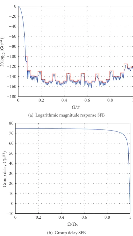
5.2. SFB Prototype Filter. To complete the FBP design we present an example for the narrow-band FIR low-pass SFB prototype filter designed by the procedure in Section 4. This SFB prototype filter is matched to the AFB prototype filter of Section 5.1such that the distortion function of an oversamplingI-channel complex-modulated FIR filter bank according to (11) approximates a constant delay (LP allpass function). At the same time the constant delay is supposed to be the smallest possible one as figured out inSection 2.
The magnitude response specifications of the stopband are chosen according to the considerations made in [7]. They are more strict than those of the AFB for reasons stated in [7]. For the implementation of the design algorithm the built-in functionfminconof the Optimization Toolbox of Matlab is used again. The given stopband magnitude specifications are met for the filter lengthNg=152. The number of frequency points is againL=1024.
Figure 4(a)shows the logarithmic magnitude frequency
response. The tolerance mask for the stopband is depicted
−180 −160 −140 −120 −100 −80 −60 −40 −20 0
20
log
10
|
G
(e
j
Ω)
|
0 0.2 0.4 0.6 0.8 1
Ω/π
(a) Logarithmic magnitude response SFB
−10 0 10 20 30 40 50 60 70 80
Gr
o
u
p
d
el
ay
G
(e
j
Ω)
0 0.2 0.4 0.6 0.8 1
Ω/ΩS
(b) Group delay SFB
Figure4: Narrow-band SFB prototype filter.
in red color. We notice that this time the tolerance mask is always touched by the magnitude response. This can be traced back to the fact that, for the SFB, the steps of the tolerance mask are much smaller, not exceeding 20 dB, except for the region next to the transition band.
The group delay in the passband and transition band is depicted in Figure 4(b). The group delay is again approx-imately constant with the mean value τg,SFB = 74. This time the group delay does not decay below the value of
τg,SFB=70 roughly up to the frequency where the magnitude
response is 80 dB. The obtained SFB prototype filter is again minimum-phase, even though no demand is made in this regard according toSection 4.
Figure 5(a) illustrates the logarithmic magnitude
−0.8 −0.6 −0.4 −0.2 0 0.2 0.4 0.6 0.8
20
log
10
|
Fdist
(e
j
Ω)
|
0 0.2 0.4 0.6 0.8 1
Ω/π
(a) Logarithmic magnitude response of the distortion function.
124 125 126 127 128 129 130 131 132 133
Gr
o
u
p
d
el
ay
Fdist
(e
j
Ω)
0 0.2 0.4 0.6 0.8 1
Ω/π
(b) Group delay of the distortion function.
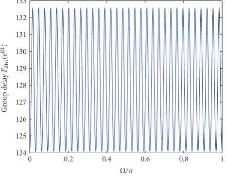
Figure5: Distortion Function.
The group delay of the distortion function is depicted in
Figure 5(b). It varies around the feasible value of 2I = 128
derived inSection 2.3with a deviation of±4 corresponding to±3%.
The downsampled FBP impulse response fdist(mI) in compliance with (15) is depicted inFigure 6(here all zero coefficients have been omitted). The number(Ns−1)/I + 1 of non-zero coefficients is four, since Ns according to (13) results in Ns = 241. Here the dominating coefficient is the second one, thus explaining the overall delay of 128 as shown above. Note that, due to the even number of non-zero coefficients, no exact linear-phase distortion function is possible. The only way to approximate an allpass according to the considerations in Section 2 is by bringing the coefficients as close as possible to a ideal delay.
0 0.1 0.2 0.3 0.4 0.5 0.6 0.7 0.8 0.9 1
0 0.5 1 1.5 2 2.5 3
m
Figure6: Distortion function in time-domainfdist(mI).
6. Conclusion
In this contribution, a new iterative approach for the design of analysis and synthesis prototype filters of oversampling uniform complex-modulated FIR filter bank pairs is pro-posed, such that the overall FBP signal delay is minimized, and the subband signals experience short delay.
We have shown that in the time-domain the distortion function can be expressed as a simple FIR filter impulse response. Based on these results we have shown that the mean value of the group delay is restricted to integer multiples of the number of channels.
For the first design step we have introduced a novel procedure for the design of low-delay AFB FIR prototype filters with approximately linear-phase in the passband and the transition band. This procedure is based on convex con-strained optimization which guarantees unique solutions. To this purpose we have introduced a convex objective function for group delay minimisation, which is based on a particular representation of the group delay according to [20]. The magnitude requirements are used as design constraints.The magnitude specifications (e.g., for hearing aids those derived in [7]) serve as stopband constraints to control aliasing.
Finally, we have discussed the properties of the design algorithm with reference to an example. The example shows that the group delays of the prototype filters obtained using the presented procedures exhibit almost constant group delay not only in the passband but also in the transition band. The mean value of the group delay ranges below that of linear-phase filters of the same length. The observed overall signal delay lies within the tolerances defined in [7] and approximates the feasible delay as described inSection 2.
A comparison between the proposed design method against several other approaches to the design of oversam-pling complex-modulated FBS is not performed here, since [22] treats this topic thoroughly, where approaches by DAM et al. [15], by St¨ocker et al. [23], and by B¨auml and S¨orgel [24] are compared.
Future investigations will be devoted to the application of the prototype filter pair presented in this contribution to uniform, complex-modulated filter banks with additional subband signal manipulation. We will particularly investigate whether or not amplification of subband signals has an impact on the group delay of the distortion function.
References
[1] V. Harnacher, J. Chalupper, J. Eggers, et al., “Signal processing in high-end hearing aids: state of the art, challenges, and future trends,” EURASIP Journal on Applied Signal Processing, vol. 2005, no. 18, pp. 2915–2929, 2005.
[2] M. A. Stone and B. C. J. Moore, “Tolerable hearing aid delays. I. Estimation of limits imposed by the auditory path alone using simulated hearing losses,”Ear & Hearing, vol. 20, no. 3, pp. 182–192, 1999.
[3] M. A. Stone and B. C. J. Moore, “Tolerable hearing aid delays. III. Effects on speech production and perception of across-frequency variation in delay,”Ear & Hearing, vol. 24, no. 2, pp. 175–183, 2003.
[4] P. Vary,Ein Beitrag zur Kurzzeitspektralanalyse mit digitalen Systemen, Ph.D. dissertation, Universit¨at Erlangen-N¨urnberg, Erlangen, Germany, 1978.
[5] P. P. Vaidyanathan, Multirate Systems and Filter Banks, Prentice-Hall, Englewood Cliffs, NJ, USA, 1993.
[6] H. G. G¨ockler and A. Groth,Multiratensysteme, Schlembach Fachverlag, Willburgstetten, Germany, 2004.
[7] D. Alfsmann, H. G. G¨ockler, and T. Kurbiel, “Frequency-Domain Magnitude Constraints for Oversampling Complex-Modulated NPR Filter Bank System Design Ensuring a Prescribed Signal-to-Distortion Ratio,” to be published. [8] A. V. Oppenheim and R. W. Schafer, Discrete-Time Signal
Processing, Prentice-Hall, London, UK, 1989.
[9] T. Kurbiel, D. Alfsmann, and H. G. G¨ockler, “Design of highly selective quasi-equiripple FIR lowpass filters with approxi-mately linear phase and very low group delay,” inProceedings of the European Signal Processing Conference (EUSIPCO ’08), EURASIP, Lausanne, Switzerland, 2008.
[10] T. F. Liau, M. A. Razzak, and L. G. Cuthbert, “Phase constraints on fir digital filters,”Electronics Letters, vol. 17, no. 24, pp. 910–911, 1981.
[11] H. Baher, “Fir digital filters with simultaneous conditions on amplitude and delay,”Electronics Letters, vol. 18, no. 7, pp. 296–297, 1982.
[12] E. Sharestani and L. G. Cuthbert, “Fir digital filters designed to a groupdelay characteristic,”Electronics Letters, vol. 21, no. 12, pp. 542–544, 1985.
[13] X. Zhang and T. Yoshikawa, “Design of FIR Nyquist filters with low group delay,”IEEE Transactions on Signal Processing, vol. 47, no. 5, pp. 1454–1458, 1999.
[14] M. Lang,Algorithms for the constrained design of digital filters with arbitrary magnitude and phase responses, Ph.D. disserta-tion, Vienna University of Technology, Vienna, Austria, June 1999.
[15] H. H. Dam, S. Nordholm, A. Cantoni, and J. M. de Haan, “Iterative method for the design of DFT filter bank,”IEEE Transactions on Circuits and Systems II, vol. 51, no. 11, pp. 581– 586, 2004.
[16] H. H. Dam, S. Nordholm, and A. Cantoni, “Uniform FIR filterbank optimization with group delay specifications,”IEEE Transactions on Signal Processing, vol. 53, no. 11, pp. 4249– 4260, 2005.
[17] W. Kellermann, “Analysis and design of multirate systems for cancellation of acoustic echoes,” inProceedings of IEEE Inter-national Conference on Acoustics, Speech and Signal Processing (ICASSP ’88), pp. 2570–2573, 1988.
[18] K. F. C. Yiu, N. Grbic, S. Nordholm, and K. L. Teo, “Multicri-teria design of oversampled uniform DFT filter banks,”IEEE Signal Processing Letters, vol. 11, no. 6, pp. 541–544, 2004. [19] K. F. C. Yiu, N. Grbic, S. Nordholm, and K. L. Teo, “A hybrid
method for the design of oversampled uniform DFT filter banks,”Signal Processing, vol. 86, no. 7, pp. 1355–1364, 2006. [20] H. W. Sch¨ußler,Digitale Signalverarbeitung 1, Springer,
Hei-delberg, Germany, 5th edition, 2008.
[21] T. W. Parks and C. S. Burrus,Digital Filter Design, John Wiley & Sons, New York, NY, USA, 1987.
[22] D. Alfsmann, H. G. G¨ockler, and T. Kurbiel, “Filter banks for hearing aids applying subband amplification: a comparison of different specification and design approaches,” inProceedings of the 17th European Signal Processing Conference (EUSIPCO ’09), Glasgow, Scotland, August 2009.
[23] C. St¨ocker, T. Kurbiel, D. Alfsmann, and H. G. G¨ockler, “A novel approach to the design of oversampling complex-modulated digital filter banks,” inProceedings of the 17th Euro-pean Signal Processing Conference (EUSIPCO ’09), Glasgow, Scotland, August 2009.