Volume 2010, Article ID 165654,16pages doi:10.1155/2010/165654
Research Article
Cosine Modulated and Offset QAM Filter Bank
Multicarrier Techniques: A Continuous-Time Prospect
Behrouz Farhang-Boroujeny and Chung Him (George) Yuen
ECE Department, University of Utah, UT 84112, USA
Correspondence should be addressed to Behrouz Farhang-Boroujeny,[email protected]
Received 11 May 2009; Revised 23 September 2009; Accepted 14 December 2009
Academic Editor: Pierre Siohan
Copyright © 2010 B. Farhang-Boroujeny and C. H. (George) Yuen. This is an open access article distributed under the Creative Commons Attribution License, which permits unrestricted use, distribution, and reproduction in any medium, provided the original work is properly cited.
Prior to the discovery of the celebrated orthogonal frequency division multiplexing (OFDM), multicarrier techniques that use analog filter banks were introduced in the 1960s. Moreover, advancements in the design of perfect reconstruction filter banks have led to a number developments in the design of prototype digital filters and polyphase structures for efficient implementations of the filter bank multicarrier (FBMC) systems. The main thrust of this paper is to present a tutorial review of the classical works on FBMC systems and show that some of the more recent developments are, in fact, reinventions of multicarrier techniques that have been developed prior of the era of OFDM. We also review the recent novel developments in the design of FBMC systems that are tuned to cope with fast fading wireless channels.
1. Introduction
Orthogonal frequency division multiplexing (OFDM) is the most dominant technology that has been researched and has been deployed for broadband wireless communications. OFDM is attractive because of a number of advantages that it offers. First, orthogonality of subcarrier channels allows trivial equalization; one scalar gain per subcarrier. Second, closely spaced orthogonal subcarriers partition the available bandwidth into a collection of narrow subbands. Adaptive modulation schemes are then applied to sub-bands to maximize bandwidth efficiency/transmission rate. Third, the very special structure of OFDM symbols simplifies the tasks of carrier and symbol synchronizations. These points are well understood and documented in the literature [1,2]. More recent works propose extending the use of OFDM to multiple access applications. Multiple access OFDM, or orthogonal frequency division multiple access (OFDMA), has recently been proposed in a number of standards and proprietary waveforms (e.g., [3]). Some particular forms of OFDMA have also been proposed for cognitive radio systems [4]. In OFDMA, a subset of the subcarriers is allocated to each user node in a network. These users signals must be
synchronized at the receiver input to prevent intercarrier interference. OFDMA works well in the network downlink of a base station, since all of the subcarriers are transmitted from the same base station and, thus, can easily be syn-chronized. However, synchronization is not trivial in the network uplink where a number of nodes are transmitting separately. For OFDMA to work well in this scenario, the signals from various nodes must be synchronized at the base station, that is, they should be received as a set of orthogonal signals. Since, in practice, perfect synchronization may not be possible, additional signal processing steps have to be taken to minimize interference among signals from different nodes. Such steps add significant complexity to an OFDMA receiver; see [5] and the references therein. The problem is worse in a cognitive radio setting where both primary (non-cognitive nodes) and secondary users (cognitive nodes) transmit independently and may be based on different standards. Therefore, the existing OFDMA may not be able to satisfactorily address the needs of efficient use of spectra in the next generation of communication networks.
understood, fact is that the first multicarrier techniques which were developed before the invention of OFDM used filter banks for synthesis and analysis of multicarrier signals. Such filter banks can be designed with small side-lobes, thus, are ideal choice in multiple access and cognitive radio applications [6]. The first proposal came from Chang [7], who presented the conditions required for signaling a parallel set of pulse amplitude modulated (PAM) symbol sequences through a bank of overlapping filters within a minimum bandwidth. To transmit PAM symbols in a bandwidth efficient manner, Chang’s signaling is based on staggering a number of overlapping vestigial side-band (VSB) modulated signal sequences. Saltzberg [8], extended the idea and showed how the Chang’s method could be modified for transmission of quadrature amplitude modulated (QAM) symbols, in a double side-band modulated format. Efficient digital implementation of Saltzberg’s multicarrier system through polyphase structures first introduced by Bellanger et al. [9,10], was studied by Hirosaki [11,12], and was further developed by others [13–21]. Both Chang’s and Saltzberg’s methods belong to a class of multicarrier techniques that may be referred to as filter bank multicarrier (FBMC) systems.
The pioneering work of Chang [7], on the other hand, has received less attention within the signal processing com-munity. Those who have cited [7], have only acknowledged its existence without presenting much details, for example [11,16,19,22]. For instance, Hirosaki who has extensively studied and developed digital structures for implementation of Saltzberg’s method, [11,16], has made a brief reference to Chang’s method and noted that since it uses VSB modulation and thus its implementation require a Hilbert transforma-tion, it is more complex than that of Saltzberg’s method. He thus proceeds with a detail discussion and development of multirate structures for the Saltzberg’s method only. On the other hand, a vast literature in digital signal processing has studied a class of multicarrier systems that has been referred to as discrete wavelet multitone (DWMT). The initial works on DWMT are [23–25]. In the period of 1995 to 2003 a fair number of contributions from various authors appeared in the literature, for example [26–30]. Reference [30], in particular, did a thorough study of DWMT and noted that this method operates based on cosine modulated filter banks which were extensively developed in the 1980’s in the context of compression techniques [31]. The fact that DWMT uses cosine modulated filter banks has also been acknowledged by other authors, for example [28]. Reference [30] also greatly simplified the equalizer structure that was originally proposed in [23–25] and widely adopted by others. Moreover, [30] noted that a DWMT signal is synthesized by aggregating a set of VSB modulated PAM signal sequences. However, most of the works on DWMT (including [30]) have made no direct reference to Chang’s method. In other words, the Chang’s multicarrier method was re-invented, with a strong multirate signal processing flavor, in the 1990’s. Part of our attempt in this paper is to show this very important relationship between what has been done over 40 years ago, and the independent developments on DWMT/cosine modulated multicarrier techniques that have been developed in more recent years. We also hope that the tutorial treatment
of the Chang’s method in this paper will facilitate a more in-depth understanding of the DWMT/cosine modulated multicarrier literature. Another important point to note is that although DWMT was originally developed with DSL applications in mind, it was never adopted in any of DSL standards. However, DWMT has recently found its way to power line communications (PLC) that share a very similar environment to that of DSL [32].
It is also interesting to note that the researchers who studied filter banks developed a class of filter banks which were called modified DFT (MDFT) filter bank [33]. Careful study of MDFT reveals that this, although done indepen-dently, is in effect a reformulation of Saltzberg’s filter bank in discrete-time and with emphasis on compression/coding. The literature on MDFT begins with the pioneering works of Fliege [34], and later has been extended by others, for example [35–38].
As a final note in this introductory section, we wish to bring the attention of reader to various terminologies that have appeared in the literature related to Chang’s and Saltzberg’s MCFB methods and many further extensions that have been made by others. In the pioneering works of Chang [7] and Saltzberg [8] no specific name has been given to the multicarrier modulation types that they introduce, except that Chang notes PAM symbols are transmitted via its signaling method and Saltzberg notes that how QAM symbols can be transmitted with the same bandwidth efficiency. Even the fact that Chang’s subcarrier modulation is VSB has not been explicitly noted in his paper [7]. Apparently, the name staggered QAM was used for the type of modulation suggested in [8], for the first time, in [39]. Later, Hirosaki [12] used the terminology orthogonally multiplexed QAM (OQAM). OQAM was later referred to as OFDM-OQAM by many authors, for example [13–15,17–
21], with the acronym OQAM standing for offset QAM, reflecting the fact that the in-phase and quadrature of each QAM symbol are time offset with respect to each other. A few others have named it pulse-shaped OFDM [40–
47]. These use of different terminologies in parallel with the independent introduction of MDFT, which is based on the same fundamental principles as OQAM, has made the literature on FBMC techniques somewhat blurred [48], and thus confusing to any novice who wishes to begin a research in this area.
The same is true for Chang’s method and the inde-pendent, but related, works that have been published later. Among these [25], that received a significant level of attention (see [30] and the references therein), independently (but, effectively) presented Chang’s modulation scheme under the name discrete wavelet multitone (DWMT). The name DWMT is somewhat confusing here as the proposed method in fact uses cosine modulated filter banks for which the use of the terminology wavelet is a misnomer. Cosine modulated filter banks belong to the class of uniform filter banks, meaning that all subbands have the same width. Wavelets, on the other hand, are referred to filter banks whose subband widths increase exponentially with the respective carrier/center frequencies. The adjectivedyadic
also interesting to note that there exists another class of multicarrier techniques that are based on true wavelets (i.e., wavelets with dyadic bandwidths), for example, see [49]. Moreover, it is worth noting that the IEEE P1901 working group who has adopted a DWMT type modulation for part of PLC standard, has called it wavelet-OFDM. On the other hand, some authors have preferred the name cosine modulated filter bank OFDM (CMFB-OFDM). In [50], where a more thorough study of DWMT/CMFB-OFDM to VDSL has been presented, the shorter name cosine-modulated multitone (CMT) has been proposed, following the terminology filtered multitone (FMT) [51–
53], another FBMC candidate that was proposed (but was never adopted) in VDSL standard. In this paper, we use CMT when reference is made to the Chang’s method (and its extensions). We also introduce and use the terminology staggered-modulated multitone (SMT) for the Saltzberg’s method (and its extensions).
In this paper, we first present a novel tutorial review of Chang’s and Saltzberg’s FBMC methods with the goal of making these classical works more accessible to the signal processing community. These are presented in Sections2and
3, respectively. Similarities and differences of CMT and SMT are discussed inSection 4. InSection 5further development that has been made on extensions on Chang’s and Saltzberg’s methods are discussed. The emphasis in this section is on the design of prototype filters for CMT and SMT. A brief review of equalization of CMT and SMT systems is presented
inSection 6. The concluding remarks are made inSection 7.
Even though, any modern implementation of a CMT or SMT system will be in discrete-time, the derivations in this paper are in terms of continuous-time signals and systems. The choice of the continuous-time formulation here simplifies the derivations and will also provide more insight to the fundamental properties of both CMT and SMT as well as their similarities and differences. We believe our approach also provides a meaningful intuitive understanding of the extension of CMT and SMT that are discussed inSection 5.
2. Cosine Modulated Multitone (CMT)
In CMT, a number of parallel streams of PAM data symbols are transmitted through a set of vestigial side-band (VSB) subcarrier channels. Moreover, the subcarrier channels are minimally spaced to maximize the bandwidth efficiency of the system. To explain what constitutes to the minimally spaced subcarrier channels, we recall that the minimum bandwidth for a transmission rate ofR=1/TQAM symbols per second, where T is symbol spacing in seconds, is B =
1/THz, [54]. This concept is demonstrated in Figure 1, where the magnitude response of a Nyquist filter with an excess bandwidth ofα/2Tis presented. Clearly, the minimum bandwidth is achieved when α = 0. In CMT, where data symbols are PAM, noting that each PAM symbol is equivalent to one half of a QAM symbol, one may argue that the minimum bandwidth for transmission of R = 1/T PAM symbols per second isB = 1/2THz. To further clarify this point and pave the way for development of a CMT system, we continue with an introduction to a VSB channel.
|P(f)|
−1 +2 α
T − 1 2T
1 2T
1 +α 2T
f
Figure1: Magnitude response of a Nyquist filter with an excess bandwidth of α/T. Note that P(f) has the total banwidth (1 + α)/2T−(−(1 +α)/2T)=(1 +α)/T, and the minimum bandwidth 1/Tis achieved whenα=0.
Modulation Demodulation
f
−fc fc f
Figure2: Vestigial side-band modulation and demodulation. The figure depicts the signals spectra.
2.1. Vestigial Side-Band Modulation. Figure 2 presents the process of taking a baseband signal, modulating it to a VSB channel, and demodulating the modulated signal back to the baseband. As shown, for modulation, this process divides the spectrum of the baseband signal in two parts, takes one part to modulate a complex sine-wave at the positive frequency fc (i.e., multiply byej2π fct) and the other part to
modulate a complex sine-wave at the negative frequency−fc
(i.e., multiply by e−j2π fct). Demodulation is performed by
reversing these steps.
Next, we explain the above steps in a form closely related to CMT modulation. Consider the communication system shown inFigure 3(a). The input signals(t) is an impulse train corresponding to a PAM data streams[n] at the rate of 1/T, viz.,
s(t)=
∞
n=−∞
s[n]δ(t−nT). (1)
Modulation Demodulation
h(t)ej(π/2T)t s1(t) ej2π fct
x1(t)
s(t)
h(t)e−j(π/2T)ts2
(t) x2(t) e−j2π fct
x(t)
Channel y (t)
e−j2π fct
y1(t)
h(t)ej(π/2T)t s1(t)
s(t)
ej2π fct
y2(t)
h(t)e−j(π/2T)t
s2(t) (a)
Modulation Demodulation
h(t)ej(π/2T)t {·} ej2π fct
{·}
x1(t) s1(t)
s(t)
x(t) Channel
y(t) e−j2π fct
h(t)ej(π/2T)t s
(t)
s(t) y1(t)
(b)
Figure3: Vestigial side-band modulation and demodulation. (a) Detailed block diagram. (b) Simplified block diagram.
andh(t) is a real function of time. Hence, the same filter is used at the receiver as a matched pair to the transmit filter
h(t). However, we note that in the original work of Chang, [7], this restriction is not imposed on h(t). Nevertheless, in practice, when filters are realized digitally, the use of zero-phase/symmetric filters may be the most useful case. Moreover, most of the derivations that follow become trivial when h(t) is symmetric. We will make some comments on the more general pulse-shaping filters that have been proposed in [7] later; seeSection 2.3.
The filter h(t)ej(π/2T)t in the upper-left branch of
Figure 3(a)is a modulated version ofh(t) that is centered at
f = 1/4T (note that π/2T = 2π×(1/4T)). Similarly, the filter in the lower-left branch ofFigure 3(a)is a modulated version ofh(t) that is centered at f = −1/4T. Accordingly, the signalss1(t) ands2(t) are the upper- and lower-side bands
of a baseband signal. These signals are further modulated to the carrier frequencies fcand−fcto obtain the signalsx1(t)
andx2(t), respectively. The transmit signalx(t) is obtained
by addingx1(t) andx2(t). On the other hand, the received
signal y(t) is demodulated to obtain the upper- and lower-side baseband signals s1(t) and s2(t), respectively. These
are then added to obtain the output s(t) whose samples, when taken at a correct timing phase, are estimates of the transmitted data symbols s[n]. When channel is ideal, that is, y(t) = x(t), these estimates are accurate. The presence of channel noise, clearly, results in some unrecoverable error in the estimates. However, if the channel is flat fading, that is, is characterized by a flat gain, a single-tap equalizer with a complex-valued tap-weight equal to the inverse of the channel gain can be used to combat the channel distortion. Some general comments on the equalizers in FBMC systems will be presented later inSection 6.
Next, we note thats(t),h(t),x(t),y(t), ands(t) are real-valued signals. We take advantage of this fact to simplify the transceiver structure ofFigure 3(a). The fact thats(t) is real-valued implies thatx1(t) and x2(t) are complex conjugates
of each other and, thus,x(t) = 2R{x1(t)}. This means, in
Figure 3(a), the branch that leads tox2(t) may be removed.
This results in the left-half side of the simplified block diagram presented inFigure 3(b). Similarly, the fact thaty(t) is real-valued can be used to simplify the demodulation part ofFigure 3(a)as inFigure 3(b).
Next, we take a closer look at h(t) and discuss how it should be selected in order to result in an intersymbol inter-ference (ISI) free equivalent baseband channel. Assuming an ideal channel between the transmit and receive antennas, the equivalent baseband channel, [54], froms(t) tos(t) has the impulse response
g(t)=Rh(t)ej(π/2T)th(t)ej(π/2T)t
=Rej(π/2T)t ∞
−∞h(τ)h(t−τ)dτ
,
(2)
wheredenotes convolution. Letting∞−∞h(τ)h(t−τ)dτ= p(t), (2) simplifies to
g(t)=p(t) cos
π
2Tt
. (3)
We recall that for ISI free transmission, g(t) has to be a Nyquist pulse with zero crossings at the points t = nT, for all nonzero integer values of n. Hence, here, ISI free transmission through the VSB channel is achieved, if
implies that forg(t) to be a Nyquist pulse, it is sufficient that
p(nT) be equal to zero at non-zero even values of n. This means p(t) has to be a Nyquist pulse with zero-crossings at the interval 2T. In other words, p(t) has to be a Nyquist pulse that we would use if the data rate was 0.5/T, that is, one half of the rate ofs[n]. This, in turn, implies thath(t) should be asymmetricsquare-root Nyquist filter designed for a data rate of 0.5/T. This result is in line with the fact that the bandwidth of VSB is one half of that of a double-side band (DSB) channel.
2.2. Aggregating VSB Subcarrier Channels. A CMT signal is obtained by adding a number of VSB modulated signals. As noted earlier, to maximize the bandwidth efficiency of the system, the VSB subcarrier channels across frequency should be spaced at 0.5/T. Also, to control and avoid intercarrier interference (ICI) between different subcarrier channels, it is assumed that the underlying filter bank is designed such that only adjacent channels overlap. Then, the ICI among adjacent channels, as shown below, is resolved by introducing a π/2 phase shift among each pair of adjacent subcarrier channels.
Figure 4 presents the block diagram of a CMT
transceiver. The data signals s0(t) through sN−1(t) are
data symbol signals that are defined as in (1). The receiver outputs, sk[n], are the detected PAM symbols.
By inspection of Figure 4, one finds that each subcarrier channel, say, from the input sk(t) to the output sk[n], is
similar to the single channel case shown in Figure 3(b). Thus, ISI free communication is established by choosing
h(t) to be a square-root Nyquist filter that is designed for a data rate 0.5/T. Also, note that the multiplications by 1, ej((π/T)t+π/2),. . .,ej(N−1)((π/T)t+π/2) are effectively
modulators that organize the subcarrier channels at the center frequencies 0,π/T,. . .,π(N−1)/T. This means the spacing between the adjacent subcarriers isπ/T radian per second or, equivalently 0.5/THz.
To study the ICI between a pair of adjacent channels, consider the impulse response betweensk+1(t) and the point
prior to the sampler at thekth output of the receiver. This is obtained by direct inspection ofFigure 4, and following the same derivations that led to (3), as
g1(t)=R
h(t)ej((3π/2T)t+π/2)h(t)ej(π/2T)t
=Rej((π/2T)t+(π/2)) ∞
−∞h(τ)e
j(π/T)τh(t−τ)dτ
= −sin
π
2Tt ∞
−∞h(τ)h(t−τ) cos
π Tτ
dτ
−cos
π
2Tt ∞
−∞h(τ)h(t−τ) sin
π Tτ
dτ.
(4)
We are interested in the sample values ofg1(t) at the time
instantsnT, for all integer values ofn.
For an even value of n = 2k, one finds that sin((π/2T)2kT)=sin(kπ)=0 and, thus, (4) reduces to
g1(2kT)=(−1)k+1
∞
−∞h(τ)h(2kT−τ) sin
π Tτ
d, (5)
where we have noted that cos(kπ) = (−1)k. Applying a change of variableτtokT+τin (5), we get
g1(2kT)= −
∞
−∞h(kT+τ)h(kT−τ) sin
π Tτ
d=0, (6)
where the second identity follows since the expression under the integral is an odd function of τ. Following a similar procedure, one also finds thatg1(nT)=0 for odd values of
n. These results show that there is no ICI between a pair of adjacent subcarrier channelskandk+ 1.
2.3. More Relaxed Forms of h(t). To keep the derivations simple, so far, we have assumed thath(t) is a symmetric (i.e., zero-phase) square-root Nyquist filter. The pioneering work of Chang, [7], derives the necessary and sufficient constraints that should be imposed onh(t), assuming that at the receiver the matched pair of h(t), that is, h(−t), is used for the signal analysis. The Chang’s constraints, if given in terms of the Fourier transform ofh(t),H(f), and assuming an ideal channel, are the followings:
(1) For practical reasons, it is assumed that h(t) is a real function of time. Accordingly,|H(f)|is an even function of f and∠(H(f)) is an odd function of f. (2) To guarantee ISI free transmission over each
subcar-rier channel,p(t)=h(t)h(−t) must be a Nyquist pulse with regular zero crossings at the intervals of 2T. In the frequency domain, this is equivalent to
∞
k=−∞ P
f − k
2T
=1 (7)
and we may notice that P(f) = H(f)H∗(f) = |H(f)|2. Note that the symmetry assumptionh(t)=
h(−t), made previously, implies thatH(f) is a real function of f, that is, it has zero phase across the frequency. However, sinceP(f) =H(f)H∗(f), the constraint (7) does not require H(f) to be a zero phase filter. In fact, if the only concern is ISI free transmission,H(f) may have any arbitrary phase. In other words, the symmetry assumptionh(t)=h(−t) is not necessary, even though some designs in the past have made this assumption for convenience, for example [55].
(3) To guarantee ICI free transmission across each pair of adjacent subcarrier channels,∠(H(f)), in addition to odd symmetry with respect to the point f = 0 (mentioned above), should also be odd symmetric with respect to the points f = ±1/4T. Moreover, an additional phase shift ofπ/2 must be introduced between each pair of adjacent subcarrier channels. (4) The derivations in [7], and also what have been
presented so far in this paper, are based on the assumption thath(t) is band-limited such that only adjacent subcarrier channels overlap. As is discussed
in Section 5, below, more recent developments on
s0(t)
h(t)ej(π/2T)t
s1(t)
sN−1(t)
h(t)ej(π/2T)t
h(t)ej(π/2T)t
ej((π/T)t+π/2)
. . .
ej(N−1)((π/T)t+π/2)
ej2π fct
Modulation to RF band
{·}
x(t) To channel
(a)
h(t)ej(π/2T)t y(t)
h(t)ej(π/2T)t h(t)ej(π/2T)t
e−j2π fct
. . . e−j(N−1)((π/T)t+π/2)
e−j((π/T)t+π/2)
Demdulation from RF band
{·} {·} {·}
sN−1[n]
s1[n] s0[n] From channel
(b)
Figure4: Block diagram of a CMT transceiver: (a) transmitter; (b) receiver.
The constraints mentioned in items (1) and (2) are standard results from the single carrier communication systems. Thus, we proceed with an attempt to clarify the reasoning behind the constraints mentioned in item (3).
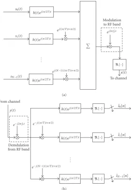
Figure 5(a) presents a pair of typical magnitude and phase
responses of H(f) with the additional phase symmetry condition mentioned in the constraints (3). Figure 5(b)
presents the amplitude and phase responses of H(f) after a right shift of f = 3/4T. This is the channel response corresponding to an adjacent subcarrier to the baseband channel, after demodulation at the receiver. Figure 5(c)
presents the amplitude and phase responses of the VSB matched baseband filter at the receiver. Finally,Figure 5(d)
shows the total channel response from an adjacent subcarrier to a demodulated subcarrier channel at the baseband. This has the transfer function G1(f) = jH∗(f −1/4T)H(f −
3/4T), where the factor j arises from the phase shift of
π/2 among the adjacent subcarrier channels. As seen, as a consequence of the phase symmetry of H(f) around f =
1/4T,G1(f) has a phase response ofπ/2. Moreover, the even
symmetry of|H(f)|leads to an even symmetric magnitude
response|G1(f)|around the point f =1/2T. Finally, taking
the inverse Fourier transform ofG1(f), at the time instant
t =nT, one finds thatg1(nT) is an imaginary number, for
any integer value ofn. Moreover, since in VSB demodulation after matched filtering the imaginary part of the result is ignored, this result shows that the combination of the phase symmetry of H(f) around f = 1/4T and the introduced phase shift ofπ/2 between adjacent subcarrier channels lead to ICI cancellation.
3. Staggered Modulated Multitone (SMT)
Figure 6presents the block diagram of an SMT transceiver.
The data signalss0(t) throughsN−1(t) are continuous-time
signals associated with transmit symbol sequences that are defined as
sk(t)=
∞
n=−∞
sk[n]δ(t−nT), fork=0, 1,. . .,N−1,
H(f) Amplitude
Phase
f 1/4T 1/2T
(a)
H(f−3/4T)
Amplitude Phase
f 1/4T 1/2T 3/4T
(b) H∗(f−1/4T)
Amplitude
Phase f
1/4T 1/2T (c)
jH∗(f−1/4T)H(f−3/4T) Amplitude
Phase=π
2
f 1/2T
(d)
Figure5: Demonstration of ICI cancellation in CMT whenH(f) has a relaxed phase response.
where sk[n] are complex-valued (e.g., QAM or PSK) data
symbols that may be written as
sk[n]=sIk[n] +js Q
k[n], (9)
where the superscripts “I” and “Q” refer to the in-phase and quadrature parts, respectively. Note that at each subcarrier channel, the real and imaginary parts ofsk[n] are separated
and time staggered byT/2. This is done through the pulse shaping filterh(t) which is time shifted to the right on the quadrature branches. Also, note that the same filterh(t) is used at both the transmitter and receiver sides. This, clearly, implies the symmetry conditionh(−t)=h(t) to guarantee a matched filter pair at the two sides. Moreover, we note that the multiplications by 1,ej((2π/T)t+π/2),. . .,ej(N−1)((2π/T)t+π/2)
are effectively modulators that organize the subcarrier chan-nels at the center frequencies 0, 2π/T,. . ., 2π(N−1)/T. This means the spacing between the adjacent subcarriers is 1/T
which is twice of that of the CMT.
The detected data symbols at the receiver output are denoted assk[n]. The filterh(t) should be designed such that
when channel is perfect (i.e., there is no multipath and/or no noise),sk[n] = sk[n]. Next, we proceed and derive the
condition that should be imposed onh(t) for such a perfect recovery.
When only adjacent bands overlap and, thus, one can ignore possible interference from non-adjacent bands, interference may only happen in the following three different ways.
(1) Possible ISI across each phase or quadrature subcar-rier channel, that is, the successive symbol values of
sI
k[n] may interfere with one another, and similarly
forsQk[n].
(2) Cross interference among the sequences sI
k[n] and
sQk[n].
(3) ICI among the adjacent subcarrier signals.
To explore the interferences mentioned in items (1) and (2), we extract the relevant branches from Figure 6 that
connectssI
k(t) ands Q
k(t) toskI[n] ands Q
k[n]. In the absence
of channel, these are presented inFigure 7(a). In presenting this figure, we have noted that the subcarrier modulator
ejk((2π/T)t+π/2)and the demodulatore−jk((2π/T)t+π/2), and also
the modulator to RF,ej2π fct, and the demodulator from RF,
e−j2π fct, cancel each other. If we further note that the output
ofh(t) on the top-left ofFigure 7(a)is a real function of time, and the output ofh(t−T/2) on the bottom-left ofFigure 7(a)
is an imaginary function of time, one can separate the blocks
inFigure 7(a)in two separate channels as inFigure 7(b).
From Figure 7(b), we observe that there is no cross
interference between the in-phase and quadrature of each subcarrier channel in SMT. To avoid ISI in the upper branch
of Figure 7(b), it is necessary and sufficient that h(t) be
chosen such that the combined response h(t) h(t) be a Nyquist pulse. This requirement also guarantees ISI free transmission in the lower (i.e., the quadrature) channel in
Figure 7(b), sinceh(t−T/2)h(t+T/2)=h(t)h(t) and this, in turn, implies that the lower channel also has a Nyquist response.
Figure 8 presents the relevant branches of the k+ 1th
subcarrier channel that may leak signal to the output of the
kth subcarrier channel of an SMT system. Note that, here, the outputssI
k[n] ands Q
k[n] are replaced bysIk[n] ands Q k[n]
to signify that they are interference terms. To explore the interference terms sI
k[n] and s Q
k[n], we study the impulse
responses between each of the inputs and each of the outputs inFigure 8; a total of four impulse responses.
Let us begin with looking at the impulse response between the inputsI
k+1(t) and the output before the sampler
in the upper-right branch of Figure 8. We obtain this by direct inspection ofFigure 8as
g1(t)=R
h(t)ej((2π/Tt)+π/2)h(t)
= − ∞
−∞h(τ) sin
2π T τ
h(t−τ)dτ.
sI 0(t)
jsQ0(t)
sI 1(t)
jsQ1(t)
. . . sI
N−1(t)
jsQN−1(t)
h(t)
ht−T
2
h(t)
ht−T
2
h(t)
ht−T
2)
ej((2π/T)t+π/2)
ej2π fct
ej(N−1)((2π/T)t+π/2)
Modulation to RF band
{·}
x(t) To channel
(a)
sI
0[n]
sQ0[n]
sI
1[n]
sQ1[n]
sIN−1[n]
sQN−1[n] h(t)
{·}
T
{·} {·}
{·}
{·}
. . .
{·}
h(t+T2)
h(t)
h(t+T2)
h(t)
h(t+T2) e−j((2π/T)t+π/2)
e−j2π fct
e−j(N−1)((2π/T)t+π/2) Demodulation
from RF band y(t) From channel
(b)
Figure6: Block diagram of an SMT transceiver: (a) transmitter; (b) receiver.
Substitutingt=nTinto (10), we obtain
g1(nT)= −
∞
−∞h(τ) sin
2π T τ
h(nT−τ)dτ. (11)
Applying the change of variableτtonT/2 +τto this result, we get
g1(nT)=(−1)n+1
∞
−∞h
nT
2 +τ
h
nT
2 −τ
sin
2π T τ
dτ
=0.
(12)
This, clearly, implies that there is no interference from the symbol sequencesI
k+1[n] tosIk[n]. Following the same line of
4. Similarities and Differences of CMT and SMT
From the derivations in Sections 2 and 3, one may find that the key point which results in ICI cancellation among adjacent subcarrier channels in both CMT and SMT is the fact that the same prototype filter h(t) is used at both the transmitter and receiver sides; see (6) and (12) for similarities of the final results. It is interesting to note that ICI cancellation among adjacent subcarrier channels does not impose any other restriction on the choice of h(t). The condition that p(t) = h(t)h(t) be a Nyquist pulse, thus,h(t) should be an even symmetric square-root Nyquist filter, is imposed to avoid ISI. Moreover, h(t) was chosen to be band-limited to minimize ICI among non-adjacent subcarrier channels; a condition that will be relaxed in the next section. Also, as discussed in Section 2.3, for CMT, the even symmetry constraint ofh(t) can be relaxed, if the phase response ofH(f) satisfy an additional odd symmetry condition with respect to the midpoint of its transition band. It is straightforward to follow the same line of argument and show that the same is true in the case of SMT. Therefore, the fundamental concepts based on which both CMT and SMT have been developed are the same.
The main difference between CMT and SMT is the modulation type. In SMT, data symbols are QAM and, thus, the modulation is double side-band (DSB). In CMT, on the other hand, data symbols are PAM and, thus, in order to keep the same bandwidth efficiency, VSB modulation is used. Moreover, if we assume that each DSB subcarrier channel in SMT has the same width as a VSB subcarrier channel in CMT, one finds that symbol rate in each subcarrier channel of CMT will be double that of SMT. Next, we proceed to put these observations in a mathematical formulation.
FromFigure 6, one finds the SMT signal before
modula-tion to RF band is given by
vSMT(t)= N−1
l=0
∞
n=−∞
sI
l[n]h(t−nT)+js Q l [n]h
t−T
2−nT
×ejl((2π/T)t+π/2).
(13)
On the other hand, fromFigure 4, whenTis replaced byT/2 (to equalize the subcarrier bandwidth of CMT with SMT), the CMT signal before modulation to RF band is obtained as
vCMT(t)
=
N−1
l=0
∞
n=−∞ sl[n]h
t−nT
2
ej(π/T)(t−nT/2)ejl((2π/T)t+π/2)
=
N−1
l=0
∞
n=−∞
−jnsl[n]h
t−nT
2
ej(π/T)tejl((2π/T)t+π/2).
(14)
It is instructive to note that bothvSMT(t) and vCMT(t) are
complex-valued baseband signals.
Separating the even and odd terms in (14), we obtain
vCMT(t)= N−1
l=0
∞
k=−∞
−j2ksl[2k]h
t−(2k)T
2
×ej(π/T)tejl((2π/T)t+π/2)
+
N−1
l=0
∞
k=−∞
−j2k+1sl[2k+ 1]h
t−(2k+ 1)T
2
×ej(π/T)tejl((2π/T)t+π/2)
=
N−1
l=0
∞
k=−∞
(−1)ksl[2k]h(t−kT)ej(π/T)tejl((2π/T)t+π/2)
+
N−1
l=0
∞
k=−∞
j(−1)k+1sl[2k+ 1]h
t−T
2 −kT
×ej(π/T)tejl((2π/T)t+π/2)
=
N−1
l=0
∞
k=−∞
(−1)ksl[2k]h(t−kT)
+ j(−1)k+1sl[2k+1]h
t−T
2−kT
×ej(π/T)tejl((2π/T)t+π/2).
(15)
Now, if we remap the bits such thatsIl[n]=(−1) k
sl[2k] and
sQl [n]=(−1) k+1
sl[2k+ 1], we find that
vCMT(t)=vSMT(t)ej(π/T)t. (16)
Applying Fourier transform to both sides of (16), we obtain
VCMT
f=VSMT
f − 1
4T
. (17)
These results show that there is a simple relationship between CMT and SMT. The complex-valued baseband signal vCMT(t) can be constructed by first synthesizing
the correspondingvSMT(t) signal and then modulating the
results with the complex-valued sine-waveej(π/T)t.
Alterna-tively, one may start with synthesizing a respectivevCMT(t)
signal and modulate the result with e−j(π/T)t to obtain a
desired vSMT(t) baseband signal. These also apply to the
respective analysis filter banks. This observation has the following implications.
(i) SMT and CMT are equally sensitive to channel impairments, including time and frequency spread, carrier frequency offset and timing offset. Therefore any analysis done for one is applicable to the other.
ht−T
2 h(t)
ht+T2 h(t)
{·} {·}
sI
k(t)
sQk(t)
sI
k[n]
sQk[n] T (a)
ht−T
2 h(t)
ht+T2 h(t) sI
k(t)
sQk(t)
sI
k[n]
sQk[n] T
(b)
Figure7: Thekth subcarrier channel in an SMT system.
ht−T
2 h(t)
ht+T2 h(t) ej((2π/T)t+π/2)
{·} {·}
sI
k+1(t)
sQk+1(t)
sI
k[n]
sQk[n] T
Figure8: Thekth subcarrier channel in an SMT system.
A detailed study that evaluates sensitivity of CMT and SMT to channel impairments, through independent theoretical derivations for both methods, is presented in [56]. The results of this analysis formally confirm the accuracy of the first statement.
5. Doubly Spread Channels and Prototype Filter
Design
The FBMC approaches proposed by Chang [7] and Saltzberg [8], and the polyphase implementation and equalization structures developed by Hirosaki [12] emphasize on channels with spreading in the time domain only. Possible channel variation in time that leads to spreading in the frequency domain was ignored. Later developments, starting with the pioneering work of Le Floch et al. [42], noted that in some wireless channels both time and frequency spread may be equally important and thus proposed modifications to the SMT prototype filters to limit them equally in time and frequency domains. These may be referred to as designs for
doubly dispersive/spreadchannels.
Part of this section is devoted to a tutorial presentation of prototype filters that are designed for doubly spread channels. However, we note that although such filters are near optimal in time-frequency localization, that is, they attempt to equally limit the filter length in both the time and frequency domain, they are not necessarily the best designs for an arbitrary time-varying channel scenario. For instance,
if a channel variation is very slow, but its time spread is significant, a design that emphasizes on confining the filter response within a minimum bandwidth by using a filter whose impulse response may spread over a long period of time can be a much better choice (of course, ignoring other factors such as complexity and transmission delay). Also, assuming that the channel statistics are known, the optimal design presented in [43] is not the one that equalizes the time and frequency spread of the prototype filter. Nevertheless, the solutions that equally weigh time and frequency spread are widely accepted as they provide good compromised designs.
5.1. Time-Frequency Localized Prototype Filters. Given a time-symmetric signals(t) and its Fourier transformS(f), we define the time and frequency standard deviations
σt=
∞
−∞t
2|s(t)|2dt,
σf =
∞
−∞f
2S(f)2df .
(18)
The Heisenberg-Gabor uncertainty principle states that [57]
σtσf ≥ 1
4π. (19)
In (19), the equality holds whens(t) is the Gaussian pulse
Also, the Gaussian pulse s(t) has the interesting property that S(f) = s(f), that is, it is the same function in both time and frequency domains. Thus, any deviation from the Gaussian pulse, say, to reduce σt, that is, spreading of the
signal in the time domain, will result in an increase of
σf, that is, spreading in the frequency domain. Therefore,
the Gaussian pulse (20) is optimal in the sense that it minimizes the time-frequency productσtσf and also satisfies
the desirable property of equal spreading in both time and frequency domain. However, unfortunately, the Gaussian pulse does not satisfy the Nyquist and other properties of
h(t) which were stated in Sections 2and3for ISI and ICI cancellation in CMT and SMT systems. Noting this, Le Floch et al. [42] and Haas and Belfiore [44] have proposed two different methods for designing pulse shapes that satisfy the conditions necessary for ISI and ICI cancellation in CMT and SMT and result in a time-frequency product that is only slightly greater than the lower limit given by (19).
Both design methods in [42,44] are developed using the time-frequency ambiguityfunction
Aτ,f= ∞
−∞h(t)h(t+τ)e
−j2π f tdt. (21)
The ambiguity functionA(τ,f) has the following interpreta-tion. For f =0,
A(τ, 0)= ∞
−∞h(t)h(t+τ)dt=h(τ)h(−τ) (22)
and the constraintsA(nT, 0)=0, forn /=0, imply thath(t) is a square-root Nyquist filter, hence, a sequence of data symbols that are T spaced can be received free of ISI. On the other hand, the constraints A(0,kΔf) = 0, for any
k, imply that a pair of modulated filters that are spaced across frequency bykΔf do not introduce ICI on each other. Accordingly, if an FBMC system is constructed based on a prototype filterh(t) whose ambiguity function satisfies the constraints
AnT,kΔf=0, forn /=0, and anyk, (23)
where T is the symbol spacing andΔf is carrier spacing, in the absence of channel distortion, ISI and ICI free transmission is achieved.
It has been noted that to achieve a reasonable time-frequency localization which results in a value ofσtσfclose to
the lower limit of 1/4π,TΔf should be given a value greater than 1 [42,44]. On the other hand,TΔf = 2 turns out to be a good choice as it results in prototype filters with a value ofσtσf close to the lower limit 1/4π and also, as discussed
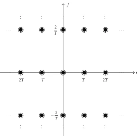
below, is the choice that leads to CMT and SMT systems. When an FBMC system with a prototype filter that satisfies the constraints (23) as well as the equalityTΔf =2 is implemented, complex-valued (i.e., QAM or PSK) data symbols that are spread over a grid of points in the time-frequency phase space at locations nT and 2k/T can be transmitted free of ISI and ICI (assuming an ideal channel) [42,44]. This grid of points are shown inFigure 9, marked as . One may also note that this grid of points have a density of 1/(TΔf)=0.5.
2 T
f
t
−2T −T T 2T
−2
T
Figure 9: Time-frequency phase space for transmission in an FBMC system with QAM symbols.
The trick in SMT and CMT is that replacing complex-valued symbols by real-complex-valued (PAM) symbols, it is possible to double the density of the grid points both along the time and frequency axes. This increases the density of the grid points by a factor of 4. However, since each real symbol is equivalent to half of a complex symbol, this leads to an effective density of one complex symbol per unit area. The principle behind ISI and ICI cancellation after adding the intermediate points lies in the introduction of π/2 phase rotations and the fact that only real or imaginary parts of the analyzed signals are preserved at the receiver outputs. The mathematical derivations that were presented in Sections2
and 3, for the case where only adjacent channels overlap, can be easily extended to any CMT or SMT system whose prototype filter satisfies the constraints (23).
Figure 10presents a grid of points in a phase space for
the case of SMT. The points where an even and odd factors of
π/2 phase are applied to the respective symbols are indicated as and , respectively. A grid of points that corresponds to a CMT system is presented in Figure 11. As one would expect, we note that the density of the grid points in both Figures10and11are the same. This implies that, as discussed before, SMT and CMT have the same spectral efficiency. Moreover, one may note that the time-frequency phase space shown in Figure 11 is obtained from the one inFigure 10
after stretching the time axis by a factor of 2, compressing the frequency axis by a factor of 0.5, and moving the grid points upward by one half of symbol spacing. This, clearly, is another interpretation of the relationship between CMT and SMT that was developed inSection 4.
2 T
1 T f
t
−2T T
2
−T
2
−3T
2 −T T
3T 2 2T
−1
T
−2
T
Figure10: Time-frequency phase space for transmission in SMT.
5.2. Prototype Filter Design for Time-Invariant Channels.
When the channel is a frequency-selective time-invariant one, a fair criterion for designing the prototype filter is minimization of its bandwidth. This results in minimum variation of the channel gain across each subcarrier band, and thus an approximation of flat fading for each subcarrier channel becomes more acceptable. Hence, the use of a single complex-tap equalizer per subcarrier becomes more accept-able. If no constraint is applied to the desired prototype filter, the optimum design will be an ideal filter with the transfer function
Hf=
⎧ ⎪ ⎪ ⎨ ⎪ ⎪ ⎩
1, f≤ 1
2T,
0, otherwise.
(24)
This is a square-root Nyquist filter with roll-offfactorα=0, thus, results in an infinite length and, hence, an unrealizable, filter. To get a realizable filter, a roll-off factor α > 0 is introduced. In particular, any square-root raised-cosine filter with a roll-offfactor 0 < α ≤ 1 will result in a realizable SMT system with perfect ISI and ICI cancellation. In the pioneering work [8] and also in [42], the choice of
Hf=
⎧ ⎪ ⎪ ⎨ ⎪ ⎪ ⎩
cos
π f T
2
, f≤ 1 T
0, otherwise,
(25)
which is a square-root raised-cosine filter with roll-offfactor
α = 1 was suggested. This selection of H(f) provides a good compromise solution. Because of its relatively relaxed transition bands, it can be well approximated with a relatively short filter, and still can achieve a very high attenuation in the stopband. Design methods that find optimum filters with finite length and good attenuation in the stopband have been reported in the literature [55,58].
1 4T
3 4T 5 4T
7 4T f
t
−2T
−1
4T
−T T 2T
−43
T
−45
T
−7
4T
Figure11: Time-frequency phase space for transmission in CMT.
5.3. Isotropic Orthogonal Transform Algorithm (IOTA) Pro-totype Filter Design. IOTA design/algorithm was first intro-duced by Alard [59] and was put in archival journals by Le Floch et al. [42]; see also [60] for further developments. The algorithm starts with the Gaussian pulsegα(t)= 4
√
2αe−παt2
and convert it to the orthogonalized pulse
hα(t)=Oτ0F
−1O
ν0Fgα(t), (26)
where the parameters τ0 and ν0 are defined below, F
andF−1, respectively, denote Fourier and inverse Fourier
transforms, andOais an orthogonalization operator defined
as
y(u)= x(u)
a∞k=−∞|x(u−ka)|2
. (27)
This procedure results in a pulse shape hα(t) which after
applying time scaling to it can be converted to a filter that satisfies the ambiguity function constraints given in (23); see [42,60] for more details.
5.4. Hermite Functions Based Prototype Filter Design. Haas and Belfiore [44] noted that the set of functions
Dn(t)=hn √
2πt, forn=0, 4, 8,. . ., (28)
where hn(t) = e−t 2/2
(dn/dtn)e−t2
, satisfy the identity
FDn(t) = Dn(f). They have thus concluded that a pulse
shape h(t) formed by linearly combining Dn(t), for n =
0, 4, 8,. . .also satisfies the identityFh(t)=h(f). They have then presented a procedure for combiningDn(t) functions
to construct a pulse shapeh(t) whose ambiguity function satisfies the constraints (23).
−140
−120
−100
−80
A
m
plitude
(dB)
−60
−40
−20 0
−3 −2 −1 0 1 t/T
2 3
Nyquist Hermite IOTA
Figure 12: Magnitude of impulse response of three designs of prototype filter of length 6T.
frequency domain responses of a Nyquist design (with roll-offfactor of 1) [58], a Hermite design [44], and an IOTA design [42, 60] are presented. All filters are designed for a finite duration time response 6T. As one would expect, the Nyquist design provides the narrowest response in the frequency domain, at a cost of a wider response in the time domain. IOTA and Hermite designs, for most parts, are quite similar. Hermite design outperforms IOTA design over the intervals of time and frequency that the magnitude of the responses are below−40 dB. We may also note that while the pass and transition bands of the Nyquist design is over the interval−1/T to 1/T, this is much wider in the cases of Hermite and IOTA designs.
6. Channel Impact and Equalization
The derivations and discussions so far were based on the assumption that the channel was ideal, that is, a channel with a constant gain and a constant group delay across the frequency band that includes all the subcarrier channels. However, we note that the main reason for using any multicarrier technique, including CMT and SMT, is to deal with frequency selective channels, that is, the channels whose gain vary across the frequency band and thus may suffer from a significant level of ISI and ICI. On the other hand, the most important advantage of multicarrier techniques is that they greatly simplify the task of channel equalization – a mechanism that is used to combat ISI and ICI. In a single carrier system, when the channel suffers from a significant level of ISI, a transveral/FIR filter with many taps have to be used to generate a response that resembles the inverse of the channel gain across the transmission band. Such inversion will result in noise enhancement across the portion of the frequency band that the channel gain is low [61]. Adaptation of the equalizer tap weights also may not be a straightforward task. Wireless multipath channels are always time-varying
−140
−120
−100
−80
A
m
plitude
(dB) −60
−40
−20 0
−8 −6 −4 −2 0 2 f T
4 6 8
Nyquist Hermite IOTA
Figure13: Magnitude of frequency response of three designs of prototype filter of length 6T.
and thus the equalizer should be adapted to track channel variations. The speed of tracking decreases as the length of equalizer increases [62,63]. Hence, when the channel is highly frequency selective and as a result a long equalizer has to be used, an equalizer adaptation algorithm may not be able to cope with the channel variation.
The above problems are solved or, at least, greatly moderated when a multicarrier method is adopted. In the case of OFDM, as long as the duration of the channel impulse response is shorter than the cyclic prefix length and channel variation over each OFDM symbol is negligible, a frequency selective channel converts to a number of subcarrier channels with flat gains. In CMT and SMT, the assumption of a flat gain over each subcarrier channel is true only approximately. However, the accuracy of this approximation improves as the bandwidth of each subcarrier channel decreases. Here, the bandwidth is defined as a frequency range that include the pass and transition bands of each subcarrier channel. Like OFDM, in FBMC systems also equalization is performed separately on each subcarrier channel. In [24] and many subsequent papers on DWMT, for example [26–
29], subcarrier equalization was performed by combining signals from a center and two adjacent subcarrier bands. This which results in an equalizer with many taps per subcarrier, was later proved to be unnecessary and a much simpler equalizer that effectively needs two real taps per subcarrier is sufficient [30]. The pioneering work of Hirosaki [12], that explored polyphase structures for SMT, has introduced an equalization technique similar to [30]. However, this early work apparently remained unnoticed to the researchers on DWMT/CMT, probably because they saw DWMT/CMT as a method significantly different from SMT.
bands, the equalizer at each subcarrier channel should be a fractionally spaced one. The sampling at each subcarrier channel should be equal to the total bandwidth of the respective subcarrier signal. This in the case of the Nyquist prototype filter that was presented in the previous section results in aT/2-spaced equalizer. In the cases of IOTA and Hermite filters equalizers with more closely spaced taps are required since these filters have wider bandwidths than their Nyquist counterpart.
It is also worth noting that equalization is one of the least explored issues in FBMC systems and thus further research in this is necessary. In doubly spread channels, in particular, the use of IOTA and/or Hermite prototype filters is intuitively sound. However, this is without consideration of the practical fact that adaptive equalizers with non-trivial tracking algorithms may change the balance between a good prototype filter and an increase in the number of equalizer taps for a given performance—good filters like IOTA and Hermite may need the use of fractionally spaced equalizer with more taps than a Nyquist based system and thus may suffer more from slow convergence and/or tracking problems.
7. Conclusion
A tutorial overview of two filter bank multicarrier (FBMC) techniques that were proposed in the early days of develop-ment of digital communication systems was presented. The first method constructs a multicarrier signal by aggregating a number of vestigial side band (VSB) signals that carry a set of pulse amplitude modulated (PAM) symbol sequences. The second method, on the other hand, transmits a set of staggered quadrature amplitude modulated (QAM) symbol sequences. Both methods achieve maximum bandwidth efficiency by using subbcarrier signals that are minimally spaced and designed such that could be perfectly separated at the receiver side. It was also shown that these two methods are closely related through a modulation step and a one-to-one mapping of data symbols. Additional advancements in further development of FBMC systems, particularly, the various approaches that have been proposed for designing the underlying prototype filters were also reviewed and compared against each other.
Acknowledgments
The authors are grateful to anonymous reviewers whose constructive comments led to a significant improvement of this paper. They are also grateful to Pierre Siohan for providing them the MATLAB code for generating the IOTA filters. This work was supported by the National Science Foundation Award 0801641.
References
[1] R. Van Nee and R. Prasad,OFDM for Wireless Multimedia Communications, Arthec House, Boston, Mass, USA, 2000. [2] Y. Li and G. L. St¨uber, Eds.,Orthogonal Frequency Division
Multiplexing for Wireless Communications, Springer, New York, NY, USA, 2006.
[3] “Air interface for fixed and mobile broadband wireless access systems,” IEEE Std. 802.16e, 2005.
[4] T. A. Weiss and F. K. Jondral, “Spectrum pooling: an innova-tive strategy for the enhancement of spectrum efficiency,”IEEE Communications Magazine, vol. 42, no. 3, pp. S8–S14, 2004. [5] M. Morelli, C.-C. Jay Kuo, and M.-O. Pun, “Synchronization
techniques for orthogonal frequency division multiple access (OFDMA): a tutorial review,”Proceedings of IEEE, vol. 95, no. 7, pp. 1394–1427, 2007.
[6] B. Farhang-Boroujeny and R. Kempter, “Multicarrier commu-nication techniques for spectrum sensing and commucommu-nication in cognitive radios,”IEEE Communications Magazine, vol. 46, no. 4, pp. 80–85, 2008.
[7] R. W. Chang, “High-speed multichannel data transmission with bandlimited orthogonal signals,”The Bell System Tech-nical Journal, vol. 45, pp. 1775–1796, 1966.
[8] B. R. Saltzberg, “Performance of an efficient parallel data transmission system,”IEEE Transactions on Communications Technology, vol. 15, no. 6, pp. 805–811, 1967.
[9] M. Bellanger and J. Daguet, “TDM-FDM transmultiplexer: digital polyphase and FFT,”IEEE Transactions on Communi-cations, vol. 22, no. 9, pp. 1199–1205, 1974.
[10] G. Bonnerot, M. Coudreuse, and M. Bellanger, “Digital processing techniques in the 60 channel transmultiplexer,” IEEE Transactions on Communications, vol. 26, no. 5, pp. 698– 706, 1978.
[11] B. Hirosaki, “An analysis of automatic equalizers for orthog-onally multiplexed QAM systems,” IEEE Transactions on Communications Systems, vol. 28, no. 1, pp. 73–83, 1980. [12] B. Hirosaki, “An orthogonally multiplexed QAM system
using the discrete fourier transform,” IEEE Transactions on Communications Systems, vol. 29, no. 7, pp. 982–989, 1981. [13] H. B¨olcskei, P. Duhamel, and R. Hleiss, “Orthogonalization
of OFDM/OQAM pulse shaping filters using the discrete Zak transform,”Signal Processing, vol. 83, no. 7, pp. 1379–1391, 2003.
[14] H. B¨olcskei, “Orthogonal frequency division multiplexing based on offset QAM,” inAdvances in Gabor Analysis, H. G. Feichtinger and T. Strohmer, Eds., Birkh¨auser, Boston, Mass, USA, 2003.
[15] H. B¨olcskei, P. Duhamel, and R. Hleiss, “Design of pulse shap-ing OFDM-OQAM systems for high data-rate transmission over wireless channels,” inProceedings of the IEEE International Conference on Communications (ICC ’99), vol. 1, pp. 559–564, Vancouver, Canada, June 1999.
[16] B. Hirosaki, S. Hasegawa, and A. Sabato, “Advanced group-band data modem using orthogonally multiplexed QAM technique,”IEEE Transactions on Communications, vol. 34, no. 6, pp. 587–592, 1986.
[17] H. H. Chen and X. D. Cai, “Waveform optimization for OQAM-OFDM systems by using nonlinear programming algorithms,” inProceedings of the 47th IEEE Vehicular Technol-ogy Conference (VTC ’97), pp. 1385–1389, Phoenix, Ariz, USA, May 1997.
[18] G. Cariolaro and F. C. Vagliani, “An OFDM scheme with a half complexity,”IEEE Journal on Selected Areas in Commu-nications, vol. 13, no. 9, pp. 1586–1599, 1995.