Design and Characterization of Dual-Matrix Composite
Deployable Space Structures
Thesis by
Maria Sakovsky
In Partial Fulfillment of the Requirements for the Degree of
Doctor of Philosophy
California Institute of Technology Pasadena, California
2018
c
2018
To my sister, Elizabeth,
Acknowledgements
This work could not have been done without the help and support of so many here at Caltech and around the world. Firstly, I would like to extend my sincerest thanks to my adviser, Prof. Sergio Pellegrino, without whom this research would not have been possible. His guidance on research directions, technical matters, presentation techniques, and how to navigate the academic world have been invaluable over my five years at Caltech. I would also like to thank all members of my candidacy and defense committees: Prof. Dennis Kochmann, Prof. Michael Ortiz, Prof. Ali Hijimiri, Prof. Guruswami Ravichandran, and Prof. Chiara Daraio. Their feedback has had a big positive impact on my research. I also thank Prof. Wolfgang Knauss and Prof. Kawai Kwok for their helpful discussions on viscoelasticity. Thank you also to Prof. Julia Greer for allowing me to use the equipment in the research lab.
This research was done in collaboration with Dr. Joseph Costantine at the University of New Mexico. I am grateful for all of his patience explaining the workings of antennas, a field that was a mystery to me prior to our collaboration. I would also like to thank Dr. Christos Christodoulou and Dr. Youssef Tawk for their helpful input.
I would like to thank the AFOSR for the funding that made this research possible (award no. FA9550-13-1-0061, program manager Dr. David Stargel).
I would also like to thank the Keck Institute for Space Studies (KISS) for their financial support during my first year at Caltech. I extend a big thank you to Tom Prince. My deepest gratitude goes to Michele Judd for her tireless work organizing incredible lectures and teaching me the value of networking – she is a role model and an inspiration to me.
I also extend my thanks to all of the members of JPL who I have had the opportunity to work with over this time. I thank Charles Elachi, Alina Moussessian, and Jon Mihaly for their technical advice and mentorship while working on the Europa Clipper radar. I would also like to thank Greg Davis, Dan Scharf, Anthony Freeman, and Oscar Alvarez-Salazar for their advice.
Delapierre, Serena Ferraro, Terry Gdoutos, Ashish Goel, Kristina Hogstrom, Kathryn Jackson, Wilfried Jahn, Christoph Karl, Marie Laslandes, Christophe Leclerc, Nicolas Lee, Yang Li, Chinthaka Mallikarachchi, Michael Marshall, Xin Ning, Antonio Pedivellano, Fabien Royer, Arthur Schlothauer, John Steeves, Thibaud Talon, Daniel Turk, Yuchen Wei, and Lee Wilson. I also extend my thank you to John Baker, Jim Breckinridge, and Andrew Shapiro.
I would also like to thank the administrative and research staff of GALCIT – Kate Jackson, Christine Ramirez, Peggy Blue, Dimity Nelson, Jamie Meighen-Sei, Stephanie Rider, Lydia Suarez, and Petros Arakelian. A big thank you also to the GALCIT machine shop staff for making the best out of my drawings – Joe Haggerty and Ali Kiani. My gratitude is furthermore extended to Jackie Gish who has been a wonderful mentor over my time at Caltech.
I also extend my gratitude to the Intentional Students Programs at Caltech and to Laura Flower Kim and Daniel Yoder – they made immigration a little bit less of a headache and for that I am forever grateful.
My thanks go to my dearest friends – whether at Caltech, Toronto, or scattered across the world – I could not have done this without their unwavering support.
To my better half I give my warmest thanks for his advice when I was indecisive, for his support when I needed it most, and for encouraging me to face my fears. I am grateful to have him by my side.
Abstract
Dual-matrix composites are a promising approach to deployable high performance antennas for small satellites. Several techniques exist for packaging large antenna apertures. Assemblies of rigid bars and hinges obtain high deployed precision but are heavy and mechanically complex. Thin shell structures deployed using stored strain energy are a lightweight alternative offering efficient pack-aging but reduced surface precision. Moreover, elastomer composites shells attain even smaller fold radii upon packaging but are limited by the deployed structure’s stiffness. Dual-matrix composites combine the advantages of several of these approaches to enable larger antenna apertures. They consist of a continuous woven fiber reinforcement with an elastomer matrix embedded in localized hinge regions and a stiff epoxy resin elsewhere. Such structures can achieve small fold radii, are strain energy deployable, and promise high deployed stiffness.
This research demonstrates the capabilities of the proposed dual-matrix structures through direct comparison to existing antenna designs. Analytic scaling relations between structural and electro-magnetic performance of various deployable antenna designs are developed. These are used to rapidly predict achievable antenna performance as a function of a common set of antenna geometric param-eters. Plotting of this data on a coordinated set of 2D design plots enables the direct comparison of antenna concepts and the selection of specific designs meeting all requirements. This methodology was used to design a deployable dual-matrix composite conical log spiral (CLS) antenna for use on CubeSats which outperformed existing off-the-shelf designs through higher gain, higher bandwidth, and more efficient packaging.
Techniques for the quasi-static deployment of dual-matrix composites are presented. An analytic minimum energy method, which accounts for fiber microbuckling in regions of high curvature, is used to predict the folded shape and deployment moments of a dual-matrix hinge. The model shows excellent agreement with LS-Dyna finite element simulations for a variety of material properties. Comparison with experimental characterization demonstrates the capability of the models to predict folded radii and deployment moment of a prototype hinge withing 5% of measured values. The developed analysis tool-set enables a design of deployment restraints and mechanisms.
Published Content and
Contributions
M. Sakovsky, S. Pellegrino, J. Costantine, Rapid Design of Deployable Antennas for CubeSats, IEEE Antennas and Propagation Magazine, DOI: 10.1109/MAP.2017.2655531, April 2017.
Developed antenna rapid design tool, user interface, and case studies.
M. Sakovsky, S. Pellegrino, J. Costantine,Rapid Deployable Antenna Concept Selection for Cube-Sats, 37th ESA Antenna Workshop, Noordwijk, the Netherlands, 2016.
Contributed antenna rapid design tool, user interface, and case studies.
J. Costantine, Y. Tawk, I. Maqueda, G.M. Olson,M. Sakovsky, S. Pellegrino, C.G. Christodoulou, UHF Deployable Helical Antennas for CubeSats, IEEE Transactions on Antennas and Propagation, Vol 64 (9), pg. 3752-3759, DOI: 10.1109/TAP.2016.2583058, 2016.
Contributed mechanical aspects of conical log spiral antenna in the study.
M. Sakovsky, S. Pellegrino, H.M.Y.C. Mallikarachchi, Folding and Deployment of Closed Cross-section Dual-matrix Composite Booms, SciTech 2016, San Diego, AIAA-2016-0970, https://doi.org/ 10.2514/6.2016-0970.
Contributed finite element models for single matrix booms as well as all experimental measurements.
M. Sakovsky, I. Maqueda, C. Karl, S. Pellegrino, J. Costantine, Dual-Matrix Composite Wide-band Antenna Structures for CubeSats, AIAA Spacecraft Structures Conference, 5-9 January 2015, Kissimmee, FL, AIAA 2015-0944, https://doi.org/10.2514/6.2015-0944.
Contents
Acknowledgements iv
Abstract vi
Published Content and Contributions viii
List of Figures xii
List of Tables xvii
1 Introduction 1
1.1 Motivation . . . 1
1.2 Research Goals and Outline . . . 5
2 Rapid Design of Deployable Antennas for Small Satellites 8 2.1 Introduction. . . 8
2.2 Overview of Antenna Performance Metrics. . . 9
2.3 Design Methodology . . . 10
2.3.1 Antenna Types . . . 10
2.3.2 Structural Architectures and Packaging Schemes . . . 12
2.3.3 Predicting Antenna Performance . . . 13
2.3.4 Plots of Performance Metrics . . . 15
2.4 Preliminary Design Tool . . . 16
2.5 Case Studies . . . 17
2.5.1 UHF Antenna Design . . . 17
2.5.2 Ka-Band Case Study. . . 20
2.6 Conclusion . . . 23
3 Dual-Matrix Composite Antenna Prototype 24 3.1 Introduction. . . 24
3.2 Antenna-CubeSat Assembly . . . 25
3.3.1 Antenna Geometry Optimization . . . 27
3.3.2 Antenna Position Optimization . . . 28
3.4 Antenna Feeding Network . . . 29
3.4.1 RF Testing . . . 30
3.5 Prototype Structural Performance . . . 31
3.5.1 Prediction of Vibration Modes . . . 31
3.5.2 Measured Vibration Modes . . . 35
3.6 Conclusion . . . 38
4 Fabrication and Material Characterization 39 4.1 Introduction. . . 39
4.2 Constituent Materials . . . 40
4.3 Dual-Matrix Composite Fabrication Techniques . . . 41
4.4 Interface Characterization . . . 43
4.5 Microstructure Characterization . . . 45
4.5.1 Micrographs. . . 45
4.5.2 Plain-Weave Geometry. . . 46
4.5.3 Composite Fiber Volume Fraction . . . 47
4.5.4 Tow Fiber Volume Fraction . . . 48
4.6 Analytic Predictions of Stiffness. . . 49
4.7 Experimental Techniques for Stiffness Measurement . . . 50
4.7.1 Tension Tests . . . 50
4.7.2 Four-Point Bending Tests . . . 51
4.8 Comparison of Experimental and Analytic Stiffness . . . 52
4.8.1 Effects of Fiber Microbuckling . . . 57
4.9 Conclusion . . . 57
5 Quasi-Static Deployment of Dual-Matrix Composite Hinges 59 5.1 Dual-Matrix Hinge . . . 59
5.1.1 Hinge Geometry . . . 59
5.1.2 Hinge Fabrication . . . 59
5.1.3 Composite Stiffness . . . 60
5.1.4 Analytic Model . . . 62
5.1.5 Quasi-static Deployment Experiments . . . 65
5.2 LS-Dyna Finite Element Simulations . . . 67
5.2.1 Finite Element Model Description . . . 69
5.2.3 Explicit Model Parameter Selection . . . 71
5.2.4 Implicit Model Parameter Selection . . . 72
5.3 Finite Element Results and Discussion . . . 72
5.3.1 Comparison of Models . . . 72
5.3.2 Folded Hinge Shape . . . 73
5.3.3 Deployment Moments . . . 75
5.3.4 Torsional Behavior . . . 76
5.4 Conclusion . . . 76
6 Semi-Empirical Models for Stiffness of Plain-Weave Composites 79 6.1 Introduction. . . 79
6.2 Tow Homogenization Models . . . 80
6.2.1 Tow Homogenization Implementation . . . 82
6.3 Plain-Weave Homogenization Models . . . 84
6.3.1 Plain-Weave Homogenization Implementation . . . 85
6.4 Investigation of Composite Tow Properties. . . 87
6.4.1 Applying Existing Models for Epoxy Composites . . . 87
6.4.2 Sensitivity to Tow Stiffness . . . 90
6.5 Dependence on Unit Cell Geometry. . . 93
6.5.1 Sensitivity tohF E and LF E . . . 94
6.5.2 Dependence on Fiber Volume Fractions . . . 99
6.6 Optimization of Woven Laminate Stiffness . . . 101
6.6.1 Model Description . . . 101
6.6.2 Results . . . 102
6.7 Conclusion . . . 103
7 Viscoelastic Characterization of Dual-Matrix Composites 105 7.1 Introduction. . . 105
7.2 Linear Viscoelasticity. . . 106
7.3 Matrix Viscoelastic Characterization . . . 107
7.3.1 Pure Silicone Samples . . . 108
7.3.2 Experimental Techniques . . . 108
7.3.3 Data Analysis. . . 109
7.3.4 Silicone Master Curve . . . 109
7.3.5 Epoxy Master Curve . . . 110
7.4 Modeling of Woven Viscoelastic Composites . . . 112
7.4.2 Results and Experimental Validation. . . 112
7.5 Conclusion . . . 115
8 Conclusions 116
8.1 Contributions . . . 118
8.2 Future Work . . . 119
A Design Equations for Electromagnetic and Structural Performance Metrics 121
B Interconversion Between Creep Compliance and Relaxation Modulus 125
List of Figures
1.1 (A) 1U CubeSat unit [1] (B) COTS CubeSat dipole antenna [2] (C) COTS CubeSat
patch antenna [3]. . . 1
1.2 (A) CubeSat dipole antenna deployed using a mechanical hinge [2] (B) Astromesh reflector [4] (C) Ultra-compact Ka-band parabolic deployable antenna [5] . . . 2
1.3 (A) CubeSat tape-spring deployable antenna [6] (B) Helios UHF deployable antenna [7] (C) Deployable CubeSat mesh reflector with compliant ribs [8] (D) Skynet 4 UHF antenna [9] (E) Spring back reflector antenna [10] . . . 3
1.4 Elastic fiber microbuckling on the compression side of a folded elastic memory com-posite [11]. . . 4
1.5 (A) Schematic of folding of a dual-matrix composite hinge (B) Folding of an origami crane using carbon fiber composite reinforced with epoxy and silicone [12] (C) Concept for a conical antenna packaged using dual-matrix composites [13] . . . 5
2.1 Generic antenna radiation pattern 2D slice . . . 9
2.2 Geometry of antennas chosen for the present study. . . 11
2.3 Packaging schemes for CubeSat antennas (A) Dipole packaged using mechanical hinge [2] (B) Dipole packaged using tape springs [6] (C) Helix packaged using helical panto-graph [14] (D) Helix packaged using coilable conductors [7] (E) CLS packaged using dual-matrix composite shell [15] (F) Reflector packaged using hinged ribs [5] (F) Re-flector packaged using mesh wrapping [8] . . . 14
2.4 Algorithm for estimating antenna performance . . . 15
2.5 Schematic of design charts for comparing antenna performance . . . 16
2.6 Concept selection tool input screen c2017 IEEE . . . 17
2.8 Case study at f =30 GHz. From left to right, the plots shows antenna height/diameter
as a function of gain, bandwidth, structural frequency, and the packaged antenna
di-mensions. The shaded regions represent areas of the plots that meet imposed
require-ments. . . 22
3.1 CubeSat assembly with deployed antenna and feeding network . . . 25
3.2 Steps in antenna deployment from CubeSat . . . 26
3.3 Folding of dual-matrix antenna by flattening and z-folding. . . 26
3.4 Geometry parameters of interest in the design of a CLS antenna . . . 27
3.5 (A) Reflection coefficient of select antenna designs (B) Cut in the y-z plane of radiation pattern at 450 MHz . . . 28
3.6 Geometry of flexible microstrip lines (A) Chebishev tapering (B) cross-section . . . . 29
3.7 Reflection coefficient of feed network . . . 30
3.8 CLS antenna and CubeSat assembly mounted in anechoic chamber at the University of New Mexico for radiation pattern measurements. . . 31
3.9 RF measurements of antenna prototype (A) reflection coefficient (B) radiation pattern cuts at 450 MHz (C) gain as a function of operating frequency . . . 32
3.10 ABAQUS model of dual-matrix conical shell with free boundary conditions.. . . 32
3.11 Mode shapes for the 3 first natural frequencies of the antenna (A) hinges unfolded (B) hinges with 40% of original stiffness . . . 34
3.12 Experimental setup for vibration analysis . . . 35
3.13 Experimental setup for vibration analysis . . . 36
3.14 Frequency response function of antenna (A) top laser reading (B) bottom laser reading 37 4.1 Fabrication of a dual-matrix composite antenna (A) Masking of silicone hinges and epoxy transfer via heat (B) Stacking of plies and embedding of conductor (C) Im-pregnation of hinge regions with silicone (D) UV-cure of silicone (E) Epoxy cure in autoclave . . . 42
4.2 Micrograph of the interface region between the AQ/epoxy and AQ/silicone composites 43 4.3 Indentation load curves with unloading slopes indicated for (A) epoxy (B) silicone . . 44
4.4 Micrograph at 10X magnification of the microstructure of a [03]pw AQ/epoxy composite 45 4.5 Micrograph at 10X magnification of the microstructure of a [03]pwAQ/silicone composite 46 4.6 Micrograph at 20X magnification of the microstructure of a [±30/0]s,pw AQ/epoxy composite with embedded conductor . . . 46
4.7 Notation for force and moment resultants in CLT . . . 49
4.8 Unit cell used to approximate a plain-weave in the mosaic model . . . 50
4.10 Setup used to measure bending stiffness . . . 52
4.11 Tension test data of AQ/epoxy composite (A) [0]pw (B) [45]pw (C) [03]pw (D) [453]pw 53
4.12 Tensions test data of AQ/silicone composite (A) [0]pw (B) [45]pw (C) [03]pw (D) [453]pw 54
4.13 Four-point bending test data of AQ/epoxy composite (A) [03]pw (B) [453]pw (C)
[45/0/45]pw . . . 55
4.14 Four-point bending test data of AQ/silicone composite (A) [03]pw (B) [453]pw (C)
[45/0/45]pw . . . 56
4.15 Bending stiffness of [45/0/45]pw AQ/silicone composite before folding (dashed lines)
and after folding to 180o (solid lines). . . . 57
5.1 Geometry of dual-matrix hinges (A) definition of hinge geometric parameters (B)
il-lustration of hinge folding . . . 60
5.2 Fabricated dual-matrix hinges (A) hinge with no slot (ws =0 mm) (B) hinge with a
ws=50 mm slot . . . 60
5.3 (A) single tape spring geometry (B) equal-sense bending (C) opposite-sense bending.. 62
5.4 Predicted reaction moments (A) single tape-spring (B) combination of two tape-springs. 62
5.5 Cross-section of fold area of dual-matrix hinge. . . 63
5.6 Experimental setup used to measure the moment response of the hinge during deployment 66
5.7 Experimentally measured moment response during deployment of hinges with various
slot lengths . . . 66
5.8 Experimental DIC setup for metrology of folded hinge shape . . . 67
5.9 Longitudinal radius of curvature of outer tape-spring of dual-matrix hinge with ws =
0 mm, for several deployment angles . . . 68
5.10 Longitudinal fold radius for dual-matrix hinge withws =0 mm . . . 68
5.11 LS-Dyna model of the dual-matrix hinge . . . 70
5.12 Effects of contact penalty on deployed shape at θ=60oof the hinge withws =50 mm
(A) LS-Dyna defaults - ‘sticky’ contact (B) IGAP =2 – ‘sticky’ contact disabled (C)
SPS=0.01 – contact penalty reduced to 1% . . . 73
5.13 Comparison of analytic prediction of dual-matrix hinge fold radius and finite element
simulation. . . 74
5.14 Comparison of finite element simulation and experimental results for a hinge with a 50
mm slot . . . 75
5.15 Dependence of deployment moment on the slot length in simulation - implicit model . 76
6.1 Fiber arrangements used to homogenize composites in finite elements [16] (A) Real
fiber arrangement and random RVE (B) Simplified uniform square (left) and hexagonal
(right) fiber arrangements . . . 81
6.2 Unit cell model for composite tow with square fiber packing. . . 83
6.3 Unit cell model for plain-weave geometry modified from [17] (A) tow and resin pockets (B) full unit cell model with warp tows in yellow and weft tows in red . . . 85
6.4 Tow elastic constants as a function of tow fiber volume fraction for the AQ/epoxy composite – uniform finite element RVE and analytic predictions from Equation 6.3 . 88 6.5 Tow elastic constants as a function of tow fiber volume fraction – uniform finite element RVE and analytic predictions from Equation 6.3 . . . 89
6.6 Dependence of weave stiffness of a single ply on tow elastic constants – AQ/epoxy composite . . . 92
6.7 Dependence of weave stiffness of a single ply on tow elastic constants – AQ/silicone composite . . . 93
6.8 Sensitivity of the ABD matrix of a single ply of AQ/epoxy composite to the finite element weave geometry (ξE2=ξG23=2;ξG12 =1) . . . 95
6.9 Sensitivity of the ABD matrix of a single ply of AQ/silicone composite to the finite element weave geometry (ξE2=ξG23=2;ξG12 =1) . . . 96
6.10 Sensitivity of the ABD matrix of a single ply of AQ/silicone composite to the finite element weave geometry (ξE2=1×10⁴;ξ G23 =1×10³;ξG12 =1) . . . 97
6.11 Sensitivity of the extensional and bending stiffness of AQ/epoxy laminates to the finite element weave geometry (ξE2=ξG23=2;ξG12 =1) (A) [03]pw (B) [453]pw . . . 98
6.12 Sensitivity of the extensional and bending stiffness of AQ/silicone laminates to the finite element weave geometry (ξE2=ξG23 =2;ξG12 =1) (A) [03]pw (B) [453]pw . . . . 98
6.13 Sensitivity of the ABD matrix of a single ply of AQ/epoxy composite to the composite and tow fiber volume fractions . . . 99
6.14 Sensitivity of the ABD matrix of a single ply of AQ/silicone composite to the composite and tow fiber volume fractions . . . 100
6.15 Schematic of the plain-weave stiffness optimization . . . 102
7.1 Creep test data for neat silicone samples. . . 110
7.2 Shift factors for silicone and WLF fit. . . 110
7.3 Prony series fit of silicone viscoelastic moduli (A) creep compliance (B) relaxation modulus. . . 111
7.5 Finite element prediction of tow relaxation moduli (A) AQ/epoxy composite (B) AQ/silicone
composite . . . 113
7.6 Finite element prediction of time-dependent ABD stiffness for [0]pw (A) AQ/epoxy
composite (B) AQ/silicone composite . . . 114
7.7 Finite element prediction of D11 relaxation for [453]pw layup and comparison with
List of Tables
2.1 Summary of antenna and deployment architectures c2017 IEEE . . . 13
2.2 Design and optimization spaces for UHF case study c2017 IEEE . . . 18
2.3 Initial design and optimization spaces for Ka band case study. . . 21
3.1 Antenna geometries in parametric study . . . 28
3.2 Summary of key performance metrics for antenna geometries in parametric study. . . 28
3.3 Correlation observed between antenna position and performance metrics. . . 29
3.4 Summary of vibration frequencies of antenna for unfolded and folded hinges. . . 34
3.5 Experimentally measured natural frequencies of antenna prototype . . . 37
3.6 Performance summary of antenna prototype RF and structural metrics . . . 38
4.1 Material properties of Astroquartz II fibers and style 525 fabric [18] . . . 40
4.2 Material properties of epoxy F4-B [19] and silicone LOCTITE 5055 [20] matrices . . . 41
4.3 Material properties of phosphor bronze mesh [21] . . . 41
4.4 Measured matrix moduli as a function of distance from the interface . . . 44
4.5 Measured plain-weave geometry for the AQ/epoxy and AQ/silicone composites . . . . 46
4.6 Fiber volume fractions of the AQ/epoxy and AQ/silicone composites. . . 47
4.7 Summary of measured and predicted stiffness for various layups of AQ/epoxy composite 55 4.8 Summary of measured and predicted stiffness for various layups of AQ/silicone composite 56 5.1 Values for hinge geometric parameters, units are mm. . . 60
5.2 Simulation parameters for explicit model . . . 71
5.3 Summary of key values of deployment response of hinge withws=50 mm. . . 75
6.1 Prediction of ABD stiffness of AQ/epoxy laminates using analytic and uniform RVE approaches . . . 89
6.2 Prediction of ABD stiffness of AQ/silicone laminates using analytic and RVE approaches 90 6.3 Nominal plain-weave finite element geometry of AQ/epoxy and AQ/silicone composites 94 6.4 Optimal solution for optimization problem . . . 103
6.6 Comparison of optimized finite element stiffness with measurements of AQ/silicone
composite . . . 104
7.1 Prony series representation of Loctite 5055 silicone creep compliance and relaxation modulus. . . 111
7.2 Prony series representation of PMT-F4 epoxy relaxation, reproduced from [17] . . . . 111
7.3 Prony series representation of AQ/epoxy tow relaxation moduli. . . 113
7.4 Prony series representation of AQ/silicone tow relaxation moduli . . . 113
A.1 Design equations for electromagnetic performance metrics . . . 121
Chapter 1
Introduction
1.1
Motivation
The recent growth in low-cost access to space through nanosatellites is providing the impetus for increasing the capabilities of these platforms, for example by increasing the onboard power and downlink rates for applications such as Earth imaging. CubeSats are a very popular platform, available as commercial off-the-shelf (COTS) kits in sizes that are multiples of the 1U unit (10×10× 10 cm3 cube) (Figure1.1A). The limited size of CubeSats imposes strict volume limitations on all subsystems, and particularly on low-frequency antennas, which have to be folded within the satellite body and deployed after launch. Common choices for CubeSat antennas are the monopole/dipole antenna and the non-deployable patch antenna, which are both available commercially (Figure1.1B and C). However, the dipole/monopole antennas cannot meet the bandwidth and gain requirements imposed by high bit-rate applications and the patch antenna is of limited application as its size grows prohibitively large at the UHF frequency typically used by amateur CubeSats.
(A) (B) (C)
10 cm 10 cm
10 cm
Figure 1.1: (A) 1U CubeSat unit [1] (B) COTS CubeSat dipole antenna [2] (C) COTS CubeSat patch antenna [3]
hinge (Figure 1.2A). A more complex example is that of deployable mesh reflector antennas such as those developed by Lockheed Martin, Harris Corporation, and Astro Aerospace [22–24]. These contain a circular truss connected with mechanical hinges that is deployed to tension a set of cables supporting a metallic mesh radiating element (Figure1.2B). Similarly, the Ultra-Compact Ka-Band Parabolic Deployable Antenna is a mesh reflector that has been developed for CubeSats at the Jet Propulsion Laboratory [5]. It consists of unfolding ribs which tension a metallic mesh when deployed (Figure1.2C). This approach to deployable structure yields high deployed shape accuracy but may result in designs that are heavy and mechanically complex.
(A)
(B)
(C)
Figure 1.2: (A) CubeSat dipole antenna deployed using a mechanical hinge [2] (B) Astromesh reflector [4] (C) Ultra-compact Ka-band parabolic deployable antenna [5]
allows the antenna to be wrapped around the satellite and deployed via a burn wire [6,25] (Figure
1.3A). Furthermore, several designs using high-strain elements have been proposed for deployable helical antennas including the Helios deployable antenna [7] (Figure 1.3B), and a composite helical pantograph [14]. A reflector for a CubeSat where a conductive mesh is supported by coilable ribs has also been proposed by BDS Phantom Works [8] (Figure1.3C). A deployable Yagi-Uda antenna from bistable tape springs has also been investigated [25]. This approach has also been used on larger satellites as illustrated by the UHF antenna on Skynet [9] (Figure1.3D) and the spring-back reflector on TDRS [10] (Figure1.3E).
(A) (B) (C)
(D) (E)
Figure 1.3: (A) CubeSat tape-spring deployable antenna [6] (B) Helios UHF deployable antenna [7] (C) Deployable CubeSat mesh reflector with compliant ribs [8] (D) Skynet 4 UHF antenna [9] (E) Spring back reflector antenna [10]
reflectors [27] and morphing wings [28]. Their mechanical properties have been studied extensively in [13,29].
Figure 1.4: Elastic fiber microbuckling on the compression side of a folded elastic memory compos-ite [11]
Elastomer matrix composites have lower than desired stiffness for structural applications, thus researchers at Caltech and L’Garde proposed that they are only used in localized areas where a small fold radius is required to form dual-matrix composites [12,30,31]. These are structures with a continuous woven fiber reinforcement, an elastomer matrix in localized hinge regions, and a stiff matrix elsewhere (Figure1.5A). Combined with an origami folding scheme traced out by the elas-tomer hinges, these composites can be used to fold structures of complex geometries [12] (Figure
1.5B). A deployable conical antenna made of dual-matrix composites with an embedded metallic mesh conductor has been proposed in [13,32] (Figure 1.5C). This concept is of interest for use in deployable structures as it can accommodate a variety of antenna topologies. However, studies in literature have been limited to proof-of-concept demonstrations of deployment capabilities [12,13] and studies of material properties [11,29,31]. Little research exists regarding the performance of dual-matrix composites as a structure. Furthermore, modeling has focused on unidirectional com-posites and hence models for the prediction of the behavior of woven elastomeric comcom-posites are limited.
composite with stiff matrix
Elastomer matrix composite continuous woven
fiber reinforcement (A)
(B)
(C)
Figure 1.5: (A) Schematic of folding of a dual-matrix composite hinge (B) Folding of an origami crane using carbon fiber composite reinforced with epoxy and silicone [12] (C) Concept for a conical antenna packaged using dual-matrix composites [13]
converge through many design iterations, resulting in lengthy design procedures. Designing simulta-neously to meet electromagnetic and structural requirements from the preliminary design stages can save significant cost and will allow new designs to be evaluated quickly through direct comparison to existing solutions.
1.2
Research Goals and Outline
The first objective of this research is to address the existing gap in multidisciplinary antenna design by developing scaling relations between an antenna’s physical dimensions and its resulting RF and structural performance. This will allow to scale existing designs across many frequencies of operation and satellite scales. Furthermore, this research aims to use these relations in conjunction with a methodology to compare performance of various designs and select ones meeting RF and mechanical mission requirements simultaneously.
The third goal is to develop modeling and experimental techniques for studying the quasi-static deployment of dual-matrix composite structures, thus enabling the design of restraint mechanisms for these structures. The simulation of high deformations due to packaging and deployment of thin-shell deployable structures is a particular challenge associated with these techniques. While numerous examples of high-strain composite deployment simulations exist in literature [33–36], techniques are limited to explicit codes resulting in very high simulation times. Furthermore, accounting for fiber microbuckling in the folded configuration is of special interest.
Lastly, this research aims to develop models for woven elastomer composites. Existing analytic models for predicting material properties of woven composites significantly over-predict their stiff-ness, in particular for bending [37]. Furthermore, existing finite element methods for predicting these properties were tailored to traditional epoxy composites and are not accurate for elastomer matrices [17,35]. Hence, renewed effort is focused on simulation techniques for modeling elastic and viscoelastic properties of soft woven composites to enable the prediction of dual-matrix composite behavior in cases where experimental measurements are time consuming.
This work begins by proposing a methodology for antenna selection and preliminary design in Chapter 2. Existing antenna topologies and packaging schemes are parametrized in terms of their geometry and their performance is predicted using analytic expressions or experimental data. This approach yields a rapid way to predict antenna RF and mechanical performance across a wide set of dimensions. A graphical representation of the data is presented which allows direct comparison to mission requirements and allows one to easily compare concepts to each other and select design which can meet all requirements. Specific designs can be selected for further optimization using traditional finite element techniques. The proposed methodology is demonstrated for the design of two CubeSat antennas, one operating at UHF and one in the Ka-band.
The remainder of the thesis focuses on characterization of a specific deployable dual-matrix antenna selected through the case study in Chapter 2. Chapter 3 describes this design in detail. Follow-on optimization to the preliminary design is presented and its electromagnetic and structural performance is compared to simulated values1. It is demonstrated that this multi-functional design can operate both as an antenna and a structure. Furthermore, a design for integration of this antenna into the CubeSat is addressed, including a deployment strategy and antenna feeding.
Chapter 4 provides a summary of the fabrication procedures and material properties of the constituent composites of the antenna. The composites are characterized in tension and bending and results are compared to analytic models. Micrographs are used to investigate the composite micro-structure and the interface between the elastomeric and stiff matrices.
Chapter5 presents analytic and simulation techniques for modeling the quasi-static deployment of dual-matrix structures. The specific case of a dual-matrix hinge used to separate the antenna
from the satellite is studied using a minimum energy formulation and in the LS-Dyna finite element commercial software. Both explicit and implicit models are presented, and the numerical advantages of each are discussed. The results are compared to an experimental characterization of the structure for model validation.
Chapter 6 presents simulation techniques for modeling the behavior of the woven composites. Application of existing models for woven composites show poor agreement with measurements of the elastomer composites studied here. Homogenization techniques in Abaqus are adapted from existing literature and a novel homogenization technique for the woven composite tows is presented to account for the elastomer resin. Chapter7extends the proposed models for woven composites to prediction of viscoelastic properties. Master curves for the constituent matrices are constructed and used to predict the homogenized viscoelastic ABD stiffness matrix of the composites.
Chapter 2
Rapid Design of Deployable
Antennas for Small Satellites
Sections2.3,2.4, and2.5.1have been reprinted with permission, from:
M. Sakovsky, S. Pellegrino, J. Costantine,Rapid Design of Deployable Antennas for CubeSats, IEEE Antennas and Propagation Magazine, DOI: 10.1109/MAP.2017.2655531, April 2017.
c
2017 IEEE
2.1
Introduction
In general, the design of deployable antennas requires optimization of performance subject to both electromagnetic and structural constraints. The estimation of electromagnetic performance is usu-ally carried out with numerical simulators, such as Ansys Electronics Desktop [38], CST [39], and Feko [40]. Designer interfaces including a catalog of various antenna structures have been added to several simulation tools, such as the Antenna Magus tool [41], an add-on interface to CST and Feko, and the Ansys HFSS Antenna Design Kit [38]. Even with these aids, electromagnetic performance optimization and concept comparison must still be carried out manually.
Structural simulations are also necessary, usually carried out with finite element software such as Abaqus [42]. In the structures and materials community, existing databases of material properties al-low mechanical engineers to quickly compare material performance. An example is the CES selector which compares materials by graphically representing their performance according to different met-rics [43,44]. However, no existing tools consider deployment concepts, which is a parameter critical to the present application. Furthermore, considering electromagnetic and structural requirements separately results in many iterations to complete the design.
of antenna performance as a function of geometry using a set of two-dimensional plots is proposed which allows many antenna concepts to be directly compared. These plots allow designers to quickly narrow down the design space to antenna geometries that meet all requirements.
This methodology can be used to evaluate the performance of the proposed dual-matrix antenna concept relative to existing designs to demonstrate dual-matrix composites’ ability to achieve efficient packaging, high stiffness, and good antenna performance.
2.2
Overview of Antenna Performance Metrics
Antennas capable of downlinking high amounts of data are desired for CubeSats to keep up with ambitious mission requirements. A 2D slice of a generic antenna radiation pattern is shown in Fig-ure2.1to illustrate the parameters of interest to high-performance antennas. An isotropic antenna will distribute the radiated power equally in all directions. However, most antennas deviate from this behavior with power radiated directionally in lobes. A high performance antenna will typically have one narrow main lobe, with a good design minimizing side lobes, in order to achieve a high gain.
main lobe
back lobe
side lobes
Figure 2.1: Generic antenna radiation pattern 2D slice
Another parameter of importance to maximizing bit rates is a high bandwidth – the range of frequencies over which the antenna is matched. This value is expressed as the fractional bandwidth given by,
BW = fh− fl fc
(2.1)
follows,
s11=
ZL−Z0
ZL+Z0
(2.2)
where Z0 is the characteristic impedance of the transmission line used to feed the antenna and ZL is the antenna impedance. A general guideline is to achieve s11 < −10 dB to result in acceptable matching.
Finally, polarization is a parameter critical to CubeSat antennas. Antenna polarization is a measure of the direction of its electric field. To minimize losses during transmission the polarizations at the satellite end and the ground station should match. However, as CubeSats often have low pointing accuracy, it is advantageous to instead select an antenna with circular polarization to minimize losses.
2.3
Design Methodology
The proposed rapid design methodology consists of the following steps:
1. Identifying a set of antenna topologies relevant to the particular application of interest.
2. For each antenna type, identifying one or more structural architectures and packaging schemes.
3. Obtaining, for each antenna concept, design relationships between the geometry of the antenna and corresponding electromagnetic and structural performance parameters.
4. Generating graphical representations of the design space, through plots of each geometric design parameter vs. all performance parameters, including all considered antenna concepts.
5. Searching for a range of geometric design parameters that allows all requirements to be met, for each of the selected antenna concepts.
This methodology is presented for the specific case of antenna types and packaging schemes proposed for CubeSats, but can be extended beyond this application.
2.3.1
Antenna Types
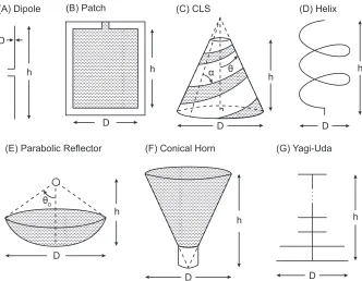
α θ
D
h h
D
(A) Dipole (C) CLS
h
D (B) Patch
D h (D) Helix
θ0
D
h (E) Parabolic Reflector
h
D (F) Conical Horn
h
D (G) Yagi-Uda
Figure 2.2: Geometry of antennas chosen for the present study
good electromagnetic and structural performance as shown in [13,15]. The conical horn and Yagi-Uda antennas have been chosen for operation beyond the UHF frequency bands typically used on amateur CubeSats [45].
The space for the antenna design problem is defined here as the set of antenna geometries that result in acceptable electromagnetic performance at the desired operating wavelength,λ. Constraints on the design space are written as a function of antenna height, h, and diameter, D, as defined in Figure 2.2for each antenna in this study. For the half-wavelength dipole, there is a unique design for each wavelength,λ, with the height, h, given by,
h= λ
2 (2.3)
The length of the dipole is referred to here as the dipole height, for consistency with other antenna types.
For the patch antenna, operation as a broad-side radiator requires that,
{0.003λ <t<0.05λ} ∩ λ
3 <h<
λ
2
(2.4)
the conductors around the cone, α, is used. Typical constraints on these parameters, to achieve a directional radiation pattern, are,
{2◦<2θ <45◦} ∩ {45◦ < α <90◦} (2.5)
Given θandα, the upper and lower radii of the cone, and its height can then be interpolated from experimental data.
Constraints for the helix are derived from desired operation in the end-fire mode with circular polarization [47]. Operation at a given wavelength depends on the diameter, conductor pitch, and number of turns of the helix, which can be re-expressed in terms of the diameter and height only,
D=λ
π
∩
3λ 4 tan 12
◦ <
h<20λtan 14◦
(2.6)
Geometries for the conical horn antenna and the parabolic reflector are defined to minimize antenna losses [47]. For the horn,
tan 5◦< D
2h <tan 30
◦
∩ (
h2=
D2
3λ
2 −
D
2
2)
(2.7)
For the reflector,
{0.65< ap <0.80} ∩ {2λ < D<50λ} (2.8)
where ap is the aperture efficiency, used here as explicit constraints on reflector height are too complex.
Finally, to achieve a directional radiation pattern, the Yagi-Uda array is typically designed such that [48],
{0.45λ <D<0.49λ} ∩ {0.3λ < h<6λ} (2.9)
2.3.2
Structural Architectures and Packaging Schemes
Structural architectures that allow efficient packaging exist for all of the above antennas as described in Section 1.1. Here, we focus on several schemes developed specifically for CubeSats in order to demonstrate the methodology. A simple architecture, suitable for the dipole antenna, is a single mechanical hinge supporting a stiff conducting element (Figure 2.3(A)). The hinge allows the con-ducting element to be folded parallel to the wall of the CubeSat. A simpler and popular alternative is themetallic tape-spring (i.e., a structure similar to a tape measure) that is elastically bent near the root to fold the rest of the tape spring parallel to the CubeSat, as in [25] (Figure2.3(B)). Tape springs can also be used to fold linear arrays including Yagi-Uda antennas [49].
non-conducting structural helices connected to non-conducting helices by scissor joints. This structure behaves as a helical pantograph [14], and hence has a soft deformation mode that allows axial compaction (Figure 2.3(C)). Alternatively, helical conductors can be supported at the base and compacted axially via rotation, resulting incoiling of the conductors around the base, as in [7,50] (Figure 2.3(D)). Another approach uses dual-matrix composite shells, made from laminated thin sheets of continuous quartz fibers embedded in two different plastic materials – a stiff epoxy resin and a soft elastomer – that support a set of embedded conducting elements [15]. The regions with soft elastomer matrix form hinges arranged according to an origami fold pattern that allows the shells to be folded tightly without damaging the fibers. Compaction in a single direction can be achieved using the z-folding pattern (Figure 2.3(E)) and compaction in two directions using the Miura-Ori origami pattern.
Parabolic reflector antennas require unique packaging schemes due to the doubly curved surface of the main dish. Typically these consist of a mesh conductor shaped by supporting curved ribs. The ribs can berigid with several hinges allowing them to fold alongside a central hub supporting the antenna feed (Figure 2.3(F)) [5]. Alternatively, the ribs can be elastic, allowing the mesh to wrap around the central hub using an origami packaging scheme (Figure2.3(G)) [8].
Table 2.1summarizes the antenna concepts used in the present study.
Hinge Tap e-spr
ings
Helical Pan
tographs
Z-F olded
Shells
Miura-Ori Shells
Coilable
Conductors
Hinged Ribs
Wrapp ed
Mesh
Dipole X X
Helix X X X X
CLS X X
Horn X X
Patch
Reflector X X
Yagi-Uda X
Table 2.1: Summary of antenna and deployment architectures c2017 IEEE
2.3.3
Predicting Antenna Performance
Having parametrized the geometry of the chosen antennas in terms of two common parameters,
(A) (B) (C)
(D) (E)
(F) (G)
Figure 2.3: Packaging schemes for CubeSat antennas (A) Dipole packaged using mechanical hinge [2] (B) Dipole packaged using tape springs [6] (C) Helix packaged using helical pantograph [14] (D) Helix packaged using coilable conductors [7] (E) CLS packaged using dual-matrix composite shell [15] (F) Reflector packaged using hinged ribs [5] (F) Reflector packaged using mesh wrapping [8]
experimental data [46]. The fractional bandwidth for the horn is derived from the performance range of commercially available antennas. The results are summarized in TableA.1in AppendixA. It is important to note that the electromagnetic performance of the chosen antennas depends also on non-geometric parameters, including material properties, feeding technique, and various other factors. However, in an initial design it is acceptable to predict performance based only on geometry; making specific, although preliminary, assumptions about these various effects is sufficient.
volumes in the deployed and folded configurations.
A summary of the equations used to compute structural performance is presented in TableA.2
in Appendix A. The fundamental frequency of vibration of each antenna has been approximated using analytic equations available in [51]. The packaged lengths and packaging ratios have been derived from [14], or computed directly. The structural metrics depend on the geometry as well as material parameters for which specific assumptions have been made based on existing antenna prototypes. These include the Young’s modulus, E, Poisson’s ratio, ν, linear/areal density, ρ, the number of panels in the origami packaging schemes,i and j, along the axis and the circumference of the antenna, and the Miura-Ori panel angle,φ, the conductor diameter, Dwir e, and the central hub diameter, Dhub.
2.3.4
Plots of Performance Metrics
The design problem is formulated as follows. Given a desired operating frequency for the antenna one calculates the corresponding wavelength. Then a set of n antenna concepts is selected, and m
performance metrics of interest are computed for them within nested forloops as a function of h
and D, as illustrated in Figure 2.4. The limits hmin, hmax, Dmin, and Dmax are computed for each antenna concept using constraints in Section2.3.1, and the metrics are evaluated using equations in TablesA.1 andA.2. Note that this is a brute-force approach, which can be sped up only through coarser discretization of the range of h and D for each antenna. A more efficient algorithm can be developed in the future to accommodate larger design spaces.
for concepts
i = 1:n
for metrics
j = 1:m
for
hmin:hmax
for
Dmin:Dmax
Compute metric
i
Plot metric vs.
h and D
Figure 2.4: Algorithm for estimating antenna performance
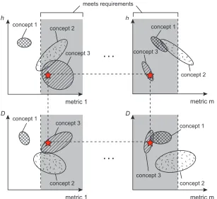
The algorithm in Figure 2.4generates the set of plots following the schematic shown in Figure
2.5; the layout of which is inspired by Ashby’s quad-charts [43]. The plots in the top row show the range of each performance metric that can be achieved, for each antenna, by varying the antenna height. Similarly, the plots in the bottom row show the effects of varying the antenna diameter. For each antenna concept, the locus of performance is shown as an ellipse, although the region may be non-convex or disjoint.
concept 1
concept 2
concept 3 h
metric 1
concept 1
concept 2 concept 3 D
metric 1
concept 1
concept 2 concept 3
D
metric m
concept 1
concept 2 concept 3
h
metric m
. . .
. . .
meets requirements
Figure 2.5: Schematic of design charts for comparing antenna performance
region of antenna performance that satisfies requirements prescribed for that metric. Those parts of the elliptical loci that lie within the shaded region represent design geometries that satisfy the requirements for that metric. By looking across several plots, as well as up and down, designers can find subsets of the design space that meet the requirements on all metrics. Thus, the final result is a set of antenna geometries, parameterized in terms of h and D, that are capable of meeting all requirements. This set can be used for a follow-on, detailed optimization. Furthermore, the design charts can be used to compare the performance of various antenna concepts to each other across a wide range of metrics.
2.4
Preliminary Design Tool
and electromagnetic performance evaluation. Thus, the tool reduces the selection and comparison time in the preliminary design stages.
Figure 2.6: Concept selection tool input screen c2017 IEEE
2.5
Case Studies
Several case studies of the design of deployable CubeSat antennas are presented here to demonstrate the advantages of the proposed methodology.
2.5.1
UHF Antenna Design
A case study of a UHF antenna operating at 450 MHz is presented to demonstrate the methodology. Furthermore, this case study is used to compare the performance of several concepts packaged using dual-matrix composites against COTS antennas. The antenna concepts compared are:
1. Dipole packaged using a mechanical hinge
2. Helix packaged using coiling of conductors
3. CLS packaged using z-folding of dual-matrix shells
4. Horn packaged using z-folding of dual-matrix shells
The following requirements are prescribed on the design:
2. Fundamental structural frequency higher than 0.1 Hz
3. Packaged antenna fitting in a 12 3U CubeSat volume (30×10×5 cm3)
4. Maximized bandwidth
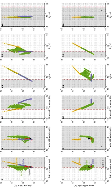
The requirements define a coupled electromagnetic and structural design problem appropriate for the methodology presented above. The geometric constraints on height and diameter are calculated from Equations2.3, 2.6,2.7, and 2.5, respectively, for the four antennas and are given in column 2 of Table2.2. The gain, fractional bandwidth, fundamental frequency, and packaged dimensions are computed from the equations in TablesA.1andA.2for this range of geometric parameters. These metrics are plotted against the antenna geometry as described in Section 2.3.4 and the result is shown in Figure2.7.
Concept Original Design Space (m) Optimization Space (m)
Dipole h=0.33 and D=0.025 Does not meet requirements Single Helix 0.012<h<3.32 andD=0.21 0.22<h <0.27 and D=0.21 Conical Horn 1.73<h<65.53 and 2.00<D<11.47 Does not meet requirements CLS 0.18<h<23.40 and 0.13<D<2.27 0.18<h <0.27 and 0.20<D<0.30
Table 2.2: Design and optimization spaces for UHF case study c2017 IEEE
To select specific antenna architectures that meet all requirements, one starts from plot A1, top-left in Figure 2.7. This plot identifies designs meeting the gain requirement; hence the region with gain higher than 5 dB (3.16 dimensionless) is shaded gray in the plot. The locus for the dipole antenna (which is a single point) falls outside the shaded area, indicating that it does not meet the gain requirement. Note also that the entire locus for the conical horn antenna falls inside the shaded area, hence it meets the gain requirement. Regarding the loci for the single helix and the CLS, only subsets fall within the shaded area. The height ranges corresponding to these subsets identify viable CLS antennas, with any height, and helical antennas with 0.22<h<3.32 m.
Dipole
Helix
Horn
CLS
Antenna Height (m)
Gain (dimensionless) A1 10 5 10 0 10 5 10 2 10 1 10 0 10 1 10 2 Dipole Helix Horn CLS
Antenna Diameter (m)
Gain (dimensionless) B1 10 5 10 0 10 5 10 2 10 1 10 0 10 1 10 2
Fractional Bandwidth (%)
A2 10 0 10 2 10 4 10 2 10 1 10 0 10 1 10 2
Fractional Bandwidth (%)
B2 10 0 10 2 10 4 10 2 10 1 10 0 10 1 10 2
Structural Frequency (Hz)
A3 10 5 10 0 10 5 10 2 10 1 10 0 10 1 10 2
Structural Frequency (Hz)
B3 10 5 10 0 10 5 10 2 10 1 10 0 10 1 10 2 L1 (m) A4 10 2 10 0 10 2 10 2 10 1 10 0 10 1 10 2 L1 (m) B4 10 2 10 0 10 2 10 2 10 1 10 0 10 1 10 2 L2 (m) A5 10 2 10 0 10 2 10 2 10 1 10 0 10 1 10 2 L2 (m) B5 10 2 10 0 10 2 10 2 10 1 10 0 10 1 10 2 L3 (m) A6 10 3 10 2 10 1 10 2 10 1 10 0 10 1 10 2 L3 (m) B6 10 3 10 2 10 1 10 2 10 1 10 0 10 1 10 2
constraints are given by plot A6.
Analysis of the first row of plots in Figure2.7has led to the conclusion that the dipole and conical horn cannot meet all requirements. At this point, an analysis similar to that described above, but using the bottom row of plots in Figure 2.7, provides the range of viable diameters for the helix and CLS. The outcome of the analysis is theh andDranges meeting all requirements, presented in column 3 of Table2.2. It can be observed that these ranges are orders of magnitude smaller than the original design space. At this point detailed simulations can be carried out to complete the design optimization.
Antenna designs generated independently via numerical simulations in ANSYS HFSS for this case study are denoted by red and black markers in Figure 2.7 for the helix and CLS antennas, respectively. A good agreement is seen between the performance of these and the designs that are proposed by the methodology here.
This case study has demonstrated that dual-matrix composites can enable the packaging of a CLS antenna in small CubeSat volumes, a concept not previously implemented. Furthermore, plots A2 and B2 in Figure2.7show that the CLS packaged using dual-matrix composites can achieve higher bandwidths. Therefore, it has been shown that dual-matrix composites can outperform existing concepts and should be studied further.
2.5.2
Ka-Band Case Study
A second case study demonstrating the preliminary design of a deployable antenna operating at 30 GHz (Ka-band) is shown here. The Ka-band has the potential for higher bit rates and smaller antenna sizes and would be appropriate for deep space CubeSats [5]. However, it is also known to be susceptible to rain attenuation and requires higher surface accuracy than antennas designed for the commonly used UHF-band for low earth orbit CubeSats. The case study illustrates the use of the proposed concept selection methodology to explore a new design space and identify constraint satisfying concepts. The antenna concepts compared are:
1. Helix packaged using helical pantographs
2. CLS packaged using z-folding of dual-matrix shells
3. Horn packaged using z-folding of dual-matrix shells
4. Parabolic reflector packaged using hinged ribs
The following constraints are placed on the design:
1. Maximum gain above 20 dB
3. Packaged antenna fits in a 1/2 1U CubeSat volume (10×10×5 cm3)
4. Design maximizes bandwidth
Following the methodology described in Section2.3, design space limits are computed using Equa-tions2.5– 2.8and the performance is estimated using TablesA.1and A.2. The results of the case study are generated using the tool in Section 2.4and are plotted in Figure 2.8. Starting from the top left corner of the chart (plot A1), one can select antenna heights for each concept which meet the gain requirement (i.e., ones in the shaded region with gain greater than 20 dB). It is evident that the entire loci of performance for both the helix and CLS antennas lie outside this region and hence cannot meet the gain requirements. However, from the performance loci for the horn and reflector one can see that there are designs that achieve the desired gain. In particular, horn antennas with
h>6.0 cm and reflectors with h>1.1 cm meet the requirement.
Moving to the right, one can repeat the same process for plots A2–A6, obtaining designs that meet the bandwidth, frequency, and packaged volume requirements. As no quantitative requirement has been specified on the bandwidth, no new constraints can be derived from plot A2. However, out of the remaining concepts, it can be seen that the horn maximizes bandwidth. From plot A3, it is evident that all concepts lie in the shaded region and can meet the fundamental frequency requirements. Plots A4 – A6 show that not all horn and reflector designs can be packaged in the required volume. From plot A4, one can get that h <9.5 cm for the horn andh <16.0 cm for the reflector. Plot A6 imposes a further constraint that h<14.5 cm for the reflector. A similar process is repeated with the bottom row of the chart (plots B1 – B6) to find antenna diameters that meet all requirements. This results is a narrow set of constraint-satisfying geometries as summarized in Table2.3. The initial design space has been reduced by at least an order of magnitude and the helix and CLS antennas have been ruled out as possible concepts as they cannot meet gain requirements.
Concept Initial Design Space (cm) Optimization Space (cm)
Helix 0.2<h<4.0 andD=0.3 Does not meet requirements CLS 0.3<h<35.2 and 0.2<D<3.4 Does not meet requirements Horn 2.6<h<98.3 and 3.0<D<17.2 6.0<h<9.5 and 4.4<D<5.4 Reflector 0.6<h<31.0 and 2.0<D<99.9 1.1<h<14.5 and 4.0<D<50.0
Table 2.3: Initial design and optimization spaces for Ka band case study
Helix
Horn
Reflector
CLS
Antenna Height (m)
Gain (dimensionless) 10 5 10 0 10 5 10 4 10 3 10 2 10 1 10 0 Helix Horn Reflector CLS
Antenna Diameter (m)
Gain (dimensionless) 10 5 10 0 10 5 10 4 10 3 10 2 10 1 10 0
Fractional Bandwidth (%)
10 0 10 2 10 4 10 4 10 3 10 2 10 1 10
0 10 Fractional Bandwidth (%)
0 10 2 10 4 10 4 10 3 10 2 10 1 10 0
Structural Frequency (Hz)
10 0 10 5 10 10 10 4 10 3 10 2 10 1 10
0 10 Structural Frequency (Hz)
0 10 5 10 10 10 4 10 3 10 2 10 1 10 0 L 1 (m) 10 4 10 2 10 0 10 4 10 3 10 2 10 1 10 0 L 1 (m) 10 4 10 2 10 0 10 4 10 3 10 2 10 1 10 0 L 2 (m) 10 4 10 2 10 0 10 4 10 3 10 2 10 1 10 0 L 2 (m) 10 4 10 2 10 0 10 4 10 3 10 2 10 1 10 0 L 3 (m) 10 5 10 0 10 4 10 3 10 2 10 1 10 0 L 3 (m) 10 5 10 0 10 4 10 3 10 2 10 1 10 0 A1 A2 A3 A4 A5 A6 B1 B2 B3 B4 B5 B6
The next step in the design would involve detailed numerical simulations of the horn and reflector designs in the optimization space in Table2.3. This would be a much shorter process than if one started simulations from the initial design space without knowing if a particular concept could meet all requirements.
2.6
Conclusion
A methodology for the rapid preliminary design of deployable antennas for CubeSats aimed at reduc-ing design times of deployable antenna problems was proposed. Usreduc-ing a novel visual representation method of antenna performance consisting of a coordinated set of plots of antenna performance metrics against the antenna geometric parameters, it can easily address coupled electromagnetic and structural design problems. This approach enables direct comparison of antenna concepts and allows the designer to rapidly identify concepts which meet requirements and to narrow down the design space, before tackling the problem with detailed numerical simulations.
The design of an antenna operating at 450 MHz and another operating at 30 GHz is used to demonstrate the method. The technique eliminates antenna designs unable to meet requirements, thus achieving a reduction of the original design space by several orders of magnitude. The results agree well with antenna designs optimized using numerical simulations. Furthermore, this tool is capable of identifying concepts not previously considered for use on CubeSats – the CLS and horn antennas packaged using dual-matrix composites for the UHF and Ka-band, respectively.
Chapter 3
Dual-Matrix Composite Antenna
Prototype
3.1
Introduction
The design strategy devised in the last chapter allowed the preliminary evaluation of dual-matrix composites as a packaging scheme for CubeSat antennas. It was shown that, at least theoretically, these materials can be used to design very high gain, broadband antennas capable of fitting into small CubeSat volumes. Moreover, the versatility of the packaging scheme was demonstrated. Dual-matrix composites can be used to package a variety of antenna topologies – from the helix to the conical horn – and appeared to scale well from one operating frequency (UHF) to another (Ka-band). These are promising results, however, the functionality of a prototype antenna must be verified to validate these results in practice.
To demonstrate functionality, this thesis focuses on a dual-matrix antenna operating at UHF with its design subject to the requirements in the case study in Section 2.5.1. The UHF band was chosen as it is the predominant choice for amateur CubeSats in low Earth orbit. Furthermore, working at higher frequencies would require the fabrication of very small antennas. The UHF case study in the previous chapter identified the CLS as an antenna topology capable of meeting the specified requirements and at the same time maximizing bandwidth over the helix. The design chart in Figure 2.7placed the following constraints on the CLS geometry such that all requirements are met,
0.18<hC LS <0.27 m ∩ 0.20<DC LS <0.30 m (3.1)
In order to validate the dual-matrix approach as applied to the deployable antenna problem, the following chapter demonstrates antenna RF and structural functionality. Furthermore, experimental results are compared to simulations to enhance the accuracy of numerical models to be used for design of such structures in the future. Most importantly, the antenna’s capability to meet requirements prior to and after folding and instantaneous deployment is assessed.
3.2
Antenna-CubeSat Assembly
An assembly of the prototype antenna with a 6U CubeSat structure in which it can be stowed is shown in Figure3.1. The antenna consists of a shell with Astroquartz II (AQ)/epoxy panels and AQ/silicone hinges. The antenna functionality is achieved by embedding a thin phosphor bronze mesh in the composites shell. The composites laminates are made of a 6 ply [±30/0]s,pw layup, where the pw subscript indicates that each ply is plain-weave. A detailed overview of material properties is given in Chapter 4. When deployed, the antenna is supported outside of the CubeSat by a dual-matrix hinge (studied in detail in Chapter 5). The feeding network for the antenna is also shown with a balun circuit used to split the 50 Ω input to two 100 Ω feeds attached to the two arms of the antenna. Furthermore, traditional co-axial cables have been replaced by custom-designed flexible microstrip lines to enable folding of the feed cables within the antenna. The feed lines are soldered to the conductors at the apex of the cone and then clamped between 3D printed plastic parts conforming to the curvature of the antenna. Likewise, the antenna is attached to the deployable hinge via screws with curved 3D printed washers.
Dual-matrix composite CLS antenna 3D printed feed
line connection
3D printed antenna
support connection 6U CubeSat structure
Dual-matrix composite deployable hinge Flexible microstrip
feed lines
Balun feed circuit
l d α
1. Stowed Configuration
2. Hinge Deployed
3. Antenna Deployed
z
y
Figure 3.2: Steps in antenna deployment from CubeSat
Figure 3.3: Folding of dual-matrix antenna by flattening and z-folding
A schematic illustrating the antenna deployment is shown in Figure 3.2. It can be seen that the antenna deployment has been decoupled from the hinge deployment for simplicity and to improve the reliability of antenna deployment without jamming.
Figure 3.3 shows the folding process of the antenna prototype. The cone is folded using 12 AQ/silicone hinges running along its height. The antenna is first flattened and the z-folded to package inside of the CubeSat.
3.3
Prototype RF Performance
3.3.1
Antenna Geometry Optimization
A parametric study was conducted using the ANSYS HFSS finite element software to optimize antenna performance independent of the CubeSat. The parameters of interest of the CLS geometry are illustrated in Figure3.4, where h is the height of the cone, Dand D0 are the lower and upper diameters of the cone, respectively,θis the cone angle, andαis the conductor wrap angle. The CLS antenna has two identical conductors rotated 180owith respect to the cone central axis. For clarity, only a single conductor is shown in the figure.
α θ
D
h D
0
z
x y
Figure 3.4: Geometry parameters of interest in the design of a CLS antenna
In Chapter 2, the geometry has been parameterized in terms of h and D only, and this is sufficient to describe the geometry. For a given h and D, the upper diameter (or equivalently θ) and conductor wrap angle are selected to minimize loses [46]. The cone geometry and conductor geometry are related by,
D=D0exp φ
2πlnE F
(3.2)
where 2φπ is the number of conductor turns and the expansion factor for the conductor,E F, is defined as,
E F=exp
2πsinθ tanα
(3.3)
The expansion factor was kept constant in this study at E F = 1.75, selected using design data in [46]. A parametric study varyinghandDwas done independently of the preliminary design given in Section2.5.1. Table3.1summarizes the geometry of a few of the designs considered.
Parameter Antenna 1 Antenna 2 Antenna 3 Antenna 4
h (cm) 19.0 19.0 17.5 18.5
D(cm) 32.2 33.2 35.5 28.2
D0 (cm) 16.0 16.0 16.0 14.0
φ/2π 1.25 1.3 1.5 1.5
s 20.7 20.6 20 19.6
Table 3.1: Antenna geometries in parametric study
200 250 300 350 400 450 500 550 600
Frequency (MHz) -20
-15 -10 -5 0
s 1
1
(d
B)
Antenna 1 Antenna 2 Antenna 3 Antenna 4
-150 -120 -90
-60 -30
0
30
60
90
120
150 180
-5 0 5
Antenna 1 Antenna 2 Antenna 3 Antenna 4
(A) (B)
Figure 3.5: (A) Reflection coefficient of select antenna designs (B) Cut in the y-z plane of radiation pattern at 450 MHz
Parameter Antenna 1 Antenna 2 Antenna 3 Antenna 4
BW(%) 79 81 65 69
G(dB) 6.78 7.15 6.88 5.36
Table 3.2: Summary of key performance metrics for antenna geometries in parametric study
3.3.2
Antenna Position Optimization
Having optimized antenna performance, the interaction of the antenna with the metallic CubeSat was investigated. The following parameters were investigated, illustrated schematically in Figure3.2, to determine their effects of the antenna gain, backlobe radiation, and axial ratio (a measure of polarization): the angle of the antenna axis with respect to the satellite, α, the overlap length of the antenna and the hinge, d, and the presence of solar panels on the CubeSat. A summary of the variable dependences observed in simulations is shown in Table3.3.
Parameter Range Axial Ratio Gain Backlobe Radiation
d 2 cm<d <6 cm Proportional Inverse Inverse
α 10o < α <50o Inverse Proportional Inverse
Solar Panels N/A Proportional Inverse Inverse
Table 3.3: Correlation observed between antenna position and performance metrics
was selected such that the antenna cone generator is parallel to the CubeSat edge. In order to maximize gain and reduce backlobe radiation, an overlap ofd =2 cm was selected. Furthermore, a boom length ofl=20 cm was selected to fit the antenna into the CubeSat.
3.4
Antenna Feeding Network
The feeding network consists of a 50/200ΩAnaren B0205F50200AHF surface mountable balun, to balance a 50Ωinput into the two arms of the CLS antennas, and two 100Ωtransmission lines. The micrstrip lines have been designed to have 100 Ω impedance over the entire antenna bandwidth. This was achieved by using a Chebishev tapering pattern for the microstrip conductor and ground lines. The geometry of the design is shown in Figure3.6. The feed lines were manufactured by San Francisco Circuits. A 1 oz. copper conductor was patterned onto both sides of a 125 µm Kapton layer to function as the ground plane and conductive strip. Both sides were then covered by a 25µm polyimide coverlay to prevent oxidation of the copper.
171 mm 116 mm
57 mm 122 mm
54.36
mm 108.72
mm
5 mm 7 mm
14 mm 18 mm 0.3
mm 0.5 mm 1.9 mm 3.4 mm 8.3 mm 11 mm 15 mm
Kapton insulator and ground layer
Copper conductor (A)
(B)
ground conductor
coverlay Kapton layer
Figure 3.6: Geometry of flexible microstrip lines (A) Chebishev tapering (B) cross-section
300 400 500 600 700 800 Frequency (MHz)
-35 -30 -25 -20 -15 -10 -5 0
s1
1
(d
B)
Balun Cables
Figure 3.7: Reflection coefficient of feed network
while the cables have a slightly narrower bandwidth of 360 - 650 MHz, and may impede antenna operation at the lower frequencies.
3.4.1
RF Testing
The electromagnetic performance of the antenna prototype was measured at the Antennas and RF Lab facilities at the University of New Mexico. The reflection coefficient was measured using the PNA-X 5247A vector network analyzer from Keysight. Radiation pattern cuts and gain measure-ments were done in a 5.33×2.59×2.13 m3anechoic chamber. A photograph of the CubeSat assembly under test in this chamber is shown in Figure3.8. Unfortunately, the existing chamber was designed for measurements above 1 GHz and is too small for UHF applications. As a result, the radiation pattern measurements are not entirely in the farfield of the antenna but are sufficient to verify performance with small error.
Figure3.9compares the measured reflection coefficient and radiation patterns to those predicted in finite element simulations. When the antenna is fed using co-axial cables, the reflection coefficient shows good agreement with simulations and it can be seen that antenna operation is achieved between 300-650 MHz. No change ins11was observed after folding and deploying the antenna. Also shown is the reflection coefficient when the antenna is fed with the flexible microstrip lines. The reflection coefficient curve is significantly impacted and as predicted antenna operation is lost at lower frequencies. However, the antenna still shows good operation between 354 - 407 MHz and 425 - 650 MHz.
band-Figure 3.8: CLS antenna and CubeSat assembly mounted in anechoic chamber at the University of New Mexico for radiation pattern measurements
width. No change in performance was observed after the antenna was folded and instantaneously deployed.
3.5
Prototype Structural Performance
3.5.1
Prediction of Vibration Modes
-150 -120 -90
-60 -30
0
30
60
90
120
150 180
-5 0 5
y-z Cut Simulated Cut
(A) (B)
300 350 400 450 500 550 600
Frequency (MHz) 5
5.5 6 6.5 7 7.5 8
![Figure 1.3: (A) CubeSat tape-spring deployable antenna [6] (B) Helios UHF deployable antenna [7](C) Deployable CubeSat mesh reflector with compliant ribs [8] (D) Skynet 4 UHF antenna [9] (E)Spring back reflector antenna [10]](https://thumb-us.123doks.com/thumbv2/123dok_us/1127934.1141601/22.612.118.532.221.550/cubesat-deployable-deployable-deployable-cubesat-reector-compliant-reector.webp)
![Figure 1.4: Elastic fiber microbuckling on the compression side of a folded elastic memory compos-ite [11]](https://thumb-us.123doks.com/thumbv2/123dok_us/1127934.1141601/23.612.239.412.116.253/figure-elastic-ber-microbuckling-compression-folded-elastic-memory.webp)
![Figure 1.5: (A) Schematic of folding of a dual-matrix composite hinge (B) Folding of an origamicrane using carbon fiber composite reinforced with epoxy and silicone [12] (C) Concept for a conicalantenna packaged using dual-matrix composites [13]](https://thumb-us.123doks.com/thumbv2/123dok_us/1127934.1141601/24.612.203.441.72.362/schematic-composite-origamicrane-composite-reinforced-conicalantenna-packaged-composites.webp)

 Dipole packaged using tape springs [6] (C) Helix packaged using helical pantograph [14] (D) Helixpackaged using coilable conductors [7] (E) CLS packaged using dual-matrix composite shell [15] (F)Reflector packaged using hinged ribs [5] (F) Reflector packaged using mesh wrapping [8]](https://thumb-us.123doks.com/thumbv2/123dok_us/1127934.1141601/33.612.152.497.69.413/packaging-mechanical-pantograph-helixpackaged-conductors-composite-reector-reector.webp)