Few-cycle laser-driven electron
accelerators
Daniel E. C´
ardenas Armas
Few-cycle laser-driven electron
accelerators
Daniel E. C´
ardenas Armas
Dissertation
an der Fakult¨
at f¨
ur Physik
der Ludwig–Maximilians–Universit¨
at
M¨
unchen
vorgelegt von
Daniel E. C´
ardenas Armas
aus Caracas, Venezuela
Contents
Zusammenfassung xiii
Abstract xv
Introduction xvii
Publications by the author xxiii
1 The light source: Optical parametric synthesizer LWS-20 1
1.1 The Laser . . . 1
1.1.1 The synthesis . . . 1
1.1.2 Intensity contrast ratio . . . 4
2 Laser-plasma I 7 2.1 Laser-driven ionization mechanisms . . . 7
2.2 Single electron in a highly intense electromagnetic field . . . 8
2.2.1 Ponderomotive force . . . 12
2.3 Propagation of electromagnetic waves in plasmas . . . 14
2.3.1 Underdense plasmas . . . 15
2.3.2 Overdense plasmas . . . 17
2.4 Particle-in-cell simulations (PIC) . . . 20
3 Laser wakefield electron acceleration 23 3.1 Basics of LWFA . . . 24
3.1.1 Wakefield generation and wavebreaking limit . . . 24
3.1.2 Electron injection into the wakefield . . . 25
3.1.3 Electron energy gain limitations . . . 27
3.1.4 Externally injected electron beams: shock front . . . 29
3.1.5 Beamloading . . . 30
3.2 LWFA experimental setup . . . 31
3.2.1 The LWFA chamber . . . 32
3.2.2 Shock-front generation . . . 34
3.3 LWFA experimental results . . . 36
4 Relativistic attosecond nanoplasmonics 59
4.1 Nano-solids basics . . . 60
4.1.1 Laser-plasma II: Light absorption and scattering in nano-solids . . . 60
4.1.2 Sub-cycle (non-ponderomotive) acceleration in plasmonic fields . . . 69
4.1.3 CEP effects in nanoplasmonics . . . 70
4.2 RANP experiment setup . . . 74
4.3 RANP experimental results . . . 75
4.3.1 Electron emission from a nano-target . . . 75
4.3.2 Intensity-dependent angular distribution . . . 81
4.3.3 CEP effects observed . . . 84
4.3.4 Discussion . . . 88
5 Conclusions and outlook 99 5.1 The LWFA electron phase-space evolution . . . 99
5.2 CEP-dependent emission of relativistic electrons from nanotargets . . . 100
5.3 Looking towards the future . . . 102
6 Data archiving 113
List of Figures
1.1 Laser scenario in 2017 . . . 2
1.2 Layout of LWS-20 . . . 3
1.3 Two-color-pumped OPCPA sequential amplification . . . 4
1.4 LWS-20 spectrum and temporal structure . . . 5
1.5 Measured LWS-20 intensity contrast . . . 6
2.1 Laser intensity vs. Tungsten ionization levels . . . 9
2.2 Electron kinetic energy in the laser field in the laboratory frame . . . 11
2.3 Sketch of ponderomotive force . . . 12
2.4 Scattering angle vs electron initial velocity fora0 = 4.5. . . 13
2.5 Scattering angle vs a0 for β0 = 0. . . 13
2.6 Group velocity dispersion in plasmas . . . 15
2.7 Plasma-scale length in solids . . . 19
2.8 Skin depth in solids . . . 19
2.9 Relativistic pseudo-transparency . . . 19
2.10 PIC simulations on RANP experiments . . . 21
2.11 PIC simulations on LWFA at a0 = 7 . . . 21
2.12 Electron spectrum from PIC simulations on LWFA at a0 = 7 . . . 21
3.1 Boat-driven wake. . . 23
3.2 One-dimensional wakefield in the quasi-static approximation at 8×1019cm−3 and τL = 5 fs. . . 26
3.3 LWFA phase-space diagram driven at 8×1019cm−3 and τ L = 5 fs. . . 27
3.4 Sketch of shock-front injection . . . 31
3.5 Experimental setup for the LWFA experiments . . . 32
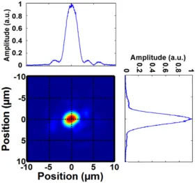
3.6 Laser focal spot used for LWFA experiments . . . 33
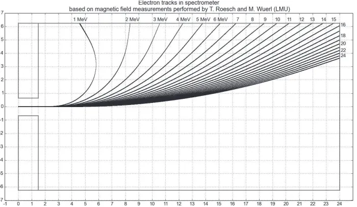
3.7 Dipole magnet dispersion used in the sub-5 fs LWS-20 experiments. . . 34
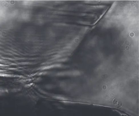
3.8 Visualization of the shock front on the sideview camera. . . 35
3.9 Measured density profile of a 300µm nozzle using shock front . . . 36
3.10 Illustration of the experimental setup used for the LWFA experiments . . . 37
3.11 Typical spatial properties of the electron beam produced in the LWFA ex-periments . . . 38
3.13 Peak energy of the electron spectrum for sub-10-fs laser pulses vs.
acceler-ation lengths for various electron densities . . . 40
3.14 Measured and predicted dephasing lengths . . . 42
3.15 Transmitted laser spectrum after the LWFA . . . 43
3.16 Rayleigh length determination for the LWFA experiments . . . 43
3.17 Measured longitudinal accelerating field for different densities . . . 44
3.18 Insight into the dephasing process . . . 46
3.19 Scheme of the phase-space evolution of the shock-front injected beam . . . 48
3.20 Details of shock-front injection through PIC simulations . . . 50
3.21 Comparison between experiments and PIC simulations for the 8 fs LWS-20 results . . . 51
3.22 Simulated electron spectra with an 8 fs laser pulse with a0 = 0.75 at a density of 4× 1019cm−3. . . 52
3.23 Simulated longitudinal field for 5 fs+20 fs2 . . . . 53
3.24 Simulated laser and wakefield evolution with 5 fs . . . 54
3.25 Simulated laser and wakefield evolution with 5 fs+20 fs2 . . . . 55
3.26 Simulated snapshots of the wakefield . . . 56
4.1 Schematic of charge separation in a nanoparticle with radius R0. . . 64
4.2 Radial electric field for particles of radius 50,200 and 500 nm . . . 66
4.3 Simulated radial electric field of nanospheres as function of time . . . 68
4.4 Electron current generated through tunnel ionization . . . 70
4.5 Electron trajectories in localized fields in the sub-cycle regime. . . 71
4.6 CEP effects in few-cycle lasers . . . 72
4.7 Asymmetry parameter A for the case of Fig.(4.6) . . . 73
4.8 Laser focal spot used for RANP experiment and determination of the Rayleigh length . . . 74
4.9 Gouy phase shift in RANP experiment . . . 75
4.10 Experimental setup for RANP experiment . . . 76
4.11 Alignment procedure of each target during the RANP campaign . . . 77
4.12 Average electron angular distribution in RANP experiment . . . 78
4.13 Typical electron angular distribution along the nanoneedle axis . . . 78
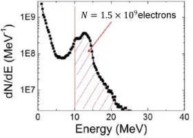
4.14 Electron spectrum measured in the RANP experiment . . . 79
4.15 Polarization sensitivity in the RANP . . . 80
4.16 Forces acting on the electron during its ejection from the nanotarget into vacuum. . . 81
4.17 Measured emission angle as a function of the laser peak intensity . . . 82
4.18 Measured emitted charge as a function of the laser peak intensity . . . 82
4.19 Typical shots for different laser peak intensities . . . 83
4.20 Measured and simulated asymmetry parameter AN as a function of the CEP. 85 4.21 Electron angular distribution as a function of the CEP. . . 86
4.22 Measured electron emission angle as a function of the CEP. . . 87
LIST OF FIGURES ix
4.24 First step of the electron acceleration mechanism . . . 89
4.25 Nanotarget surface field dynamics . . . 90
4.26 Electron energy evolution in real space during the first step . . . 90
4.27 Electron energy evolution through both acceleration steps . . . 92
4.28 Second step of the electron acceleration mechanism . . . 92
4.29 End of the electron acceleration in the second step . . . 93
4.30 Simulated electron energy as a function of a0 in RANP . . . 94
4.31 CEP sensitivity of the electron emission during the first step . . . 95
4.32 Simulated 2D asymmetry for one CEP . . . 96
4.33 Simulated 2D asymmetry as a function of the CEP . . . 97
5.1 Conclusion 1: Study of the electron dephasing in LWFA . . . 100
List of Tables
1 Costs of particle accelerators and other costly world-wide projects . . . xviii
Zusammenfassung xiii
Zusammenfassung
Die kollektive Bewegung von Elektronen im Plasma, ein Plasmon, besitzt ein damit verbundenes elektrostatisches Feld, welches den derzeit letzten Stand der Radiofrequenz-Beschleuniger-Technologie (50 MV/m) um mehrere Gr¨oßenordnungen (>103−104) ¨ubertrifft und r¨aumlich auf den Bereich einer Plasmawellenl¨ange (1-0.1)’sµm beschr¨ankt ist. Diese Plasmonen k¨onnen mittels ultrakurzer und hochin-tensiver Laserpulse durch verschiedene Kopplungsmechanismen erzeugt werden. In dieser Doktorarbeit werden zwei verschiedene Typen von Plasma-basierten Elektronenbeschleunigern vorgestellt, die von Laserpulsen mit wenigen Lichtzyklen getrieben werden: (i) die sogenannte Laser WakeField Accelera-tion (LWFA) durch Erzeugung von Volumenplasmonen in Plasma geringer Dichte (unterdicht); (ii) und die Generierung der sogenannten lokalisierten Oberfl¨achenplasmonen (localized surface plasmons, LSP) an der Schnittstelle zwischen nanome-trischem Plasma hoher Dichte (im s.g. ¨uberdichten Bereich) und Vakuum. W¨ahrend beide Prozesse durch Lichtpulse getrieben werden und der Gesamtenergiegewinn bis in den MeV Bereich reicht, ist die zugrunde liegende Physik grundverschieden. Im Falle der LWFA werden die Elektronen gefangen und in einer Plasmawelle beschleunigt (≈ 100 GV/m), die dem hochintensiven Laserpuls (2−6×10¹⁸Wcm−2) folgt, w¨ahrend dieser durch ein ionisiertes Heliumgas propagiert. Hingegen verst¨arken LSPs das einfallende Laserfeld (≥ TV/m) und fungieren als ein effizienter Photoinjektor von sub-fs relativistischen Elektronenbunch in das Laserfeld f¨ur eine anschließende Beschleunigung mittels Vacuum Laser Acceleration (VLA).
Die erste H¨alfte der Doktorarbeit behandelt die erste systematische Messung der Evolution des Elek-tronenstrahls im Phasenraum, die durch die Dephasierungsl¨ange charakterisiert ist. Die Studie wurde mit verschiedenen Elektronendichten 7−21 × 1019cm−3 f¨ur den τpuls<5 fs Lichtquelle, sowie f¨ur
gerin-gere Dichten (4× 1019cm−3) mit dem ¨alteren τpuls = 8 fs Laserpulsen durchgef¨uhrt. F¨ur diesen Zweck
wurde ein robuster externer Elektroneninjektionsmechanismus namens Shock Front verwendet, um die Beschleunigungsl¨ange durch die ¨Uberpr¨ufung der Injektionsposition in das Wakefield zu scannen. Auf-grund der starken Skalierung des Effekts, τpuls3 , wurden die gemessenen Dephasierungsl¨angen auf 60-300
µm begrenzt und finale Energiespit-zen von 6-20 MeV beobachtet. Shock-front-Injektion lieferte stabile und quasi-monoenergetische ∆E ≈ 3−5 MeV Elektronenstahlen und erm¨oglichte die Ver¨anderung der Parameter des Strahls, wie Ladung, Energiespitze, Divergent und relative Energiespreizung, erstmals mit hoher Ausl¨osung zu ¨uberwachen. Dar¨uber hinaus wurden neue Ph¨anomene wie die Entschleunigung und konsekutive Dephasierung identifiziert.
Abstract xv
Abstract
The collective motion of electrons in plasma, plasmons, has an associated electrostatic field which surpasses the current state-of-the-art radio-frequency accelerator technology (50 MV/m) by several orders of magnitude (> 103 −104); and a spatial dimension, the plasma wavelength, of (1−0.1)’s
µm. These plasmons can be excited by the force of an ultrashort high-intensity laser pulse by different coupling mechanisms. In this thesis, two different types of few-cycle laser-driven plasma-based electron accelerators are exposed: (i) the so-called Laser WakeField Acceleration (LWFA) by the excitation of volume plasmons in a low density (underdense) plasma; (ii) and the generation of so-called localized surface plasmons (LSPs) at the interface of a high density (overdense) plasma of nanometer size and vacuum. While both processes are driven by light pulses and the total energy gain scales up to the MeV range, the underlying physics are completely different. In LWFA, a few-fs electron bunch is trapped and accelerated in a plasma wave (≈ 100 GV/m) following the highly intense laser pulse, 2−6×10¹⁸Wcm−2, as the latter propagates through an ionized Helium gas. On the other hand, LSPs enhance instantaneously the incident laser field (≥TV/m) and act as an efficient photo-injector of sub-fs relativistic bunches into the laser field for subsequent acceleration in the Vacuum Laser Acceleration (VLA) scheme.
In the first half of this thesis, the first systematic measurement of the evolution of the electron beam in the phase-space, characterized by the dephasing length, is presented. The study was done for different electron densities 7 −21 × 1019cm−3 for the τpulse < 5 fs light source as well as at
lower densities, (4× 1019cm−3) with the older τpulse = 8 fs laser pulses. For this purpose, a robust
Introduction
The understanding of phenomena involving the transport of charge has over 2600 years of history. Since the observation of first electrostatic forces on amber (in Greek, ηλκτ ρøν, ”electron”) in 600 B.C. by Thales of Milet, the interaction of electromagnetic fields with charged particles has caught attention of scientists across centuries. From sheer curiosity, it has become one of the pillars of modern civilization.
Particle accelerators today: a
10
9$ infrastructure on
km
2size
Among many other technologies, the idea to accelerate electrons to generate secondary sources of radiation or discover new fundamental particles has been exaggeratedly appealing. It has applica-tions over various branches sweeping from science, industry and medicine [143, 31, 98]. Moreover, in 1979 the idea of a Laser electron Plasma-based Accelerator[144] (LPA) was conceived. This partially overlapped in time with the evolution of ultra-high power femtosecond laser technology. Chirped-Pulsed Amplification (CPA)[139] revolutionized the laser technology and allowed the generation of 10’s fs pulses with high peak power which soon reached the required intensities in the original LPA proposal, aboutIL≈1018Wcm−2. The laser intensity is determined by:
IL=
0cEL2
2 (1)
where, 0 and c are the vacuum permeability and the velocity of light in vacuum, respectively.
The alternative idea of a highly intense laser used for accelerating particles seems natural since intensities of 1018Wcm−2correspond to an electric field ofEL≈3TVm−1. As it will be described
in this work, acceleration of particles with the laser field itself is far from trivial. In order to circumvent this limitation, the original LPA idea takes advantage of the collective properties of gaseous plasmas and their capacities to sustain fields of the order Eplasma ≈ 100 GVm−1. The
Particle accelerator Cost (USD) Size (km)
CERN∗ (EUROPE) 7.5 G$ 10’s
SLAC∗ (USA) 350 M$ 3
Sirius∗ (Brazil) 400 M$ 0.5
Sesame∗ (Middle East) 79 M$ 0.1
Extreme Light Infrastructure+ (ELI) 750 M$ ≈0.01 (table-top)
Conventional Petawatt (PW) system+ 10 M$ ≈0.01 (table-top)
Other costly projects Cost (USD)
U.S. defense budget 800 G$
Project Apollo Space Program 25G$ Eradicate world poverty 175 G$
Country/Region GDP (USD)
European Union GDP 16 T$
U.S. GDP 18 T$
Brazil GDP 2 T$
Middle East GDP 1.5 T$
Afghanistan GDP 20 G$
xix
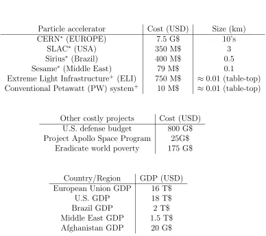
In order to get a good impression on how much effort is being put into particle accelerators, laser-driven and conventional ones, take a look at Table 1. From this table, here are some key points:
1. How much particle energy is enough? MeV, GeV or even TeV energy level. Different ap-plications require particular spectral ranges. From 100’s MeV level protons[113] and heavy ions [83] for cancer therapy. Moreover, TeV electron-positron or TeV protons collisions al-low new fundamental particles to be discovered, such as the Higgs Boson[1]. Current state-of-the-art accelerators are limited to maximum values about 50 MVm−1 before electrical breakdown. This automatically corresponds to acceleration lengths of TeV/MVm−1 →102 km. For this purpose, circular structures such as the Large Hadron Collider (LHC)[42] in CERN with a circumference of about 30 km are designed where the hadrons accelerates subsequently until it reaches the desired range.
2. The size of LPAs are mostly limited to the laser system size, the so-called table-top, since the acceleration itself takes place within an adult human’s hand. State-of-the-art reports have demonstrated GeV electrons within few centimeters [89]. A key advantage of LPAs is their compactness given by the large accelerating fields (≈100 GV m−1), about 104 higher than conventional radio-frequency based technology, such as CERN or SLAC.
3. The amount of money invested in building such accelerators is intuitively proportional to their size. Although cutting-edge-laser technology projects are quite expensive at the moment, such as ELI, the budget is far below the one used for big facilities such as CERN. Moreover, conventional PW systems are becoming routinely available, even more in the near future, thus lowering their selling price.
4. Particle accelerators have applicability in science, industry and medicine. In particular for the latter, radiation-based cancer therapy is already being implemented in several hospitals around the globe [117]. Furthermore, electron acceleration leads to secondary sources, such as broad band ultra-brilliant X-rays. A charged particle propagating in a circular geometry, such as a synchrotron loses E4kin
m4R per turn, where Ekin and m are particle kinetic energy
and rest mass, and R the radius of the accelerator. In the case of LHC at CERN, this “lost” energy is on the order of a few keV per proton and about 1% of the energy gain per round-trip due to its large circumference of 27 km. Yet, in the case of electronsme mp,
this photon emission is utilized for multiple X-ray scientific[82] and medical studies[141]. 5. The particle accelerator community is huge and its economical weight surpasses many
third-world economies. The budget to build one accelerator such as CERN is even comparable to the GDP of an entire country. This data is meant to transmit the reader the importance of this field and its huge technological future. Its worth is recognized by governments from different countries which are currently investing an incredible amount of money, about 0.1% of their GDP, in building them.
100’s pC at 100’s MeV energies, few milimeters to centimeters acceleration length and few fem-tosecond bunch duration. The generation of such ultrashort electron pulses is intrinsic to the LWFA mechanism, since the bunches occupy a fraction of the plasma wavelength which spans from few to many 10’s µm. Nevertheless, the overall performance must fulfill extreme require-ments demanded by big-impact applications such as an X-ray synchrotron or a free-electron laser (XFEL). Reducing the costs and size is not enough. LPA’s electron parameters such as absolute energy spread, charge, stability, among others, must be significantly improved. In particular, seeding an XFEL[50] require monochromaticity1% energy spread, high charge≈1 nC within 0.1% of the spectral bandwidth at 1 GeV[98], 10’s fs pulse duration, small normalized emmitance (<1nm)[100], reproducibility, etcetera. The injection into the accelerating structure has become a fundamental step for meeting these demanding criteria. Among different external injection mechanisms[25, 47], shock-front injection[131] has gained relevance within the laser-accelerator community due to the stability, tunability and absolute energy spread, reaching few per cent [14]. In the family of laser accelerators, LWFA would be the experienced big brother. Still the fact that EL≈3TVm−1 at 1018Wcm−2 (orders of magnitude higher than in LWFA), makes the
idea of accelerating the electrons directly with lasers very appealing. Vacuum Laser Acceleration (VLA) has been largely studied since its original proposal in 1995 [40]. Surfing this field seemed rather complicated, for a relativistic (>MeV) electron bunch should be injected within a half laser cycle. Thus, LWFA is to femtosecond as VLA is to attosecond. Via exotic interactions with solids, VLA made it to the spotlight in 2015 [147] by generating a 20-MeV attosecond electron bunch train. Nevertheless, no mention of the expected fields ofO(TVm−1) was made nor insight
into the injection mechanism was described. Solid further steps in this promising direction are taken in the second half of this work.
High field lasers today: still a
10
7$ infrastructure on 10
m
2size
LPA technology could be competitive, among many things, for its compactness and lower costs. Nevertheless, only highly intense and expensive 106$ TW-PW laser systems with 10’s m2 size can drive the acceleration. Can we actually further reduce the required laser systems? Once again, the answer lays in collective motion of electrons.
xxi
realize electron ”nano accelerators”. State-of-the-art novel nJ-laser-driven mini-accelerators have reached accelerating fields up to a few-GVm−1 [65] and kinetic energies in the keV level [71, 37]. In this work, we examine to which extent can few-TW pulses be enhanced by a target of 100’s nm size at unprecedented intensities and its final impact on the electron emission. This topic will be referred to as Relativistic Attosecond Nanoplasmonics (RANP).
Structure of this work
Chapter 1: The light source
The first chapter describes the light source utilized in this thesis, the Light Wave Synthesizer 20 (LWS-20). The laser parameters are not only described in terms of energy and pulse duration, but the reader understands the uniqueness of LWS-20 and is able to identify its pioneering position in the context of relativistic laser plasma physics in the near single-cycle regime.
Chapter 2: Basics of laser-plasma interactions
The second chapter is a review of the most relevant laser-plasma interactions. Here, general concepts involving the two experiments explained in this work are introduced. These include ionization mechanisms and single electron motion in the laser field, as well as the optical prop-erties regarding propagation of light in overdense and underdense plasmas. Finally, some basic notions of Particle-In-Cell simulations are presented, along with examples involving the exper-imental work exposed in this thesis. This chapter provides the knowledge to interpret and understand the experimental results discussed in chapter 3 and 4.
Chapter 3: LWFA experiment
Firstly, this chapter provides a short introduction of the laser wakefield accelerator concept, including the wakefield generation and some electron injection mechanisms as well as the main limitations of the maximum obtainable electron energy and their corresponding scaling in terms of the laser parameters, in particular the electron dephasing. The rest of the chapter corresponds to the first experiment this thesis deals with: a detailed analysis of the phase-space evolution of the electron beam during its acceleration in the laser wakefield. This evolution is characterized by the dephasing length, about 60-300 µm for the current sub-5 fs LWS-20 version and the old 8 fs one.
Chapter 4: RANP experiment
Firstly, this chapter provides a short and more detailed introduction about laser-plasma inter-actions in solids, including absorption mechanisms as a function of the laser intensity and the plasma scale length. Moreover, the scattering of light by targets whose dimensions are smaller than the optical wavelength, ≈ 100’s nm at low intensities is also presented. Furthermore, a historical background about the electron emission from these nanotargets as a function of the exact shape of the laser electric field using near-IR laser pulses is shown as well as the study of the sub-cycle emission regime at mid-IR driving conditions. This knowledge, combined with Chapter 2, should suffice to understand the experimental observations. The rest of the chapter corresponds to the second experimental campaign of this thesis: the attosecond emission of relativistic electrons from nanotargets in the near single-cycle regime.
Chapter 5: Conclusions and outlook
Publications by the author xxiii
Publications by the author
The experiments reported in this thesis were performed using the LWS-20 laser system at the Max Planck Institute for Quantum Optics. In these experiments, the author played an active role in terms of laser performance, work in laboratory and interpretation of the collected data. Moreover, the author also collaborated in other scientific works presented below.
• D.E. Cardenas, S. Chou, J. Xu, L. Hofmann, A. Buck, K. Schmid, C.M.S. Sears, D.E. Rivas, B. Shen, and L. Veisz. Energy limitation of laser-plasma electron accelerators. Sub-mitted to New Journal of Physics. (2017)
- The author contributed to build the experimental setup and was largely responsible for the electron diagnostics. The experimental data was collected by the author in collabora-tion with S.C. and L.H. The author evaluated the data obtained with the sub-5 fs LWS-20 laser, re-evaluated the data obtained with the 8 fs LWS-20 and wrote the manuscript with the input from L.V. and S.C. plus other co-authors.
• D.E. Cardenas, T.M. Ostermayr, L. Di Lucchio, L. Hofmann, P. Gibbon, J. Schreiber and L. Veisz. Sub-cycle relativistic nanophotonics. Submitted toNature Photonics. (2017) - The author designed and built the experimental setup with collaboration from L.H. The data was collected by the author with T.M.O., who participated in the experimental cam-paign. The author performed the complete analysis of the experimental data, evaluated the results obtained from simulations and wrote the manuscript with suggestions from L.V. and other co-authors.
• D.E Rivas, A. Borot, D.E. Cardenas, G. Marcus, X. Gu, D. Herrmann, J. Xu, J. Tan, D. Kormin, G. Ma, W. Dallari, G. Tsakiris, I. F¨oldes, S. Chou, M. Weidmann, B. Bergues, T. Wittmann, H. Schr¨oder, P. Tzallas, D. Charalambidis, O. Raszkazovskaya, V. Pervak, F. Krausz, and L. Veisz. Next Generation Driver for Attosecond and Laser-plasma Physics. Accepted inScientific Reports (2017).
• S. Chou, J. Xu, K. Khrennikov, D.E Cardenas, J. Wenz, M. Heigoldt, L. Veisz, and S. Karsch. Collective deceleration of laser-driven electron bunches. Physical Review Let-ters. 117, 144801 (2016).
- The author performed simulations regarding the evolution of the electron beam using General Particle Tracer.
• M. Aladia, R. Bollaa, D.E. Cardenas, L. Veisz, and I. B. F¨oldes. Cluster size distributions in gas jets for different nozzle geometries. Submitted to Journal of Instrumentation
(2017)
Chapter 1
The light source: Optical parametric
synthesizer LWS-20
Laser-matter interactions are divided in two major fields with two completely different perspec-tives: attosecond science and laser-plasma physics. Nowadays, high-peak power lasers provide relativistic intensities beyond 1018Wcm−2 and can be utilized to accelerate particles such as electrons[98, 41]. Highly intense lasers started to develop interesting new physics when the gen-eration of intense attosecond light pulses from solid targets was suggested [103, 106]. On the other hand, low-energy near single-cycle pulses have proved to control the electron currents in dielectrics[129] by the force of light in the attosecond range [59, 10]. Provided the high sensitivity of the electronic response to the exact shape of the incident field, sub-2 cycle lasers can trigger a final asymmetrical emission[110, 165] which exploits the applicability of these sources. Further-more, highly interesting and exotic scenarios are expected when these short pulses are applied at relativistic intensities. Next generation of sub-fs particle sources such as isolated high-yield MeV electron[36, 91] or 100 eV photon[151, 94] bunches could be generated if such an asymmetry is exploited. State-of-the-art multi-10 mJ few-cycle broadband light sources [16, 78, 156], such as ours, based in chirped nonlinear amplification are filling this gap in the laser world scenario. In particular, our laser, the sub-5 fs Light-Wave Synthesizer (LWS-20) is an unique system which connects the attosecond science and the high-energy field as shown in Fig.(1.1). When focused to almost the diffraction limit w0 ≈ λL = 740 nm with an unprecedented temporal intensity
contrast, extreme interactions occur where the electrons reach 99%c in less than 2 optical cycles.
1.1
The Laser
1.1.1
The synthesis
Figure 1.1: Laser scenario in 2017. Typical laser systems corresponding to relativistic plasma physics are highlighted in red: ATLAS [14], Lund Laser Center (LLC) [35], 20 TW VEGA system [126], JETi200 [75], Astra-Gemini [70], the Petawatt system at the Gwangju Institute of Science and Technology [80], the BELLA project [88], the J-KAREN system [3], the Texas Petawatt System (TPS) [52] and the PHELIX laser [4]. Find a complete review on Petawatt lasers in [32]. Some examples of few-cycle sub-mJ laser systems working in the attosecond field are marked in blue: Cavalieri et al.[20], Zherebtsov et al.[164] and down to single-cycle regime from Goulielmakis et al.[59]. Single-cycle pulses with higher energies (mJ-level) are becoming available as well, as reported by Gu´enot et al.[60]. Finally, few-cycle multi-10 mJ lasers such as: the Petawatt-Field Synthesizer (PFS) [78] and the work of Budriunas et al. [16], together with the sub-2 cycle LWS-20 [156] used in this thesis, fill the gap between these research areas. As observed in the figure above, the LWS-20 is the few-cycle most powerful laser in the world.
short pulse durations τpulse. Here is where the synthesis takes place[59] and gives name to our
laser system. Different spectral components are coherently mixed, yet each one is independently controlled in terms of amplitude and phase. Furthermore, our amplification scheme is scalable to higher energies.
1.1 The Laser 3
magnitude[22, 155].
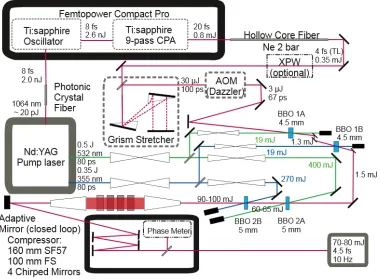
Figure 1.2: Layout of LWS-20
The LWS-20 layout is shown in Fig.(1.2). The system is born in a 80 MHz few-nJ few-cycle Ti:Sa oscillator which seeds simultaneously the front end (60%) as well as the pump laser (40%). The first part of the front end is a commercially available CPA-based Ti:Sa system delivering light pulses centered at 800 nm with 1 mJ and 22 fs pulse duration at 1 kHz repetition rate (Femtopower Compart Pro, Femtolasers GmbH). These pulses are sent into a Neon-filled hollow-core-fiber for spectral broadening via self-phase-modulation [23]. Immediate compression down to sub-5 fs using chirped mirrors is required when the Cross-Wave Polarizer (XPW) is used[76]. Using XPW or not, the pulses are then temporarily stretched in a GRISM (a combination of a prism and grating) ”stretcher” [146] up to 100 ps and directed straightaway to a acoustic-optical programmable dispersive modulator (DAZZLER, Fastlite Ltd.). The final seed (few-µJ) pulse duration is about 60 ps before the amplification.
Figure 1.3: Two-color-pumped sequential amplification, spanning a spectrum from 580 to 1020 nm with an energy of about 100 mJ. Figure obtained from [156].
region. Visible spectral region (580-700 nm) and near-IR (700-1020 nm) are amplified separately and consecutively by the 355 nm and the 532 nm pump, respectively. After the last stage, a final energy of about 100 mJ is reached, as shown in Fig.(1.3). In order to avoid strong nonlinearities in the silica crystals, the still chirped pulses are expanded to a size of approximately 5 cm’s and then compressed in 160 mm-long SF57 and 100 mm fused silica down to 100 fs. A deformable mirror and a wavefront sensor in a closed loop configuration were installed before the compressor chamber to optimize the small wavefront aberrations≈50 nm in order avoid major energy losses on the focal plane. Four chirped mirrors are in charge of the final compression in vacuum down to sub-5 fs, see Fig.(1.4), and the pulse is finally sent to the experiments with an energy 70 mJ. For complete temporal characterization, the carrier envelope phase (CEP), ϕCEP, which is the
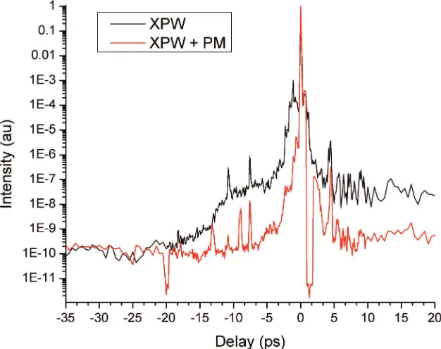
offset between the optical phase and the maximum of the wave envelope of an optical pulse, must be measured. For this purpose, a small portion of the laser beam is taken from the main driver through a 5 mm diameter silver mirror coated on a 2 µm thick pellicle (National Photocolor) and sent to single-shot stereo phasemeter[161]. In this way, although the waveform shape is not controllable, it is measurable shot-to-shot.
1.1.2
Intensity contrast ratio
1.1 The Laser 5
Figure 1.4: Left: The sub-5 fs LWS-20 spectral power density and phase. Right: Tem-poral structure of the Fourier-limited and compressed LWS-20 pulse.
system. However, picosecond-gated pumping to a final maximum gain of 105 compensates this limitation. The small gain in OPCPA is a nonlinear function of the laser intensity,G∝e
√
Ipump. Thus, strongly-pumped high-gain OPCPA, G ≈ 105 in only one channel would lead to strong AOPF[81], since IAOPF ∝ G. For this purpose, LWS-20 possesses two sequential channels with
gains of 103 in and 102, respectively, for each color pump as seen in Fig.(1.3). In this way, control over the gain andIAOPF is of extreme relevance when designing each OPA stage.
Chapter 2
Laser-plasma I
The light source used in this work was already introduced in the previous chapter. Now, in this chapter we explain briefly the interaction of light with matter, and by matter we mostly mean plasma, a mixture of free electrons and immobile background ions. For this purpose, we first start by how matter is ionized under such strong fields (sec.2.1). Subsequently, we describe how a single electron is influenced by an electromagnetic wave (2.2) and immediately see that by focusing highly powerful multi-TW lasers to almost the diffraction limit λL, instantaneous
energies of multi-MeV are reachable within a half laser cycle. We analyze the scenarios of laser acceleration in vacuum (VLA) in sub-sec.??as well as ponderomotive acceleration in sub-sec.2.2.1. In sec.2.3, we will review various effects about the propagation of laser fields in underdense plasmas (sec.2.3.1) from analyzing the index of refraction. We will point important concepts and phenomena regarding ”propagation” in overdense plasmas, such as solid-targets (sec. 2.3.2), serving as a prequel to sec.4.1.1 in the fourth chapter. Lastly, we will comment on a well-known computational tool scientists use to understand better the complicated physics beneath all these interactions in sec.2.4.
2.1
Laser-driven ionization mechanisms
Before deepening into the propagation of light in plasmas, such plasmas must be generated. A plasma is a medium where electrons and ions are moving freely. Particularly, in this work the plasma response is limited to the electron dynamics and the ions (Mion me) are assumed to
remain as a constant background. Laser-driven typical ionization mechanisms are determined by the Keldysh parameter γK =
p
Eion/2Up, where Eion is the ionization potential of a bound
electron andUpis the laser ponderomotive potential, i.e. the energy acquired by an electron within
the laser field as discussed later in 2.2. At low laser intensities, IL ≈1012W cm−2, γK 1, an
electron can absorb N photons N hν ≥eEion and surpass the binding potential. This is
multi-photon ionization (MI). At modest intensities, IL ≈ 1015W cm−2, γK 1, the mechanism is
Ion (Z∗) Eion (eV) Intensity (W cm−2)
He→ He+ 24.6 1.4× 10¹⁵
He+→ He+2 54.4 8.8× 10¹⁵
W+59→ W+60 2575 4.9× 10¹⁹ W+73→ W+74 69525 1.7× 1025
Table 2.1: Required intensity given by Eq.(2.1) to ionize different ions.
spontaneously. This type of ionization is referred to as barrier suppression (BSI). The threshold laser intensityIL,BSI for BSI to occur is [54]:
IL,BSI
W cm−2
≈4×10⁹(Eion[eV])
4
Z∗2 (2.1)
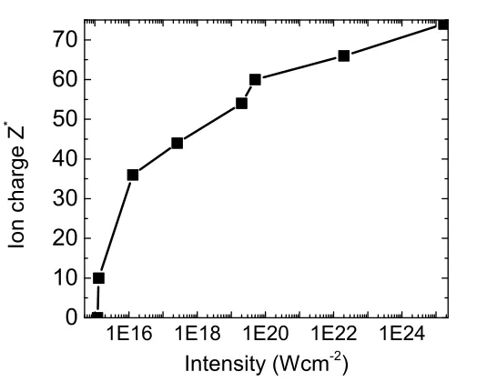
where Z∗ is the charge of the ionized atom. For instance, the required intensities to ionize some ions are shown in Table.(2.1). Typical intensities used in LWFA experiments, included the ones in this work, are on the order of 1018W cm−2. Moreover, most of the times the gas emanating from the nozzle is Helium. Full ionization thus occurs long before the main peak arrives at the interaction (see sec.1.1.2) and the assumption that laser light propagates in plasma is valid. Solid targets made of, for example Tungsten, are not completely ionized in the parameter range of current 80mJ LWS-20. Complete ionization of Tungsten W73+→ W+74 would require 1.7×1025W cm−2, or about 3 J of energy within 2 optical cycles focused to the diffraction limit, not reachable by any laser technology available nowadays. AtIL= 6×10¹⁹W cm−2, the electron
density in a Tungsten solid target would theoretically be, according to Eq.(2.1):
ne=Z∗ni=
Z∗NAρ
A , (2.2)
which after putting numbers for our case: Z∗ = 60, NA = 6.02× 10²³, ρ = 19.3g cm−3 and
A = 183.85, results in ne = 3.8× 1024cm−3. Thus, a fully ionized 400 nm diameter Tungsten
hemisphere containing 2×10⁹W+74ions would yield 25 nC.
2.2
Single electron in a highly intense electromagnetic
field
The propagation of any electromagnetic wave E(t), B(t) through any medium is ruled by the Maxwell equations [73]:
~
∇ ·E~ = ρ
0
, (2.3)
~
∇ ×E~ =−∂
∂tB,~ (2.4) ~
∇ ·B~ = 0, (2.5)
~
∇ ×B~ = 1
c2
∂ ∂t
~
E+µ0~j. (2.6)
2.2 Single electron in a highly intense electromagnetic field 9
1E16 1E18 1E20 1E22 1E24
0 10 20 30 40 50 60 70 I o n c h a r g e Z *
Intensity (W cm -2
)
Figure 2.1: Tungsten ion charge W+Z∗ as a function of the laser intensity according to
Eq.(2.1).
where 0 and µ0 are the vacuum permittivity and the permeability, respectively; c = 1/ √
0µ0
the speed of light in vacuum,ρ is the charge density and~j is the current density. The electricE~
and magnetic fieldB~, propagating with a wave vectork~L= ωcL~e, where ωL= 2λπc
L is the angular frequency, can be rewritten as a function of the vector potential A~ = A~0cos (ωLt−k~L·~x) and
the scalar potential φL:
~
EL(~x, t) =−
∂
∂tA~−∇~φL, ~
BL(~x, t) =∇ ×~ A.~
In laser-plasma physics, there are two main laser concepts which determine the regime of the interaction: intensityILand ponderomotive energy∝ ILλ2L. The intensity is the spatio-temporal
energy density. For a laser pulse of duration τL,I = Φ/τL, where Φ is the photon flux. For this
work, typical intensities of 1018−1020Wcm−2 were employed, leading to Φ ≈ 5× 10³ −5×
105Jcm−2, or 1014−1016photonsµm−2. The motion of a charged particle with a nonzero rest mass (an electron ofeandme, respectively) in vacuum under the action of the laser field is given
by the Lorentz and energy equations:
dγ~v dt =−
e me
(E~ +~v×B~),(Lorentz eq.), (2.8)
dγ dt =−
e mec2
(~v·E~),(Energy eq.), (2.9) where ~p=γme~v is the electron’s momentum and γ =
p
1 +|~p|2/(m
ec)2 is the gamma factor of
deduced that the quiver velocity of an electron within an electromagnetic half-cycle is given by:
vquiver = ωe ELm0e = e Ame0. For a linearly polarized field, the electron momentum in the transverse
plane p~⊥ equals the vector potential, A~. a0 ≡ A0/mec is commonly used to determine how
relativistic the electron becomes:
a0 = 0.854
p
IL[1018Wcm−2]λL[µm]. (2.10)
The mean kinetic energy of an electron in the reference frame at which the quivering motion of the electron is at rest may be considered as an internal energyW [104]. W is defined as:
W =mec2
h
(1+< a0 >2)1/2−1
i
(2.11) where ”< > ” represents cycle-averaging. This corresponds to < γL,quiver >=
p
1 +a2 0/2 →
βquiver = vquiver/c = 0.7, at a0 = 1 or 2.5 × 10¹⁸Wcm−2 using a 740 nm laser. The wiggling
is further quantified by the quivering amplitude lq = eE0/meωL2. The classical
ponderomo-tive potential Up = (eE0)2/4mω2L [112] corresponds to the energy of a quivering electron at its
oscillation frame at very low intensities, a0 1. At higher intensities, a0 1, many
laser-matter interactions are described as a function of a0. For instance, the electric field of the laser
E0 =a0/λL[µm]×3.21 TVm−1. In the laboratory frame, it can be further deduced that the
nor-malized momentum of an electron, originally at rest, under the influence of a linearly polarized electromagnetic wave will be determined by following expressions:
˜
py =a0cosφ (2.12)
˜
px= ˜py2/2, (2.13)
= a
2 0
4 [1 + cos 2φ], (2.14) ˜
pz= 0. (2.15)
where ˜p is the normalized electron momentum tomec and φ = ωLt−k~L·~x. Furthermore, the
corresponding gamma factor and the final kinetic energyEkin of the electron is just given by:
γL,lab= 1 + ˜px, (2.16)
Ekin= (γL,Lab−1)mec2 (2.17)
= a
2 0
4 [1 + cos 2φ]mec
2. (2.18)
The maximum energy gain under this scheme is then ∆E =mec2a20/2. From the formulas
above 2.18, we could obtain maximum energies Ekin ≈ 100’s keV and 10 MeV for a0 = 1 and
8, respectively. Is it really so easy to gain energy in a travelling wave? No! In fact, many controversy has come to this topic due to Lawson-Woodward theorem[87, 162] (LWT). It states that an electron traveling in a straight trajectory along the laser axis from z=−∞to z= +∞
with vz ≈ c gains no net energy throughout its path in the laser field. The theorem permits
acceleration if one of the following conditions is broken[54]:
2.2 Single electron in a highly intense electromagnetic field 11
-20 -10 0 10 20
0 8 16 -3 0 3 6 0 3 6
-20 -10 0 10 20
a
0
2
time (fs)
a
0
E
ki
n
(
M
e
V
)
Figure 2.2: Top: Electron kinetic energy Ekin acquired instantaneously from the laser in
the laboratory frame, using Eq.(2.18). Middle: Normalized vector potential a0. Bottom:
Normalized instantaneous intensity a2 0.
2. The electron is highly relativistic along the acceleration path, 3. no static or magnetic fields are present,
4. the interaction region is infinite, 5. ponderomotive forces are neglected.
between the classical quivering regime and the real VLA[147] is the sub-cycle, i.e. attosecond, injection of relativistic electron beams. In this regime, the electron bunch propagates trapped within two half-cycles of the laser field[149] while gaining energy. Although different theories have tried to address the VLA mechanism using different laser polarizations[40, 159, 158, 111,?], the final picture results in an energy gain in the ponderomotive potential well of the laser, even where “ponderomotive acceleration” is commonly referred to as a cycle-averaged process.
2.2.1
Ponderomotive force
The ponderomotive force originates from the finite spatio-temporal extension of the laser profile. Since ~a ≡~a(r), Taylor-expansion of the laser field in the transversal direction yields an extra nonlinear component in the force of the light on the electron: Fp =−mec2/γL∇(a2/2). A similar
expression is also deducible from Eq.(2.9). The ponderomotive force can be also understood as the light pressureIL/con a certain particle or target. This force pushes away the electrons from
the most intense regions as shown in Fig.(2.3). The angle θ at which the electron scatters can intuitively be inferred from the relationship betweenp⊥ andpx in 2.15:
tanθ= p⊥
px
∝ 1
a (2.19)
Nonlinear ponderomotive acceleration was profoundly studied [62] and resulted in a more detailed
Figure 2.3: Sketch of a ponderomotively scattered electron by a focused laser beam (in-spired by Fig. 3.4 in Gibbon’s book [54]
formula forθ which depends mainly on its initial velocityβ0 and the intensity of the laser:
tanθ=
q
2(γL
γ0 −1)/(1 +β0)
γL−γ0(1−β0)
(2.20) where γ0 = 1/
p
1−β2
0 and γL ≡< γL,quiver >. For slow electrons, the scattering takes place
towards to 90◦.
2.2 Single electron in a highly intense electromagnetic field 13
Figure 2.4: Scattering angle as a function of the electron’s initial velocity, calculated from Eq.(2.20) at a0 = 4.5, without cycle averaging.
0.01 0.1 1 10
20 30 40 50 60 70 80 90
S
c
a
t
t
e
r
i
n
g
a
n
g
l
e
(
d
e
g
)
a 0
Figure 2.5: Scattering angle as a function of the normalized laser vector potential a0,
calculated from Eq.(2.20) without cycle averaging for β0 = 0.
by [96]. This mechanism of energy gain is very inefficient at higher electron energies due to the 1/γL scaling ofFp.
The classical picture of an electron quivering within the laser breaks down when the driver field is intense enough and limited to almost a single cycle. The description of the lasera0 as a
symmetric envelope is not valid and must be substituted by a0cos (φ(t) +ϕCEP), where ϕCEP is
2.3
Propagation of electromagnetic waves in plasmas
Gas, nano-scale targets or any material under a highly intense laser field, is ionized and becomes thus plasma. Plasmas’ reaction to light, as any other material, is well described by its dielectric function, i.e. index of refraction. In this section, we explain the spatio-temporal evolution of electromagnetic waves in plasma by analyzing the changes caused by/to the laser. This is a very complex 3D process where the plasma and the laser act on each other, resulting in many phenomena which are the keys to understand further applications. Firstly, we introduce the dielectric constantaccording to the Drude model [109]:
(ω) = 1−ω 2
p
ω2 (2.21)
where ωp = nee2/0me is the plasma frequency, the natural oscillation frequency of electrons in
a plasma of density ne. For our analysis, temperature effects in warm plasmas will be neglected.
For more information, consult ([41, 134]). The index of refraction of a plasma can be determined by solving Helmholtz Eq. in vacuum:
∇2E~ +k2E~ = 0, (2.22) where k2 = ω2(ω)/c2. Assuming a plane wave of the type ei(~k·~x−ωt), the equation above yields the dispersion relationship of a wave propagating in a plasma:
ω2 =ωp2+c2k2 (2.23) from where the laser (ω≡ωL) group and phase velocity are deduced:
vgr =
∂ωL
∂k =cη, (2.24)
beingη(ω) =p(ω) =q1−ω2
p/ω2. A more exact expression is [102]:
η(r, z, t) =
s 1− ω2 p ω2 L
n∗e(r, z, t)
neγL(r, z, t)
≈1−1
2
ω2p ω2
L
!
1 +δne(r, z, t)
ne
−a 2 0(r, z, t)
4
(2.25) whereδne=n∗e−ne resembles the density perturbations along the wakefield.
Before deepening into the details from Eq.(2.25), some basic concepts can be introduced with the Drude model. The density ne/nc(ω) = 1 at which the plasma becomes reflective to
an electromagnetic wave, the so so-called critical density, is nc=ω20me/e2. In the case of our
laser, λL = 740 nm, nc = 2.0× 1021cm−3. The linear group velocity of the laser is given by
vgr = cη ≈ c
p
1−ne/nc with a Lorentz factor of γgr =ω0/ωp, since η < 1 [33]. Laser plasma
interactions are divided in underdense interactionsne/nc<1 and overdensene/nc<1. Regimes
such as LWFA in a gas using current CPA technology are normally realized atne/nc≈10−2−10−3,
while solid-target experiments, ne/nc≈ 102−103. For both cases, the transmitted wave along
the propagation direction z has the form: einzωp/c. In the case of overdense plasmas, the index of refraction is imaginary and it results in an evanescent wave with a scale length of δp =c/ωp,
2.3 Propagation of electromagnetic waves in plasmas 15
2.3.1
Underdense plasmas
Temporal changes due to density perturbations
Like any other medium, a index of refraction not equal to 1 corresponds to a dispersive material. When dealing with ultra short pulses, in particular below 5 fs, dispersion should be avoided or controlled. The group velocity dispersion GVD, dωd v1
gr
, introduces a net second-order contribu-tion to the Taylor-expanded wave vectork(ω), refereed as chirpβ, along the plasma longitudinal extensionLplasma ≈200µm. The pulse duration of a chirped laser pulse increases in the following
way:
τCHIRP=
q
τ2
FL+ CHIRP
2 (2.26)
where CHIRP = 4 ln(2)β/τFL for Gaussian pulses. The amount of chirp becomes critical when
τFL ≈ CHIRP. The chirp acquired by a laser pulse of wavelengthλL is a function of the electron
densityne:
β=GV D × Lplasma, (2.27)
β= λL 2πc2
ne
nc
1 +3 2
ne
nc
× Lplasma. (2.28)
The GVD for 200 µm plasma and the critical Fourier limit pulse duration τFL = CHIRP are
plotted in Fig.(2.6).
Figure 2.6: Left) Critical pulse duration at which the plasma becomes dispersive enough. Right) The group velocity dispersion (GVD) for different densities and 200µm plasma.
In our case, for a density of 1020cm−3, β ≈ −14 fs2 for Lplasma ≈ 200µm. This amount of
(r,z,t) scenario of a highly intense a0 >1 laser pulse focused to a gas, the laser ionizes the gas
generating plasma (about 100 fs before the main peak) whereas the electrons are pushed away from highly-intense laser front via ponderomotive scattering, as explained before. Assuming a completely ionized gas, the laser front leaves an electron depleted region behind it, whereδne <0.
Thus, the local electron density n∗e(r, z, t) has consecutively a multi-dimensional profile within the laser pulse extension, as expressed in Eq.(2.25) which modifies the spatio-temporal structure of the laser. In the temporal domain, new wavelengths are created or a complete spectral shift of the laser takes place when ∂η/∂t6= 0 during the pulse due to self-phase modulation:
φL=ωLt−kLz, (2.29)
∂φL
∂t =ωL−
2πz λL
∂η
∂t (2.30)
A local increase of the plasma density ∂η/∂t < 0 would correspond to generation higher frequencies or blue shift, whereas an electron density depletion ∂η/∂t > 0 would red-shift the laser pulse or allow the creation of lower frequencies spectral components. Depending on the ratio between the blow-out region and the laser longitudinal extension, there are multiple types of local density gradients in LWFA [153]: mixed (for example in SM-LWFA) or monotonic (Blow-out regime). Different spectral shifts have been reported so far in recent experiment [46]. As mentioned before, the plasma is a dispersive medium and, unlike glass, the red is slower than the blue. Therefore, continuous interplay between nonlinearities and dispersion can lead either to pulse compression or elongation [7]. As explained in the beginning of this chapter, the front of the laser pulse is constantly pushing away and accelerating electrons in the forward direction. Due to this continuous loss of energy, the front part of the laser pulse is etched away. Moreover, self-steeping also occurs due to the slow-down (negative dispersion) of the red-shifted front part of the laser due to the density depletion [92, 133, 153, 33, 157]. As a conclusion, significant nonlinearities have a direct effect the group velocity of the laser.
Spatial changes due to density perturbations
If ionization still takes place at the front part of the laser, the recent plasma will consecutively be more dense on axis and δne > 0. Thus, ∂η/∂r > 0. Therefore, the difference between the
phase velocities along the laser wavefront would lead to ionization de-focusing of the rest of the pulse. On the other hand, if complete ionization took place long before the main pulse, the electron-depleted region δne <0 behind the laser front part has naturally a transversal profile,
where ∂η/∂r < 0 and the rest of the pulse is focused. This effect is referred to ponderomotive self-focusing which is normally only important for laser pulses that are significantly longer than the plasma wavelength. Ponderomotive forces also lead to an electron density compression in front of the pulse which, on the other hand, defocuses the front of the laser beam.
Relativistic effects
At relativistic intensities a0 1, the plasma becomes also relativistic due to the inertia of
the electrons. Thus, ωp → ωp/
√
2.3 Propagation of electromagnetic waves in plasmas 17
inherited from the 4D laser profile. Therefore, a0 1→ η ≈1, and the laser propagates faster
where it is more intense. In the temporal domain, this leads to pulse compression via relativistic self-steepening. Furthermore, a transverse variation of γL(r) leads to relativistic self-focusing
∂η/∂r < 0, provided the most intense region is on axis. Relativistic self-focusing contributes to hinder diffraction, as long as cτL ≈ λp and w0 ≥ λp. The consecutive interaction between
diffraction and focusing forces for several ZR’s is referred to as channel [148, 61]. Relativistic
corrections to the index of refraction occur above a given threshold laser peak power: Pcrit =
17nc/ne[GW] [140]. For our LWFA experiments < 5% undercritical, Pcrit ≈0.3 TW, while the
employed effective peak power was P ≈ 1 TW. Self-focusing PP
cr ≤ 3 is still considered within the weakly non-relativistic scenario[121]. On the other hand, the ponderomotively-triggered density compression in front of the laser pulse causes a decrease in the index of refraction which compensates the self-focusing relativistic corrections [136, 57]. Due to this compensation, low intensity (a0 < a0,cr = (ωpτL)−1
p
4 ln(2)/[1 + (kpw0/4)2]) Gaussian laser pulses (a0,cr ≈1.3 for
our < 5 fs laser experiments), yet PP
cr > 4 due to the low density, which are not too-tightly-focused (kpw0>2π) in tenuous plasmas (ωpτL<1) behave as if in vacuum, where nonlinearities
have not yet produced effects on the pulse shape. Slightly above-threshold PP
cr ≥1 short pulses
cτL< λp cannot self-guide since the index of refraction has an own time scale of ω−p1. The local
group velocity of the laser depends naturally on the laser parameters as well. A perturbative study [133] yielded that the group velocity Lorentz factorγgr,N L ≈γgr×(1 + 0.088a20), in a case
of a resonant Gaussian pulse in the linear regime (a0 1).
2.3.2
Overdense plasmas
Plasma scale length
According to Eq.(2.1), ionization of solids already takes place at intensities around 1015Wcm−2. Actually, MI processes take the lead and start ionizing the material even at lower intensities 1012Wcm−2. In any case, this means that plasma is already generated much before (≈ 100’s fs) the main laser peak arrives (see section 1.1.2). Plasmas expand at roughly the speed sound:
cs=
Z∗kBTe
mi
1/2
= 3.1×10⁷
Te
keV
1/2
Z∗ A
1/2
(2.31) where kB is the Boltzmann constant, Te is the electron ”temperature” and mi is the ion mass.
The plasma density profile is thus exponentially decaying, at a scale lengthL=cst, assuming the
plasma expands isothermically [85], as illustrated in Fig.(2.7). Taking into account the intensity contrast, 10−4−10−5 at 1 ps, the electron temperature is about 0.1-1 keV and Z∗ ≈ 10−20 from Eq.(2.1), resulting in L ≈(0.01−0.1)λL. At poor contrasts, 10−5 at 10’s of ps, L > 2λL.
Skin depth
As explained in section 2.3, the laser field cannot propagate inside an overdense plasma, only up to the skin depth δp = (λL/2π)
p
nc/ne. For a 100nc solid target, δp ≈ 12 nm at λL = 740
nm. In the limit of L → 0, an incoming electric field Ez encounters a target at x = 0 with a
plasma profile which resembles a Heaviside function, as shown in Fig.(2.8). The ”transmitted” wave through such plasma is an evanescent field:
Eskin =Ez(x= 0) exp (−x/δp) (2.32)
Depending on the application, this may or not be the ideal situation.
Relativistic transparency
In a similar fashion as in section 2.3.1, relativistic corrections to the electron density results in changes in the refraction index of the plasma and in the skin depth. Thus, an extremely intense light pulse can propagate in a overdense plasma for intensities above a critical value a0,cr where
ωp/
√
γL≤ωL:
a0,cr≥
√
2ne
nc
(2.33) The equation above applies in the case of a semi-infinite Drude plasma. A laser of a0 ≈ 10000
is still far away from being constructed, though. Nevertheless, spherical targets of dimensions
R δp, can become transparent to an intense laser pulse if R ≈δ
√
γL. Thus, an effective skin
depthδp→δp
√
γL, would enable the laser to propagate completely through a nano-scale target of
2.3 Propagation of electromagnetic waves in plasmas 19
-2 -1 0 1 2
0 1 2 3 4 5 N o r m a l i z e d u n i t s ( a . u . ) n/n c exp(-x/L) E z 2 E skin
Figure 2.7: Normalized incident electric field in an overdense plasma with n/ncr = 5 and
a0 = 2 with plasma scale length L=λL/10 and no relativistic corrections.
-2 -1 0 1 2
0 1 2 3 4 5 N o r m a l i z e d u n i t s ( a . u . ) n/n c , L=0 E z 2 E skin
Figure 2.8: Normalized incident electric field in an overdense plasma with n/ncr = 5 and
a0 = 2 with no plasma scale length and no relativistic corrections.
-2 -1 0 1 2
0 10 20 30 40 N o r m a l i z e d u n i t s ( a . u . ) n/n c , L=0, a
0 =5 E z 2 E skin
Figure 2.9: Normalized incident electric field in an overdense plasma 250 nm thick with
2.4
Particle-in-cell simulations (PIC)
In the last section of this chapter, we will briefly comment on the theoretical and computational tools to obtain a deeper knowledge of the experiments, particularly in laser-plasma interactions. Plasma’s fluid nature can be routinely simulated. Yet, for most highly intense laser-plasma applications, a hydrodynamic description fails to describe processes such as ”self-injection” or ”particle trapping” in laser accelerators (see sec.3.1 in the following chapter). Large amplitude plasma waves tend to break releasing high energy particles whose motion cannot be described by a fluid modeling. These particular interactions cover a range of densities between 1016−1026cm−3 at electron’s temperatures ranging over more than 7 orders of magnitudes. These scenarios involve an extraordinary number of particles, e.g. N ≈1011for 1024cm−3in a volume of onlyλ3L. In order to speed up time and safe computational resources, Particle-in-cell (PIC) simulations handle with a statistically significant number of ”macroparticles” distribuited in different ”cells” of a 2 or 3D grid instead (≈1×10⁸ electrons, which represent many particles simultaneously). The motion of an electron in an electromagnetic field, as viewed in sec.2.2, is ruled by Lorentz Equation 2.9, which is invariant for the mass charge ratio of the particle. Therefore, such macroparticles will behave similarly as the real particles. The macroparticles are originally initialized on a grid, where the current jk and charge density ρk are calculated. Secondly, the electric Ek and magneticBk
fields are solved through the Maxwell Eq. 2.7 all over the grid. As a final step, the macroparticles motion is derived in a chronological way k → k+ 1 at time steps of δt by solving the Lorentz Equation numerically. Iteration of these last three steps throughout the whole simulation box results in a fully-relativistic calculation of the macroparticles momenta and position in the phase space.
Different codes have been developed by different groups around the world. Some examples are: Virtual-laser-plasma laboratory (VLPL) [120], VORPAL [107] or EPOCH [36]. Laser-plasma physics at relativistic intensities and near-critical plasmas 0.1ne/nc or in overdense scenarios is
2.4 Particle-in-cell simulations (PIC) 21
Figure 2.10: Normalized radial electric field and log-distribution of the electron distribution emitted from a 200 nm 100 ne/ncr solid target under the influence of a highly intense
a0 = 4.5, 4.5 fs laser pulse, calculated using EPOCH code. A full analysis is found in
chapter 4.
Figure 2.11: Snapshot of a strongly broken plasma wave driven by an ultra-intensea0 = 7 5
fs pulse through a 0.1ne/ncr gas target. This ion cavity propagating with the laser field is
referred to as ”bubble”. Learn more about laser-driven plasma waves and their capabilities to accelerate particles in the next chapter. Simulations done by Longqing Yi using VLPL code.
Chapter 3
Laser wakefield electron acceleration
Figure 3.1: Boat-driven wake.
Highly intense laser-plasma physics have various applications [54], some of which are even ca-pable to compete against very-well known and state-of-the-art conventional technology. Plasmas have the advantage to support enormous electric fields under which normal matter breaks down. In the previous chapter sec.2.2.1, we introduced the ponderomotive force of a highly intense laser pulse. In an underdense plasma (see sec.2.3), a propagating intense enough pulse pushes electrons out of the most intense regions, in a rather mechanical fashion. Similar to the wake generated by a boat at sea shown in Fig.(3.1), the laser generates large amplitude density perturbations, which can sustain electric fieldsEplasma much larger than current accelerators (10−50 MV/m).
Moreover, an electron can actually ”surf” the ”plasma waves” generated by the laser for a dis-tance Lsurf and gain the corresponding energyeEplasma×Lsurf. Although ”plasma waves” have
been studied for a long time, the picture of a surfing electron in a laser-driven wake was first published by [144]. This energy gain mechanism is referred to as Laser wakefield acceleration (LWFA) and in the first section of this chapter sec.3.1, we will introduce the needed theoretical knowledge to understand and interpret the experimental results presented later in this work in sec.3.3. In sub-sec.3.1.1, we will first explain how the wake is generated and how large canEplasma
sub-sec.3.1.2, followed by different estimations onLsurf as well as the electron’s maximum energy gain
according to different theories in sub-sec.3.1.3. We will make emphasis in sub-sec.3.1.4 on how the injection of the surfing electrons into the wave is optimized by tayloring the plasma density profile, e.g. ”the sea level”. To conclude the theoretical introduction, we will briefly comment on the feedback-effect of ”surfer” on the wave and on the acceleration in sub-sec.3.1.5. As a short remark for this chapter, the plasma temperature is not taken into account and rather ”cold” electrons are always assumed until the moment they start to ”surf”.
3.1
Basics of LWFA
3.1.1
Wakefield generation and wavebreaking limit
Excitation of collective motion of electrons in plasmas is possible by focusing a laser pulse of frequencyω0 and durationτL into an underdense plasma of density ne. The Poisson equation is
used to determine the static potentialφ along the density perturbations in the plasma. Starting from the Maxwell, Lorentz and the continuity equation, analytical expressions for the normalized density n = ne/n0, electron fluid velocity u and the scalar potential φ are summarized in a
ordinary differential equation for φ. The combined action of the laser ponderomotive force and space-charge effects between electron and ions generates electron sheaths propagating behind the laser with a phase velocityvph=ωp/kp, which is equal to the laser pulse group velocityvgr. Such
a coherent structure is called the wakefield or plasma wave. In the quasi-static approximation where all quantities depend only on the co-propagating variable∂/∂ξ and not on time∂/∂τ≈0, the final expression for the φis written as [41, 54]:
∂2φ ∂ξ2 =k
2
p(n−1) =k2pγp2
βph
"
1− γ 2
⊥ γ2
p(1 +φ)2
#−1/2
−1
(Poisson eq.) (3.1) whereγ⊥= 1 +u2⊥= 1 +a2,γp = (1−βph)−1/2 and βph =vph/c. The other variables, together
with the laser pulsea, are then related between each other through algebraic expressions obtained from:
u⊥=a⊥(from Lorentz eq.) (3.2) γp−βphuz−φ= 0 (from Lorentz eq.) (3.3)
n(βph−βz) =βph(from continuity eq.) (3.4)
where βz = uz/c. From the equations above, numerical solutions are found for the plasma
variables for a given density and laser parameters. See Fig.(3.2). For very low laser intensities, the solution for the potential φ, field
∝ −∂φ∂ξand charge perturbation
∝ ∂∂ξ2φ2
is a sinusoidal one. The separation between the electron spikes is the plasma wavelength λp[µmu] = 3.3 ×
1010/pne[cm−3]. For higher laser intensities and electron densities, the electric field originated
3.1 Basics of LWFA 25
to say, when the laser pulse duration is approximately the half of plasma wavelength,cτL≈λp/2.
Assuming all electrons oscillate atωpin a cold plasma in one spatial dimension, where the thermal
electron energy is negligible, the magnitude of this field is given by the expression
EWB[Vm−1] =cmeωp/e≈96
p
ne(cm−3) (3.5)
whereEWB is referred to as cold-wavebreaking field. More accurate expressions can be found in
[41] taking into account relativistic effects, EWB→EWB
p
2(γph−1), whereγph≈γgr =ω0/ωp.
An initial plasma temperature would also decrease the value of EWB, according to [134]. The
magnitude of this field will be used only as a reference and therefore Eq.(3.5) is enough to describe the processes treated in this work. Moreover, electric fields higher than Eq.(3.5) have been observed in PIC simulations in a highly nonlinear 3D scenario [121, 152]. This, however, exceeds the content of this thesis. Relativistic effects such as the increase of the electron mass at high intensities is visible in Fig.(3.2). One example is the elongation of the plasma wavelength
λp→λp√γph which is pronounced at intensities beyonda0>4, as seen in Fig.(3.2).
The coherence or the structure of the plasma wave is broken when the electron displacement exceeds the plasma wavelength. Wavebreaking occurs when the plasma sheaths become extremely dense (seea0 >4 in Fig.(3.2)) and the amplitude of the field exceedsEWB; in this case, the wave
crashes in a similar fashion as the ocean waves at shore. This is referred as wavebreaking limit: the maximum amplitude of an electrostatic standing wave allowed within the fluid model [41]. The presented 1D fluid model starts to be invalid fora01. Due to the multi-dimensional structure
of the wakefield and the laser pulse, more correct amplitudes of the wavebreaking field were obtained in PIC simulations. In a 2D or 3D scenario, the curvature of the plasma sheaths due to a density depletion or relativistic electron mass increase on axis leads to intersections between the electron trajectories and eventually causes wavebreaking at a certain distance behind the driver at lower electric fields in comparison with the 1D case [17]. Fast electrons whose displacements exceed the plasma wavelength would leave the plasma wave and fall in the accelerating region of the electric field. The excitation of very large electrostatic waves takes place in a regime close to the wavebreaking limit and therefore it is of high interest.
3.1.2
Electron injection into the wakefield
An accelerator propagating with the speed of light is the result of wakefield excitation. There are different ways to inject fast electrons into the accelerator. Injection means to place externally or internally an electron bunch in the correct phase of the longitudinal field. Injection should be done very close to the rear of a plasma period where the acceleration is the strongest. Trapping and therefore energy gain, however, occurs when this bunch has an initial velocity higher than the wakefield itself ve > vph. Trapping can therefore occur at any position in the accelerating phase
and not necessarily where the acceleration is the strongest. If the injected electron has not enough momemtum, it will only slip backwards with respect to the wakefield and remain untrapped and the leaves the plasma period. A trapped electron bunch would have thus a longitudinal dimension of < λp ≈ few−fs, as measured by [13, 93].
![Figure 1.1: Laser scenario in 2017.Typical laser systems corresponding to relativisticplasma physics are highlighted in red: ATLAS [14], Lund Laser Center (LLC) [35], 20 TWVEGA system [126], JETi200 [75], Astra-Gemini [70], the Petawatt system at the Gwang](https://thumb-us.123doks.com/thumbv2/123dok_us/1808847.1234136/26.612.122.471.106.395/figure-scenario-typical-corresponding-relativisticplasma-highlighted-center-petawatt.webp)
![Figure 3.9: Measured density profile of a 300 µmenting shock front for different positions, as well as without any razor blade [24]](https://thumb-us.123doks.com/thumbv2/123dok_us/1808847.1234136/60.612.163.443.171.394/figure-measured-density-prole-umenting-shock-dierent-positions.webp)
