BASS, BRENDON STUART. Validating the Arcam EBM Process as an Alternative Fabrication Method for Titanium-6Al-4V Alloys. (Under the direction of Dr. Jerome Cuomo.)
The purpose of this work has been to show that Ti-6Al-4V alloys produced using the Arcam
EBM process meet all the necessary requirements stated in AMS 4999 and other Ti-6Al-4V
specifications. Ti-6Al-4V samples were fabricated using the Arcam EBM process and their
microstructural and mechanical properties were evaluated using optical microscopy, scanning
electron microscopy, tensile testing, hardness testing, and fracture testing. The results of
by
Brendon Stuart Bass
A thesis submitted to the Graduate Faculty of North Carolina State University
in partial fulfillment of the requirements for the Degree of
Master of Science
Materials Science and Engineering
Raleigh, North Carolina
2007
APPROVED BY:
_________________________ _________________________ Denis Cormier Carl Koch
_________________________ Jerome Cuomo
BIOGRAPHY
Brendon Bass was born on July 29, 1983 and raised in Nashville, North Carolina. He
TABLE OF CONENTS
LIST OF TABLES………..iv
LIST OF FIGURES……….v
Chapter 1: Background... 1
1.1 The Arcam EBM Process... 1
1.2 Unconventional Machining Processes... 2
1.2.1 Basic Fundamentals of Electron Beam Machining... 2
1.2.2 Basic Fundamentals of Laser Beam Machining... 4
1.3 Ti-6Al-4V Alloy... 4
References... 6
Chapter 2: Introduction... 7
2.1 Microstructure... 7
2.2 Mechanical Properties... 10
2.3 Fabrication... 10
2.4 Fracture Mechanics... 13
2.5 Analysis Techniques... 16
References... 17
Chapter 3: Research... 18
3.1 Sample Fabrication... 18
3.2 Powder Fabrication... 20
3.3 Microstructure... 21
3.4 Mechanical Testing... 30
3.4.1 Tensile Testing... 30
3.4.2 Hardness... 36
3.4.3 Fracture Toughness... 37
3.5 Fractography... 38
3.6 Improvement of Microstructural and Mechanical Properties... 41
3.6.1 Varying the Process Parameters of the Arcam EBM Machine... 41
3.6.2 HIP and/or Heat Treating at Various Times and Temperatures... 44
3.6.3 Varying the Morphologies and Sizes of the Powder Alloy... 47
References... 49
LIST OF TABLES
Table 3.1: Tensile Mechanical Properties of Ti-6Al-4V Specimens Fabricated Using the Arcam EBM Process………31
Table 3.2: Comparison of the Average Values of Selected Mechanical Tensile Test
Parameters from Arcam EBM Fabricated Ti-6Al-4V Alloys to Various Aerospace Material Specifications for the Ti-6Al-4V Alloys Produced Using Already Established
Methods………34
Table 3.3: Average Hardness Values for Arcam EBM Produced Ti-6Al-4V Specimens
LIST OF FIGURES
Figure 2.1: Schematic pseudo-binary phase diagram for Ti-6Al alloy with additions of
Vanadium………...7
Figure 2.2: The three basic modes of fracture………....15
Figure 3.1: ASTM E8 Tensile Specimen Geometry………...18
Figure 3.2: The three distinct surfaces of the tensile specimens………...18
Figure 3.3: The build orientations of the Arcam EBM fabricated Ti-6Al-4V samples with respect to the start plate………..…..19
Figure 3.4: The three, distinct solid-liquid growth planes; each growth plane is shaded for the three build orientations………...20
Figure 3.5: Ti-6Al-4V gas atomized powder………..……21
Figure 3.6: Optical micrograph of an Arcam EBM fabricated Ti-6Al-4V alloy showing the two phase (HCP)/ (BCC) microstructure………22
Figure 3.7: A SEM micrograph showing the morphology and distribution of the (BCC) phase in a EBM fabricated Ti-6Al-4V alloy………..……..23
Figure 3.8: Optical micrograph of an Arcam EBM fabricated Ti-6Al-4V alloy showing the columnar grains normal to the planar solid-liquid growth interface………24
Figure 3.9: XY oriented sample showing columnar grains aligned perpendicular to the planar solid-liquid growth interface………....25
Figure 3.10: Face plane of XY build oriented sample showing the cross-section of the columnar grains………....26
Figure 3.11: Columnar grains of the (A) face plane and (B) cross-section plane of the YZ build orientation………..…….27
Figure 3.12: Columnar grains of the (A) face plane and (B) edge plane of the XZ build orientation………..………..28
Figure 3.14: Comparison of Average Tensile Mechanical Properties for the Three Different Build Orientations………..……..32
Figure 3.15: Comparison of the Average Values of Selected Mechanical Tensile Test Parameters from Arcam EBM Fabricated Ti-6Al-4V Alloys to Various Aerospace Material Specifications for the Ti-6Al-4V Alloys Produced Using Already Established
Methods………..………..35
Figure 3.16: Fracture Toughness Values for Horizontally and Vertically Oriented Arcam EBM Fabricated Ti-6Al-4V Specimens………..……….37
Figure 3.17: SEM Fractographs of Arcam EBM produced Ti-6Al-4V Tensile
Specimens………..………..39
Chapter 1: Background
1.1 The Arcam EBM Process
In industry today, there is a great demand for rapid manufacturing processes that allow parts
to be made quickly and with low tooling costs. Current forging and cast technologies are
time consuming processes that require the use of expensive tooling methods that often leave
much of the original material wasted as scrap. Also, current manufacturing methods simply
are not capable of producing complex parts that some industrial applications require. The
Arcam Electron Beam Melting (EBM) process was developed as a way to avoid these
problems that arise with traditional manufacturing methods.
The Arcam EBM process is at the forefront of the Solid Free Form Fabrication Industry,
providing a revolutionary method of part manufacturing. As described on their website, the
Arcam EBM S12 is a machine developed using Arcam’s Computer Automated Design
(CAD) to metal technology that allows for solid metal components to be created directly
from a CAD model, thereby greatly reducing lead times for parts. This direct manufacturing
process also eliminates the need for mass produced tooling. The Arcam EBM process also
allows for intricate geometries with dimensions as small as a millimeter. The fundamental
idea behind this technology is to build up metal parts in layers of metal powder in which each
layer (about 100 m thick) is melted by an electron beam, at a velocity of approximately 500
mm/sec, to achieve the geometry defined by the computer model(1). The EBM process
vacuum with a pressure of 10 mbar at the electron gun and a pressure of 10 mbar in the
chamber to create a clear path for the electron to travel to the metal. The vacuum also
provides a clean environment to help minimize contamination and also a good thermal
environment to allow for good form stability and controlled thermal balance in the part. The
result is a direct manufactured part that is able to meet strict strength and material
requirements. Final machining can easily be done with conventional methods such as high
speed milling, grinding, and turning (2).
There are other methods of free form fabrication (FFF) that exist (2), but do not offer the same
functionality as the Arcam EBM process. Most other FFF techniques deal with plastic or
paper. The techniques that do use metal, such as those involving laser beams, are based on
sintering methods that do not allow the same degree of freedom in regards to material
selection and properties as the Arcam EBM process. Sintering methods also require certain
binding agents in the metal powder, whereas the Arcam EBM process does not. These
advantages make the Arcam EBM process standout from the competition (2).
1.2 Unconventional Machining Processes
1.2.1 Basic Fundamentals of Electron Beam Machining
In conventional electron beam machining, a stream of high velocity electrons bombard the
specimen surface. The kinetic energy of the electrons is transferred to the specimen,
high velocities can be reached by using enough voltage; for example, an accelerating voltage
of 150,000 V can create an electron velocity of 228,478 km/sec (3). Because an electron
beam can be focused to a point having a diameter ranging from 10-200 m, a power density
of 6500 W/mm2 is capable of being reached. In an electron beam machine, the electrons are
emitted from a cathode, made of a hot tungsten filament. A grid cup is used to shape the
beam, and the electrons are accelerated by the large potential difference between the cathode
and the anode, which is the material to be machined. The beam is focused using
electromagnetic lenses. To control the beam movement, magnetic deflecting coils are used.
In order to prevent collision of the accelerating electrons with air molecules, the machining is
performed in a vacuum (around 10-5 Torr) (3). Since the energy density is extremely high, the
specimen material 25-50 m away from the electron beam remains at the room temperature.
Using electron beam machining, a maximum material removal rate of 10 mm3/min can be
achieved. An advantage of electron beam machining is that it can be used on all materials;
however use of the process is limited due to its consumption of very high specific energy, the
need for a vacuum, and machine cost (3).
The Arcam EBM process incorporates the basics of electron beam machining in its
technique. Instead of using the electron beam to shape the final dimensions of a part or to
melt an alloy for refinement purposes, the Arcam EBM process uses it to melt and solidify
1.2.2 Basic Fundamentals of Laser Beam Machining
Laser beam machining involves using a highly coherent beam of electromagnetic radiation
having wavelengths that vary from 0.4 to 0.6 m and capable of producing a power density
up to 107 W/mm2. Laser beam machining consists of three phases: interaction of laser beam
with the material, heat conduction and temperature rise, and melting, vaporization, and
ablation. The absorbed light travels into the material and its energy gradually transfers into
the lattice atoms as heat. Most of the energy is absorbed in a thin layer at the surface
(typically around 0.01 m). The efficiency of the laser beam machining is low, only around
0.3 to 0.5%. The normal output energy of a laser is 20 J having a one millisecond pulse
duration. The peak power can reach a value of 20,000 W (3). One advantage of laser beam
machining over electron beam machining is that it can operate under normal atmosphere.
However, laser beam machining requires very large power consumption (typically around
1000 W/mm3/min) and has a lower maximum material removal rate (5 mm3/min) than
electron beam machining. Also, it can not be used on materials having a high heat
conductivity or high reflectivity (3).
1.3 Ti-6Al-4V Alloy
Research was conducted to compare the material properties and characteristics of the Arcam
EBM process to traditional forging and casting techniques. The particular material of interest
is the Ti-6Al-4V (6 wt% Al, 4 wt% V) alloy.
Ti-6Al-4V alloy is the most used titanium alloy in industry as a result of its good
production worldwide . Its defining characteristics such as superior corrosion resistance,
strength-to-weight ratio, and fatigue properties make it ideal for aerospace, automotive, and
marine applications. Due to its biomedical capability, Ti-6Al-4V is also widely used in the
medical industry for implants and prostheses. It can be readily welded, forged, and
machined, and is available in many varieties of mill product forms such as wire, sheet,
extrusions, and rod (5). This work will focus on evaluating the microstructure and mechanical
properties of Ti-6Al-4V specimens produced using the Arcam EBM process and determining
References
1. D. Cormier et al. Optimization of Electron Beam Melting Process. IIE Annual Conference. 09C Rapid Prototyping III. 2004.
2. www.arcam.com.
3. A. Ghosh et al. Manufacturing Science. Ellis Horwood Limited. Chichester. 1986.
4. D. Betner et al. Metals Handbook Ninth Edition: Volume 3 Properties and Selection: Stainless Steels, Tool Materials and Special-Purpose Metals. American Society for Metals. USA. 1980.
Chapter 2: Introduction
2.1 Microstructure
Ti-6Al-4V is comprised of and phases with the phase having a hexagonal close packed
(HCP) crystal structure and the phase having a body centered cubic (BCC) crystal
structure. Aluminum is used as an stabilizer as it increases the temperature at which the
phase is stable. Vanadium is used to give stability to the phase at lower temperatures (1).
The microstructure of the Ti-6Al-4V alloy depends mainly upon its processing history and
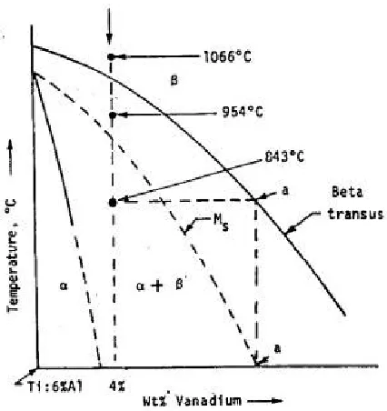
thermal treatment. The microstructural changes due to thermal treatment of the Ti-6Al-4V
alloy are most easily understood by observing the pseudo-binary Ti-6Al phase diagram
shown in Figure 2.1.
The microstructure produced due to thermal treatments varies depending upon the
temperature at which cooling begins and the cooling method used. The most common
methods of cooling, in order of quench rate, are water quenching, air cooling, and furnace
cooling.
Heating a Ti-6Al-4V specimen to 1066°C, which is above the transus, and keeping it there
for an hour produces a completely -phase microstructure. Water quenching a specimen
from 1066°C produces a microstructure consisting of all ’ (titanium martensite). The
microstructure of ’ martensite is characterized by individual platelets which are heavily
twinned and contain a HCP crystal structure. The grain refinement associated with the BCC
to HCP transformation and the increased dislocation density due to the rapid transformation,
strengthen the titanium martensite. Aging or tempering titanium martensite at certain
temperatures causes precipitation of the phase from the unstable ’ martensite, which
strengthens the alloy even further. Air cooling from 1066°C produces a microstructure made
up of acicular that is transformed from the phase by means of nucleation and growth.
Furnace cooling from 1066°C creates a microstructure that consists of coarse, plate-like
formed by nucleation and growth. Some phase is retained intergranularly due to the slow
cooling rate (2).
Heating a Ti-6Al-4V specimen to 954°C, which is below the transus, produces a
microstructure of primary coexisting with the phase. Water quenching the specimen to
microstructure of primary embedded in ’. Air cooling the specimen from 954°C produces
a microstructure consisting of primary in a transformed matrix, some of which is acicular
. Furnace cooling the specimen from 954°C produces a microstructure of equiaxed and
intergranular unchanged (2).
Heating a Ti-6Al-4V specimen to 843°C, just below the Ms temperature, produces a
microstructure with a lot less phase present than at the higher temperatures discussed
previously. Water quenching the specimen from 843°C produces a microstructure consisting
of primary and unchanged . The unchanged is metastable, and may undergo an ensuing
strain-induced transformation (2).
Forging a Ti-6Al-4V specimen also affects the resulting microstructure. A Ti-6Al-4V bar
forged with a 75% reduction in area at 982°C, just below the transus, and reheated 2 hours
at 732°C followed by air cooling, produces a microstructure consisting of platelike as well as
equiaxed with small amounts of transformed . Forging a similar bar with the same
amount of area reduction, but at a lower temperature of 899°C produces a microstructure
having fine elongated - . These results show that the microstructure becomes more
elongated the lower the temperature of working below the transus. If extensive hot
working is done below the transus, but above the recrystallization temperature, an equiaxed
2.2 Mechanical Properties
The tensile properties of Ti-6Al-4V alloys vary depending upon how it is processed. An
annealed Ti-6Al-4V bar typically has an ultimate tensile strength (UTS) of 130 ksi and a
yield strength (YS) of 120 ksi. It normally has a 10% elongation and a 20% reduction in
area. A solution treated aged bar and forgings 1 to 2 in thick give an UTS of around 150 ksi,
a YS of 140 ksi, 8% elongation, and 20% reduction in area. The hardness of Ti-6Al-4V
ranges from 36 to 39 HRC. Ti-6Al-4V has a Poisson’s ratio of 0.33 and an elastic modulus
of 110 GPa in tension and 117 GPa in compression. At room temperature (25°C), an
annealed plate of Ti-6Al-4V has a fracture toughness of about 68 ksi in1/2, and a fracture
toughness of 39 ksi in1/2 for a solution treated and aged sample (3).
2.3 Fabrication
The manufacturing of Ti-6Al-4V ingots into parts involves two steps: primary and secondary
fabrication. Primary fabrication consists of all processes that convert ingots into general mill
products such as billets, bars, plates, sheets, strips, extrusions, tubes and wires. Secondary
fabrication deals with manufacturing processes that produce finished parts from mill
products. These processes include die forging, extrusion, hot and cold forming, machining,
joining, and chemical milling; each of which can strongly influence the properties of
Ti-6Al-4V alloys. Since the Arcam EBM process only differs from regular forging and casting
Forging is a process in which metal is heated and shaped by plastic deformation using
compressive force, usually in the form of a hammer or press. Die forging can be categorized
into three groups: open-die forging, impression-die forging, and closed-die forging.
Open-die forging permits free deformation of at least some of the workpiece surfaces.
Impression-die forging yields much more constrained deformation, and closed-Impression-die forging gives
completely constrained deformation. Open-die forgings produce workpieces of lesser
accuracy than impression or closed-die forgings (4). With die forging, a variety of shapes can
be produced using relatively simple dies; however the process often requires a complex
sequence of deformation steps. Impression and closed-die forging produces parts using
complex die shapes, but require only a simplified sequence of deformation steps.
In the extrusion process, a workpiece is pushed against a deforming die while being
supported against unrestrained deformation in a container. This process allows for the
possibility of heavy deformations together with a wide array of extruded cross sections.
There are two different types of extrusion: direct and indirect. In direct extrusion, the
product emerges from the same direction as the movement of the punch meaning the
workpiece experiences friction with container wall. In indirect extrusion, the product travels
in the opposite direction of the punch. In this process, the workpiece is at rest and no friction
occurs (4).
Machining differs from forging and extrusion in that instead of plastically deforming a part,
be used to improve the tolerances and surface finishes of previously made workpieces. One
advantage of machining is that complex shapes, tolerances, and surface finishes can be
created that are often unattainable by other processing techniques. The disadvantage to
machining is that it removes material in the form of relatively small particles that are difficult
to recycle and can become easily mixed. This material is usually wasted as scrap (4).
The joining process differs from the previously discussed processes in that it takes parts
produced by other processes and combines them into a more intricate part. Permanent
joining processes are divided into four categories: mechanical, solid-state, fusion, and
liquid-solid. Mechanical joining uses mechanical fasteners such as rivets, stitches, staples, and
seams to join two or more workpieces. Solid-state welding involves the formation of
interatomic bonds by bringing the atoms of two surfaces close together. It consists of cold
welding, diffusion pressure, hot welding, and friction welding. Fusion welding is when the
imteratomic bond is made by melting the base metals and filler (if necessary). Liquid-solid
state bonding occurs when a filler metal is used to establish the joint. This process requires
no melting of the base metal and the strength of the bond is derived from the adhesion
between the filler and base metal. In liquid-solid state bonding (such as brazing and
soldering) the strength of the joint is higher than the strength of the filler (4).
Chemical milling is a process that is used to remove pockets of material. An etchant is used
dissolving certain parts of the material. This process is often used to create undercuts of a
material to increase the stiffness of panels with capped ribs.
2.4 Fracture Mechanics
The understanding of how a material fractures gives key insight into the properties of the
material. Every material can be categorized as ductile or brittle, or portraying qualities of
both. Ultimately, the atomic bonding of the material is the determining factor in whether or
not it is ductile or brittle. An ideally ductile failure is when the material necks down under
tension in a continuously plastic manner until the narrowing neck becomes atomically sharp
and the material splits apart. An ideally brittle fracture occurs when the material experiences
a sudden and catastrophic fracture with no observable plastic flow either prior to or during
failure(5). Ductile fracture is caused by dislocations of the atomic bonds, while brittle fracture
is caused by the creation of atomically sharp cleavage cracks. These cracks in a material can
concentrate the applied stress to the area of the crack tip resulting in a magnified stress many
orders of magnitude higher. Once this magnified stress at the crack tip surpasses the
maximum atomic bond strength, the crack will propagate through the solid and fracture the
material. Crack formation in materials occurs in a variety of ways by any mechanism that
locally causes an adequately high stress. The condition of a materials free surface affects
how easily a crack can form. A smooth surface will take longer to initiate a crack than a
machined surface. For a smooth surface, crack initiation almost always starts at the free
surface(6). In the cases where crack initiation occurs in the interior, an internal free surface
form ahead of the main crack and are connected by shear bands. The shear bands also
contain voids, but are normally much smaller than the holes they connect. The range of
resolved shear stress leads to slip band formation that cracks within the grains whose
orientation puts the preferred shear planes along the maximum shear directions (45° to the
applied stress). These slip bands migrate to the free surfaces of the material and cause
fracture. The ability of a crack to emit dislocations depends on its atomic structure, and the
type of bonding at the crack determines whether external chemicals can interact with the
crack in an embrittling fashion.
A crack consists of two steps, an initial cut made in the material, creating the cleavage plane,
and forces exerted on the free surfaces of the material which specify the particular fracture
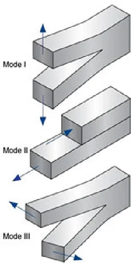
Figure 2.2: The three basic modes of fracture(7).
Mode I shows a tensile stress with the principle stress axis normal to the cleavage plane.
This mode is the only mode that leads to a physical fracture because it is the only mode
whose external stress physically separates the two surfaces on the cleavage plane; without
this separation, rewelding would take place even after the stress is applied. Mode II shows a
stress that is a shear parallel to the cut in the plane direction, while mode III shows a stress
that is a shear parallel to the cut in the antiplane direction(5). It is important to note that most
actual cracks are not pure cases. The crack fronts are not normally straight and the fracture
surfaces are not usually flat; thus it is possible that a crack may be produced which is mainly
2.5 Analysis Techniques
Several techniques were used in the evaluation of Ti-6Al-4V specimens produced by the
Arcam EBM S12. To evaluate the strength and ductility of the specimens, a 220-kip MTS
closed-loop universal testing machine was used to tensile test the samples. Fractography and
microscopy analysis were conducted using a JEOL 6400F Field Emission SEM, a Zeiss
Stemi 2000-C optical microscope, and a Zeiss Axiovert 40 MAT optical microscope. For the
machining of the samples final dimensions, a Cincinnati Milacron CNC milling machine was
used. Fracture toughness testing was conducted using a Fatigue Dynamics three-point bend
machine for the crack initiation, and a RSL four-point bend machine to break the samples.
References
1. R. Boyer. Metals Handbook Ninth Edition: Volume 9 Metallography and Microstructures. American Society for Metals. USA. 1985.
2. W. Smith. Structure and Properties of Engineering Alloys. McGraw-Hill, Inc. USA. 1993.
3. D. Betner et al. Metals Handbook Ninth Edition: Volume 3 Properties and Selection: Stainless Steels, Tool Materials and Special-Purpose Metals. American Society for Metals. USA. 1980.
4. J. Schey. Introduction to Manufacturing Processes. McGraw-Hill, Inc. USA. 2000.
5. R. Thomson et al. Fundamentals of Fracture: IV Cracking and Failure Mechanisms.
6. R. Sanford. Principles of Fracture Mechanics. Pearson Education, Inc. USA. 2003.
7. www.ndt-ed.org.
Chapter 3: Research
3.1 Sample Fabrication
Ti-6Al-4V samples were created from CAD models corresponding to the geometry given in
the ASTM E8 tensile coupon specification, as shown in Figure 3.1.
Figure 3.1: ASTM E8 Tensile Specimen Geometry
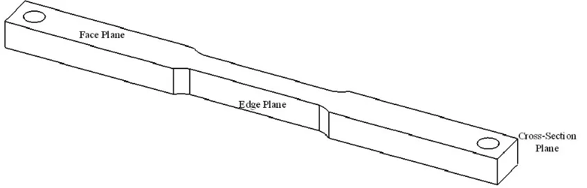
The three distinct surfaces on the tensile coupons were labeled as follows: face plane, edge
plane, and cross-section plane, as shown in Figure 3.2.
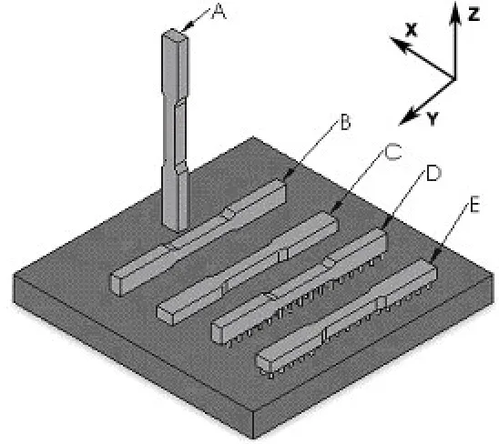
In order to evaluate the effect of sample orientation on the mechanical properties, samples
were built in three different orientations: standing up, laying down flat, and lying on the side.
Figure 3.3 shows the build orientations of the samples with respect to the start plate.
Figure 3.3: The build orientations of the Arcam EBM fabricated Ti-6Al-4V samples with respect to the start plate
Samples built in the orientation shown in specimen A were labeled “XZ,” while samples
built in the orientations B and C were labeled “YZ” and “XY,” respectively. Each of these
three build orientations has a unique solid-liquid growth interface oriented in the “Z”
Edge Plane Cross Section Plane Face Plane
Figure 3.4: The three, distinct solid-liquid growth planes; each growth plane is shaded for the three build orientations.
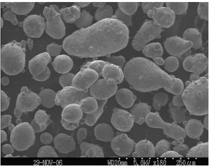
3.2 Powder Fabrication
All the samples fabricated in this research came from gas atomized Ti-6Al-4V powder
(except the fracture toughness samples, see Section 3.4.3). Gas atomization is a process that
involves liquid metal being separated into fine droplets that freeze rapidly before they come
in contact with each other or a solid surface. These fine droplets are created by high energy
jets of gas that impact the thin stream of liquid metal causing it to disintegrate. The resultant
powder is spherical/globular in shape without any internal porosity(1). Figure 3.5 shows the
Figure 3.5: Ti-6Al-4V gas atomized powder.
3.3 Microstructure
The Ti-6Al-4V specimens made using the Arcam EBM process were polished and etched for
microstructural analysis. The grinding and polishing sequence was as follows: 60, 120, 240,
320, 400, 600, 800, and 1200 grit, followed by 1.0 micron and 0.3 micron alumina. There
were several etchants used to bring out the various aspects of the microstructure. Kroll’s
reagent (3mL HF, 5mL HNO3, and 100mL H2O) was found to work well as an overall
etchant since it brought out the matrix and grain boundaries in the microstructure. Keller’s
reagent (2mL HF, 3mL HCl, 5mL HNO3, and 190mL H2O) also worked well as an overall
etchant when followed with a post etchant consisting of 1 mL HF, 2mL HNO3, 50mL H2O2,
and 47mL H2O. An etchant consisting of 10mL HF, 5mL HNO3, and 85mL H2O proved to
work well at bringing out the grain boundaries, while an etchant consisting of 6g NaOH,
16mL H2O, and 10mL H2O2 was found to work well at showing the matrix of the
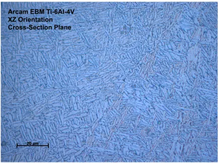
Micrographs taken of the Ti-6Al-4V specimens clearly show both the (HCP) and (BCC)
phases present in the microstructure. The (HCP) phase appears white and the (BCC)
appears black in the microstructure shown in Figure 3.6.
Figure 3.6: Optical micrograph of an Arcam EBM fabricated Ti-6Al-4V alloy showing the two phase (HCP)/ (BCC) microstructure.
As displayed in Figure 3.6, the (HCP) phase has an acicular or plate-like morphology. This
type of (HCP) morphology is common among many / titanium alloys, especially those
that have been cooled from the region(2)and as discussed previously in Chapter 2.1. The
(BCC) phase in Figure 3.6 appears to be located primarily in between the phase entities,
The (BCC) phase is shown much clearer when using a scanning electron microscope
(SEM). Figure 3.7 is a SEM micrograph that shows the (BCC) phase with better
resolution.
Figure 3.7: A SEM micrograph showing the morphology and distribution of the (BCC) phase in a EBM fabricated Ti-6Al-4V alloy.
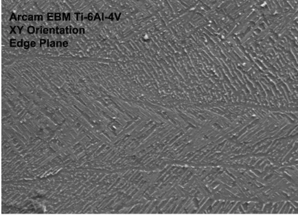
One microstructural characteristic that was prevalent in all three build orientation samples
was the presence of columnar boundaries. These columns were aligned normal to the planar
solid-liquid growth interface. The columns contained the two phase / mixture with the
(HCP) phase appearing to have preferred orientations within the columnar structures. Due to
this change in the (HCP) orientation between the columnar structures, along with the fact
fabricated metals under certain conditions , it is reasonable to assume that the columnar
boundaries found in these specimens represent grain boundaries. An example of the
columnar structure found in these specimens is shown in Figure 3.8.
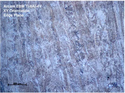
Figure 3.8: Optical micrograph of an Arcam EBM fabricated Ti-6Al-4V alloy showing the columnar grains normal to the planar solid-liquid growth interface.
In the figure above, the micrograph is of the edge plane of a XY build orientation sample.
The planar solid-liquid growth interface for XY oriented samples is the face plane; therefore
the columnar grains shown in Figure 3.8 are aligned perpendicular to this plane. The
cross-section plane of a XY oriented sample is shown in Figure 3.9. As expected, this figure shows
Figure 3.9: XY oriented sample showing columnar grains aligned perpendicular to the planar solid-liquid growth interface.
Since the face plane is the planar solid-liquid growth plane of the XY build oriented samples,
the microstructure should show the cross-section of the columnar grains. Figure 3.10 proves
Figure 3.10: Face plane of XY build oriented sample showing the cross-section of the columnar grains.
As previously mentioned, the presence of the columnar grain boundaries aligned
perpendicular to the planar solid-liquid growth plane is observed in all three build
orientations. This means that the face plane and cross-section plane for the YZ build
orientation should exhibit columnar grains, as well as the face plane and edge plane for the
XZ build orientation. These columnar grains are shown in Figure 3.11 a and b, and Figure
(A)
(B)
(A)
(B)
As it was with the XY build orientation, the cross-sections of the columnar grains for the YZ
and XZ build orientations were also present on the planar solid-liquid growth planes, as
shown in Figure 3.13 a and b.
(A)
(B)
As seen in the above figures, the diameters of the columnar grains’ cross-sections range from
about 100 to 200 m. The lengths of the columnar grains tend to run the entire span of the
specimens.
3.4 Mechanical Testing
The mechanical properties of the Arcam EBM fabricated Ti-6Al-4V alloys from each of the
three build orientations were established. Tensile testing was performed to determine the
UTS, YS, fracture strength (FS), and percent elongation of the specimens. Hardness was also
determined.
3.4.1 Tensile Testing
Tensile testing was conducted according to the parameters listed in the AMS 4999
specification and the results are listed in Table 3.1. Specimens labeled with a “P” indicate
that specimen was grown on pins instead of the heated steel start plate. Figure 3.14 compares
the average values of some of the mechanical properties for each of the three build
Table 3.1: Tensile Mechanical Properties of Ti-6Al-4V Specimens Fabricated Using the Arcam EBM Process
Specimens
Cross-Sectional Area
(in^2) (ksi) UTS Strength (ksi) %Elongation 0.2% Yield
Fracture Strength
(ksi)
XY1 0.0607 150.74 134.442 9.19 149.22
XY2 0.0588 152.02 138.819 6.68 151.40
XY3 0.0643 152.39 145.905 6.85 149.73
XY6 0.0623 153.01 143.454 8.49 152.61
XY7 0.0598 154.18 143.051 7.45 152.42
XY8 0.0605 167.80 160.548 17.03 160.71
XYP1 0.0571 170.35 161.522 14.13 166.10
XYP2 0.0620 153.52 144.970 16.27 148.82
Average 0.0607 156.75 146.59 10.76 153.88 StDev 0.0022 7.71 9.65 4.34 6.21
XZ1 0.0620 158.61 152.11 7.56 158.51
XZ3 0.0630 160.94 155.89 8.23 160.65
XZ6 0.0605 157.02 152.91 12.32 152.81
XZ7 0.0627 150.72 135.72 4.86 149.73
XZ8 0.0617 157.59 153.40 15.73 150.85
XZ9 0.0610 156.15 146.38 3.60 143.01
XZ10 0.0617 156.79 151.09 10.19 155.29
Average 0.0618 156.83 149.64 8.93 152.98 StDev 0.0009 3.12 6.79 4.22 5.91
YZ1 0.0603 152.05 141.45 17.24 136.56
YZ2 0.0620 152.80 141.96 13.44 149.16
YZ3 0.0610 154.57 139.34 14.75 146.28
YZ6 0.0620 153.75 133.06 16.86 138.43
YZ7 0.0618 158.36 137.16 16.01 151.03
YZ8 0.0625 153.90 143.46 13.13 149.63
YZP2 0.0608 140.40 134.38 12.54 138.17
YZP3 0.0605 154.44 138.25 16.16 145.50
Comparison of Mechanical Properties for the Three Different Build Orientations 0 20 40 60 80 100 120 140 160 180
UTS (ksi) 0.2% Yield Strength (ksi)
%Elongation Fracture Strength (ksi)
XY Average XZ Average YZ Average
Figure 3.14: Comparison of Average Tensile Mechanical Properties for the Three Different Build Orientations
As shown in the above table, specimens built in the XZ orientation had the highest average
UTS and YS values, however the values for the XY specimens were very similar. Although,
the YZ specimens were the weakest of the build orientations, they did have the highest
percent elongation meaning they were the most ductile. The XZ specimens had the lowest
ductility of the samples. This low ductility is likely linked to the columnar grains that are
aligned parallel to the tensile axis for the XZ build orientation. This same relationship may
also be the cause of the XZ specimens’ higher strength.
The samples that grew on pins (build orientations D and E from Figure 3.3) were devised as a
way to test the effect of the difference in the coefficients of thermal expansion (CTE)
CTE could lead to added stresses in the part, however, Table 3.1 shows that the samples
grown on pins displayed properties that, on average, were the same as the samples grown on
the steel start plate.
In order to validate the Arcam EBM process as an acceptable alternative to conventional
fabrication methods, the mechanical properties of Ti-6Al-4V alloy samples fabricated using
the Arcam EBM process were compared to Ti-6Al-4V samples fabricated by other methods
such as various casting, forging, and laser deposition procedures. These procedures are all
outlined in different Aerospace Material Specifications (AMS). Table 3.2 shows the
comparison of the average mechanical property values of the Arcam specimens compared to
the minimum allowable values of those fabricated according to various AMS procedures.
Table 3.2: Comparison of the Average Values of Selected Mechanical Tensile Test Parameters from Arcam EBM Fabricated 4V Alloys to Various Aerospace Material Specifications for the
Ti-6Al-4V Alloys Produced Using Already Established Methods
1. AMS-T 9047: Titanium and Titanium Alloys, Bars (Rolled or Forged) and Reforging Stock, Aircraft Quality
2. AMS-T 81915: Titanium and Titanium-Alloy Castings, Investment 3. AMS 4999: Titanium Alloy Laser Deposited Products 6Al-4V Annealed
4. AMS 4985C: Titanium Alloy, Investment Castings 6Al-4V 130 UTS, 120 YS, 6% EL Hot Isostatically Pressed Anneal Optional or When Specified
Process UTS (ksi)
Yield Strength
(ksi) %Elongation
Fracture Strength
(ksi) XY Average Arcam
EBM 156.75 146.59 10.76 153.88
XZ Average Arcam
EBM 156.83 149.64 8.93 152.98
YZ Average Arcam
EBM 152.54 138.63 15.02 144.34
AMS-T 90471 Forged, Square,
<.5 in2 165.00 155.00 10.00
AMS-T 819152 Cast 125.00 115.00 8.00
AMS 49993: (x
direction) Energy Beam
Process 130.00 116.00 4.00
(y&z direction) Energy Beam
Process 122.00 108.00 4.00
AMS 4985C4:
(separately-cast) Cast 130.00 120.00 6.00
(integrally-cast, designated
areas) Cast 130.00 120.00 6.00
(integrally-cast, nondesignated
Arcam EBM Properties Compared to Various AMS Properties 0 20 40 60 80 100 120 140 160 180 X Y A ve ra ge X Z A ve ra ge Y Z A ve ra ge A M S -T -9 04 7 A M S -T 8 19 15 A M S 4 99 9: (x di re ct io n) (y & z di re ct io n) A M S 4 98 5C : (s ep ar at el y-(in te gr al ly -c as t, de si gn at ed (in te gr al ly -c as t, no nd es ig na te d UTS (ksi)
Yield Strength (ksi) %Elongation
Figure 3.15: Comparison of the Average Values of Selected Mechanical Tensile Test Parameters from Arcam EBM Fabricated 4V Alloys to Various Aerospace Material Specifications for the
Ti-6Al-4V Alloys Produced Using Already Established Methods
From Table 3.2 and Figure 3.15, it is found that the Arcam EBM process exceeds all the
minimum requirements given in the cast and laser deposition specifications. The YS and
UTS for the forged specification (AMS-T 9047), however, are higher than those found for
the Arcam EBM samples. With the exception of the XZ samples, the Arcam EBM samples
meet the percent elongation requirement for the forged specification. Based on the results of
this data, it appears that the alloy samples produced by the Arcam EBM process in this study
generally meet or exceed the required mechanical properties for alloys that are produced
3.4.2 Hardness
Another manner of validating Ti-6Al-4V specimens produced by the Arcam EBM process is
to compare their hardness values to that of Ti-6Al-4V alloys produced by previously
established methods. Table 3.3 shows the average hardness values of the Arcam EBM
produced samples, from all three build orientations on all three surface planes, compared to
the hardness of a typical Ti-6Al-4V alloy.
Table 3.3: Average Hardness Values for Arcam EBM Produced Ti-6Al-4V Specimens Compared to a Typical Ti-6Al-4V Alloy
1: Source-Titanium Information Group
As shown in this table, the average hardness values for Arcam EBM produced Ti-6Al-4V
samples are essentially the same as that of Ti-6Al-4V alloys produced by previously
established methods.
Hardness Test
Specimen Plane Average Hardness (Rockwell C) Standard Deviation
XY Face 39.0 1.31
XY Edge 37.0 0.60
XY Cross-Section 36.6 1.74
YZ Face 35.6 0.99
YZ Edge 36.3 1.20
YZ Cross-Section 37.1 0.77
XZ Face 35.5 0.00
XZ Edge 36.7 1.15
XZ Cross-Section 38.2 1.04
Typical Ti-6Al-4V
3.4.3 Fracture Toughness
In addition to tensile and hardness testing, Ti-6Al-4V Arcam EBM fabricated samples also
underwent fracture toughness testing. The fracture toughness tests were carried out
according to the ASTM E399-90 standard(4). The samples were tested using a horizontal
build orientation (XY) and a vertical build orientation (XZ). The results of the fracture
toughness tests are shown in Figure 3.16.
Figure 3.16: Fracture Toughness Values for Horizontally and Vertically Oriented Arcam EBM Fabricated Ti-6Al-4V Specimens
From the figure, it is found that the average determined fracture toughness value is
The typical fracture toughness values for traditionally fabricated Ti-6Al-4V alloys range
from the upper 30’s to lower 90’s ksi-in1/2(5). One possible explanation for the rather low
fracture toughness values for these samples is the fact that powder used was made using a
plasma rotating electrode process (PREP). This process generally produces a less desirable
powder morphology, which could affect the material properties (see Section 3.6.3). In order
to obtain a more accurate understanding for the fracture toughness values of Arcam EBM
produced Ti-6Al-4V specimens, more samples will need to be tested.
3.5 Fractography
The fracture surfaces of the Arcam EBM produced tensile specimens were observed using a
SEM in order to understand their fracture behavior and the correlation between the samples’
microstructures and its tensile mechanical properties. Overall, the fracture surfaces appeared
to have a moderately ductile nature, as indicated by the present of dimples and microvoids.
The observance of slight necking in the specimens along with areas of plastic deformation in
the stress-strain curves further validates this claim. Fracture bands were also observed along
the surfaces, and appeared to coincide with the columnar grains found in the microstructure.
(A)
(B)
(C)
Figure 3.17 (A) shows a fracture surface of a XY oriented specimen with the face plane
aligned along the top and bottom edges of the image. The fracture bands in this image run
normal to this face plane direction, which is the same direction the columnar grains run for
this build orientation. Figure 3.17 (B) shows a fracture surface of a YZ oriented specimen
with the face plane aligned along the top and bottom edges of the image, as was the case in
Figure 3.17 (A). The fracture bands in this image run parallel to this face plane direction,
which is the same direction the columnar grains run for this build orientation. Figure 3.17
(C) shows a fracture surface of a XZ oriented specimen with the face plane aligned along the
same direction as in the previous two images. This image does not appear to display any
fracture bands, which would correspond to the fact that the columnar grains for this build
orientation run along the tensile axis, so only the cross-sections of the columnar grains would
be shown.
The images above provide evidence to state that there is a direct correlation between the
fracture bands and the columnar grains in these Arcam EBM produced samples. Thus,
considering that the XZ oriented samples were stronger than the XY and YZ oriented
samples, the columnar grains must be a factor in providing strength to these specimens.
Since the columnar grains remained intact on the fracture surfaces, it is likely that the cracks
propagated intergranularly. Intergranular crack propagation is also supported by the fact that
3.6 Improvement of Microstructural and Mechanical Properties
Although the mechanical data discussed previously shows the Arcam EBM process as a
favorable alternative to laser deposition and casting techniques, it is still of interest to
improve the mechanical properties of specimens produced by the Arcam EBM process so
that they meet the specifications for forged Ti-6Al-4V alloys as mentioned in AMS-T 9047.
Improvement of the mechanical properties can be achieved by refining the microstructure of
the material and reducing contamination. Some of the proposed methods for improvement
are as follows: varying the raster pattern and other parameters of the electron beam, hot
isostatic pressing (HIP) and/or heat treating at various times and temperatures, and varying
the morphologies and sizes of the powder alloy.
3.6.1 Varying the Process Parameters of the Arcam EBM Machine
One of the simplest ways to try and improve upon the properties of Ti-6Al-4V specimens
produced using the Arcam EBM process is to alter the parameters of the electron beam.
Power, beam velocity, traverse velocity, and raster pattern are all parameters that are
controllable on the Arcam EBM machine. There is little information available on the effects
of process parameters on mechanical properties for the Arcam EBM process. However,
research has been conducted on the effect of process parameters for a similar process called
Laser Engineered Net Shaping (Lens). LENS is a laser deposition process in which, like the
Arcam EBM process, metal parts are fabricated layer by layer directly from CAD models. A
study was conducted in which the power and traverse velocity of the laser beam was altered
changing the power and velocity of the laser, the deposition energy was altered, which was
found to affect the strength and ductility properties of the alloy. H13 tool steel is susceptible
to the Hall-Petch effect, which states that microstructures with finer grain sizes result in
higher yield strengths. A low deposition energy, characterized by low power (200 W) or
high traverse velocity (9.31 mm/s), allowed the molten pool to quickly solidify leading to a
finer microstructure with smaller grains(3) and therefore high yield and ultimate tensile
strength values. A high deposition energy, characterized by high power (300 W) and/or slow
traverse velocity (5.92 mm/s), produced parts with a coarser microstructure with larger
grains(3) and high ductility; thus the highest strength and ductility values cannot be attained
simultaneously.
This same study also observed how laser beam power affected the molten pool size in the
alloy, which in turn affects the thermal gradient across the molten pool and into the bulk
material. It was found that the size of the molten pool increased with power up to 275 W.
Using a power above 275 W caused the pool temperature to increase, but did not
significantly change the size of the molten pool. Since the molten pool size remained
constant, the heat dispersed into the bulk resulting in a lower cooling rate after solidification.
Research has also been conducted examining the effect of electron beam velocity on the
densification of H13 tool steel fabricated using the Arcam EBM process(7). In this study,
electron beam velocities of 2,500 mm/sec, 2,000 mm/sec, 1,500 mm/sec, and 1,000 mm/sec
The results of this experiment indicated that complete densification occurred in the samples
using beam velocities of 1,500 mm/sec and slower. The higher beam velocity samples
appeared to be very loosely bonded and therefore not suitable for usable parts.
Another parameter that is controllable on the Arcam EBM machine is the raster pattern. The
raster, or hatch, pattern is the direction and spacing in which the electron beam moves during
part fabrication. Altering this pattern can change the temperature gradients, cooling rates,
and melt flow of the material; all of which can impact the microstructural and mechanical
properties of fabricated parts. All the samples used in this work were made with the electron
beam changing 90° in direction between each layer. This raster pattern is shown in Figure
3.18.
First Layer:
Second Layer:
First Layer:
Second Layer:
Figure 3.18: Raster pattern used in Arcam EBM process
The direction of the electron beam can be changed between layers, as shown above, or
between passes within the same layer, both of which can affect the microstructure. To
understand how varying the raster pattern affects the temperature gradients and, in turn, the
technique was done in a previous study investigating the thermal history during LENS
processing(6). In this study, in-situ temperature readings were taken for twenty deposition
layers during the fabrication of H13 tool steel. The study revealed peaks in the temperature
each time the laser passed over or near the thermocouple, from the initial layer to subsequent
layer depositions. During the first layer deposition the temperature peaked at 1500°C and
quickly cooled to about 150°C. Each subsequent pass reheated the previous layers so that
after five layers were deposited, the initial layer still reached temperatures up to 900°C.
After thirteen layers were deposited, the thermocouple nominally read 500°C. Due to the
complex thermal cycling associated with the LENS process, the material properties of the
samples are affected much in the same way as they would be from tempering or aging.
Conducting a similar study for the Arcam EBM process using various raster patterns would
give insight as to how changing the raster patterns affect the microstructure and material
properties of a part.
3.6.2 HIP and/or Heat Treating at Various Times and Temperatures
Hot isostatic pressing and/or heat treating Ti-6Al-4V alloys is a common way to alter the
microstructure and mechanical properties of parts produced by traditional fabrication
techniques. Titanium alloys can be heat treated in order to: reduce residual stresses produced
during fabrication (stress relieving); produce the most favorable combination of ductility,
machinability, and structural and dimensional stability (annealing); increase strength
(solution treating and aging); and improve special properties such and fatigue strength,
Stress relieving Ti-6Al-4V alloys reduce the undesirable residual stresses resulting from:
nonuniform hot forging or deformation from cold forming and straightening, asymmetric
machining of forgings or plates, and welding and cooling of castings(8). Removing these
stresses helps maintain shape stability and prevents undesired conditions. Stress relieving of
Ti-6Al-4V alloys is done at temperatures between 480-650°C for 1 to 4 hours as stated in
AMS-H-81200A(9). After stress relieving, the alloys can be cooled by either air or furnace
cooling. Stress relieving parts fabricated using the Arcam EBM process may help relieve
residual stresses due to part formation and shaping.
Annealing Ti-6Al-4V alloys is mainly done in order to improve fracture toughness,
dimensional and thermal stability, and ductility at room temperature(8). Annealing titanium
alloys usually improves some properties at the expense of others, so the annealing cycle must
be selected in accordance with the desired property traits. There are several common types
of annealing treatments, but recrystallization annealing provides the optimal combination of
improvement in fracture toughness without significant loss in strength. This process is done
by heating the alloy into the upper range of the - region, held for a period of time, and then
slowly cooled. AMS-H-81200A recommends recrystallization annealing at temperatures
between 968-986°C, holding for 1 to 4 hours, air cooling or slower, reheating between
705-760°C for 1 to 2 hours and then air cooling again(9). Arcam EBM fabricated Ti-6Al-4V
alloys could undergo this process in order to improve their fracture toughness, while still
Solution treating and aging Ti-6Al-4V alloys can result in a wide range of strength values.
Heating a Ti-6Al-4V alloy to the solution treating temperature leads to a higher ratio of
phase, which can be maintained by quenching. Subsequent aging causes the unstable phase
to decompose, resulting in high strength. Solution treating is usually done high in the -
region in order to obtain high strength with sufficient ductility. The solution heat treating
schedule listed in AMS-H-81200A is heating between 900-970˚C for 20 to 120 minutes,
followed by water quenching(9). Water quenching provides the cooling rate necessary to
prevent the phase from decomposing and allows for the maximum response to aging.
Aging causes the supersaturated phase left over from quenching to decompose. The aging
schedule listed in AMS-H-81200A is heating between 480-690˚C for 2 to 8 hours, depending
on the desired strength level. Like the previous heat treatments, solution treating and aging
Ti-6Al-4V alloys fabricated using the Arcam EBM process can help provide the optimal
combination of strength, ductility, and toughness.
When heat treating Ti-6Al-4V alloys, it is important to consider the effects of contamination.
Heat treating must be done in a vacuum furnace or an inert atmosphere in order to prevent
oxidation of the alloy, which can produce a brittle surface layer. Heat treating in a vacuum
furnace or inert atmosphere also, more importantly, prevents having a high concentration of
hydrogen (above 125 to 200 ppm), which can lead to premature failure of a Ti-6Al-4V part(8).
HIP Ti-6Al-4V parts is also a relatively common way to increase some of the material
results in the removal of internal voids and helps create strong metallurgical bonds
throughout the material(10). The HIP part becomes almost 100% dense and homogeneous
with a uniformly fine grain size. Since HIP parts have reduced porosity, their mechanical
properties, such as fatigue strength, and workability are improved. AMS 4992 suggests that
Ti-6Al-4V parts be HIP in an inert atmosphere of 14.5 ksi or greater within the temperature
ranges of 899 to 954°C, held for 2 to 4 hours, and cooled under inert atmosphere to below
427°C(11). Subjecting Arcam EBM produced Ti-6Al-4V parts to this treatment could aid in
reducing some of the observed porosity in the parts and therefore, improving the mechanical
properties.
3.6.3 Varying the Morphologies and Sizes of the Powder Alloy
One of the most important aspects of the Arcam EBM process is how well the powder packs
in the Arcam chamber. Packing density is crucial in allowing adequate electrical and thermal
conductivity throughout the powder. Inadequate conductivity can cause the powder to
develop a buildup of negative charge, which causes the powder to repel against the electron
beam, thereby ruining the run. The powder density also plays a role in how well the powder
melts and flows during a run. Powder density is a result of the size and morphologies of the
powder itself. As mentioned in Chapter 3.2, all the Ti-6Al-4V powder used in this research
was gas atomized and ranged from 44 to 149 m in size. One obvious way to improve the
packing density of the powder would be to use powder that varies in size. This would allow
the powder could also increase its packing density. Thin, elongated “flake-shaped” powder
has the potential to pack more densely than powder of a spherical shape.
Currently, another method of powder production being used in conjunction with the Arcam
EBM process is plasma rotating electrode process (PREP). This process involves creating
the desired alloy in the form of a rotating bar that is arced with plasma gas. The bar is heated
by the plasma and the molten metal is centrifugally flung off of the bar, cooled down, and
collected as powder(12). The shape of the powder collected, however, is spherical and ranges
from 100 to 300 m in size, thereby making it less desirable than gas atomized powder due to
References
1. R.M. German. Powder Metallurgy Science: Second Edition. Metal Powder Industries Federation. Princeton, NJ. 1994
2. R. Boyer. Metals Handbook Ninth Edition: Volume 9 Metallography and Microstructures. American Society for Metals. USA. 1985.
3. P. A. Kobryn et al. Microstructure and Texture Evolution During Solidification Processing of Ti-6Al-4V. Journal of Materials Processing Technology. 2003.
4. ASTM E399-90. Standard Test Method for Plane-Strain Fracture Toughness of Metallic Materials. 1997.
5. www.matweb.com
6. M. L. Griffith et al. Understanding the Microstructure and Properties of
Components Fabricated by Laser Engineered Net Shaping (LENS). Sandia National Laboratories. Albuquerque, NM.
7. D. Cormier et al. Optimization of Electron Beam Melting Process. IIE Annual Conference. 09C Rapid Prototyping III. 2004.
8. D. Betner et al. Metals Handbook Ninth Edition: Volume 3 Properties and Selection: Stainless Steels, Tool Materials and Special-Purpose Metals. American Society for Metals. USA. 1980.
9. AMS-H-81200A. Heat Treatment of Titanium and Titanium Alloys. April 2001.
10. S. Mussman et al. Materials World. Volume 7. Number 11. Pages 677-678. November 1999.
11. AMS 4992. Castings, Structural Investment, Titanium Alloy 6Al-4V Hot Isostatically Pressed. October 2002.
Chapter 4: Conclusion
With the increasing market for rapid manufactured metal alloy parts, new fabrication
technologies must be established that are able to meet this demand. The Arcam EBM
process allows for the rapid manufacturing of metal alloy parts with low tooling costs and
essentially no material wasted as scrap. Parts having intricate dimensions and geometries are
able to be produced with little or no need for machining. With its unique capabilities, the
Arcam EBM process has potential applications in various markets, such as replacing parts on
military aircraft, complex engine designs, and medical implants. In order to establish this
technology as a viable alternative to traditional metal alloy manufacturing techniques, certain
material properties and characterization on parts produced using the Arcam EBM process
must be examined. The purpose of this research was to analyze the mechanical and
microstructural properties of Ti-6Al-4V alloys produced using the Arcam EBM process in an
effort to determine whether or not this process is an acceptable alternative to traditional
manufacturing methods.
Mechanical testing was conducted on Arcam EBM produced Ti-6Al-4V samples in
accordance with various AMS and ASTM standards and specifications. Microscopy was
also carried out in order to evaluate the microstructure of the samples. The relationship
between the mechanical properties and the microstructural properties of the samples was
established. The data collected from these samples was compared to the properties of
Ti-6Al-4V alloys fabricated using laser deposition, casting, and forging techniques. It was
minimum material property requirement given in these more traditional fabrication
processes, and is therefore, an acceptable fabrication process for Ti-6Al-4V alloys.
Suggestions on ways to improve the properties of Arcam EBM produced Ti-6Al-4V alloys
by altering the Arcam EBM parameters and using post fabrication heat treatment were given
in hopes to further establish this technology. Future work will consist in trying to produce
parts made from aluminum alloys in an effort to establish the Arcam EBM process as an
acceptable means of aluminum alloy fabrication as well.