Next Generation Muon
g
−
2
Experiments
David W. Hertzog1,a
1Department of Physics, University of Washington, Seattle, WA, 98195, USA
Abstract.I report on the progress of two new muon anomalous magnetic moment experiments, which are in advanced design and construction phases. The goal of Fermilab E989 is to reduce the experimental uncertainty ofaμ from Brookhaven E821 by a factor of 4; that is,δaμ ∼ 16×10−11, a relative uncertainty of 140 ppb.
The method follows the same magic-momentum storage ring concept used at BNL, and pioneered previously at CERN, but muon beam preparation, storage ring internal hardware, field measuring equipment, and detector and electronics systems are all new or upgraded significantly. In contrast, J-PARC E34 will employ a novel approach based on injection of an ultra-cold, low-energy, muon beam injected into a small, but highly uniform magnet. Only a small magnetic focusing field is needed to maintain storage, which distinguishes it from CERN, BNL and Fermilab. E34 aims to roughly match the previous BNL precision in their Phase 1 installation.
1 Introduction
At this Workshop, more than 25 presentations were de-voted to topics centered on the muon anomalous magnetic moment, aμ ≡ (g −2)/2. These included a discussion of the two new measurement campaigns – as reported in this paper – and the theoretical issues related to both the Standard Model prediction and various new-physics spec-ulations. In the narrative below, I will focus mainly on the Fermilab E989 experiment, which is in a mature construc-tion state. An important update since this Workshop has been the successful commissioning of the superconduct-ing storage rsuperconduct-ing magnet to its design field value and start of field-shimming operations. I will also briefly summa-rize the unique approach to measuringaμbeing taken by J-PARC E34 and point out, where it is important, the key differences between the experiments, [1].
1.1 Theg−2test
Muong−2 is a special quantity because it can be both measured and predicted to sub-ppm precision, enabling the so-calledg−2 test for new physics defined byaNew
μ ≡
aExpμ −aSMμ . As a flavor- and CP-conserving, chirality-flipping, and loop-induced quantity,aμis especially sensi-tive to new physics contributions [2, 3]. The currentg−2 test gives:
ΔaNewμ =[(263−289)±80]×10−11 (3.3−3.6)σ.
The range here represents different, but standard, evalua-tions [4, 5] of hadronic vacuum polarization (HVP) loops, and a common averaged value for hadronic light-by-light (HLbL) scattering. In fact, the range is even wider if all
ae-mail: [email protected]
efforts to evaluate the SM are considered. These topics re-ceived extensive scrutiny at this Workshop. If this range for ΔaNew
μ is confirmed at a greater significance, the pos-itive sign and relatively large magnitude – several times greater than the electroweak contribution – will provide important clues to the physics it is trying to reveal. The key phrase above is, “at a greater significance.” Let’s first focus on the combined experimental and theoretical uncer-tainty of 80×10−11and investigate what contributes to this value and how the combined error might be reduced in the future.
1.2 The Standard Model Inputs
The SM terms are usually listed in five categories:
aSM
μ =aQEDμ +aWeakμ +aHVPμ +aHad−HOμ +aHLbLμ
with a quadrature summed total uncertainty of ∼ 50× 10−11.
The QED and Weak term uncertainties are totally neg-ligible. These are impressive calculations. At this Work-shop, Melnikov provided an interesting discussion explor-ing in particular the QED calculations and whether they could be wrong in any way; he strongly argues “no” [6].
The HVP contribution [7] is determined from exper-iment through a dispersion relation that amounts to an energy-weighted integral of e+e− → hadrontotal cross sections. The uncertainty at 42×10−11 is non-negligible and presently dominates the overallδaμ(SM). This contri-bution depends on the accuracy of the reported data. Its quoted uncertainty is arrived at from reported cross sec-tion errors and, when necessary, errors are expanded to account for independent data sets that differ beyond statis-tical expectations. A small theorestatis-tical uncertainty owing
to radiative corrections is also important. New experimen-tal campaigns at BESIII [8] and the upgraded VEPP-2000 facility [9] in Novosibirsk, along with continued analyses of the large and varied BaBar data set [10] can be counted on to reduce the HVP uncertainty.
Higher-order HVP diagrams contribute a value of
−98.4×10⁻¹¹toaμ(SM), with negligible uncertainty. On the other hand, the higher-order HLbL effect is more prob-lematic. Curiously, it has a total contribution of approxi-mately+105×10−11, essentially canceling the HVP-HO term. At present, it can only be estimated using hadronic models, which typically have various strengths, weak-nesses, and different limitations. Assigning an uncertainty is almost a guess. We use 26×10−11, which is a consensus value reached by comparing models, but one could as well chose a number 50% larger, which many people do. More troubling is that these models could be badly wrong.
Fortunately intense efforts using lattice QCD have been making rapid progress toward a prediction of HLbL with an uncertainty goal below 10%. Lehner described re-cent efforts by the RBC and UKQCD Collaborations that aim to give 10% - 20% uncertainty soon on the quark-connected diagrams [11, 12]. Work in progress is focussed on the more difficult disconnected diagram, but the mes-sage given is that the end goal is achievable; it will be a matter of statistics more so than method.
An additional HLbL thrust is aimed at developing a data-driven approach using dispersion relations for the photon-photon scattering amplitude. Promising efforts de-scribed here by Procura [13] will make use of experimental spectra from BES III and KLOE that are now being har-vested.
1.3 The Experimental Inputs
The measurement of aμ is based on the following prin-ciples. When a muon with chargeq is circulating in the horizontal plane of a magnetic storage ring, its cyclotron frequency is ωc = −qB/mγ. The muon spin precesses at frequencyωs=−(gqB/2m)−[(1−γ)qB/γm], owing to the torque on the magnetic moment and including the Thomas precession effect for the rotating reference frame [14]. The magnitude ofωsis greater thanωcforg2. The diff er-ence is the anomalous precession frequency defined by
ωa≡ωs−ωc=−
g −2 2
qB m =−aμ
qB
m, (1)
where we have assumed for now a negligible effect from a non-zero electric dipole moment.
Parity violation inμ+ → e+νμν¯ eassociates the decay positron energies in the laboratory frame with the average spin direction of the muon at the time of the decay, such that the highest-energy positrons are preferentially emit-ted when the muon spin is aligned with its momentum and lower-energy positrons are emitted when the spin is reversed. Systems of detectors measure the decay positron times and energies.
To achieve the conditions described above, polarized muon bunches are injected into the magnet, kicked onto a
stable storage orbit, and are then observed non-intrusively until they decay. In practice, a > 95% polarized muon beam can be obtained by capturing forward decays of in-flight pions (π→ μν) in a beamline lattice made of alter-natively focussing then defocussing (FODO) quadrupole magnets. The captured beam will have a small, but finite, fractional transverse momentum component such that, un-aided, this beam could not be stored in a simple trans-verse magnetic field; the muons would escape if not for some kind of vertical containment field. At Fermilab, and earlier at BNL and CERN, this is provided by an electric quadrupole system, which creates a sort of Penning trap.
The motional magnetic field seen by a relativistic muon passing through an electric field E contributes an important term to the spin precession rate, represented by
ωa=− q m
⎡ ⎢⎢⎢⎢⎣aμB−
aμ−γ21
−1
β
×E c
⎤
⎥⎥⎥⎥⎦. (2)
At a muon momentum of pμ =3.094 GeV/c, (γ=29.4), the 2nd term in Eq. 2 exactly vanishes. The residual effect for muons slightly offthe magic momentum, and therefore not centered in the null region of the electric quadrupoles, results in anE-field correction to the measured precession frequency. The beam also executes horizontal and vertical betatron motions at frequencies determined by the weak-focussing index of the storage ring (i.e, the electric field strength). The vertical undulation of the muons meanspμ is not exactly perpendicular toB, thus a small “pitch” cor-rection is necessary. Combined, these corcor-rections shiftaμ by 86(6)×10−11 [15]; the error was negligible in E821, but will need to be reduced for E989. This will be ac-complished by more sophisticated particle tracking and by indirect measurements of the muon beam profile vs. time using an in-vacuum straw tracker system.
This detail is provided to contrast to the J-PARC ex-periment, which does not need such corrections. They will use a muon beam created by re-accelerating an ultra-cold, stopped muon source to a final injection momentum. The beam is predicted to have a relative transverse momentum of 10−5, a nearly negligible value.
In both experiments,aExpμ is obtained from two inde-pendent measurements – the anomalous precession fre-quency and the magnetic field – plus the evaluation of many systematic error categories. Detectors are used to measure the anomalous precession frequency ωa and pulsed proton NMR to measure the magnetic field in terms of the proton Larmor precession frequency, ωp. Both measurements involve frequencies that are measured us-ing highly stable precision oscillators. It is further nec-essary to know the muon distribution in the storage ring for the muon population that contributes to theωa data. This distribution is folded with similarly determined az-imuthally averaged magnetic field moments to give the ef-fective magnetic field seen by the muons, ˜ωpbelow. Given these experimentally determined quantities, one obtainsaμ at the precision needed through the relation
aExpμ = ge 2
ωa ˜ ωp
mμ
me μp μe
]
-11
10
×
Theory-Experiment [
-350 -300 -250 -200 -150 -100 -50 0 50
BNL E821
σ 3.6
Theory (2010)
FNAL E989
Future Goals
Theory
Figure 1. Comparison of Experiment to Theory at present and expected on completion of future Fermilab E989 and factor of
∼2 improvements in HVP and HLbL calculations.
In this expression, ag−2 experiment reports the ratio of the muon precession frequency to the proton precession fre-quency,R ≡ωa/ω˜p, where all systematic errors from the separate uncertainty table entries have been appropriately evaluated and combined in the uncertainty onR. That is the quantity reported by E821 [15]. From different exper-iments, one obtains the electrongefactor [16], the muon-to-electron mass ratio, and the proton-muon-to-electron magnetic moment ratio, [17]. Compared to the present 80×10−11 combined uncertainty in theg−2 test, these quantities are all known quite well. Of course, if any of their values change – e.g., the mass ratio was adjusted after the E821 final paper was published – one can updateaExpμ easily.
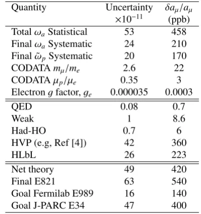
Table 1 summarizes the latest versions of the absolute and relative uncertainties of the theoretical and experimen-tal quantities used in theg−2 test. With the Fermilab E989 goal ofδaμ∼16×10−11, the quantities that stand out, sug-gesting targets for improvement, can be identified. On the experimental side, this will be achieved by a 21-fold in-crease in statistics and reductions of systematic errors by a factor of 2 to 3. On the theory side, continued improve-ment in the HVP evaluation – perhaps as much as a factor of 2 eventually? – might be expected. Furthermore, the promise of recent work on the lattice suggests that a re-duction of the HLbL uncertainty to∼ 13×10−11 is not an unreasonable goal. If the experiment and theory im-provements are met, the uncertainty on theg−2 test could reduce from 80 to 30×10−11 and the New Physics sig-nificance for the range quoted in Eq. 1.1 would approach 9σ. Figure 1 illustrates theg−2 test now and in this opti-mistic future, where the central values are not altered from present values.
2 The Experiments
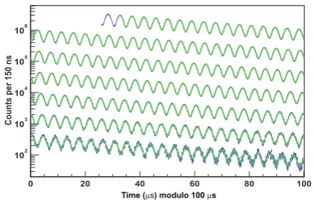
The classic data display for the anomalous precession fre-quency is shown in Fig. 2. It represents the arrival time distribution for positrons having energies above threshold
Eth. This simple method gives a statistical uncertainty on
Table 1.Uncertainties on the quantities used to determineaExpμ
andaSM
μ . Experimental errors from Ref [15]. Theory errors, see
Ref [6], except where noted. CODATA ratio uncertainties from the 2014 online update.
Quantity Uncertainty δaμ/aμ
×10−11 (ppb) TotalωaStatistical 53 458 FinalωaSystematic 24 210 Final ˜ωpSystematic 20 170 CODATAmμ/me 2.6 22 CODATAμp/μe 0.35 3 Electrongfactor,ge 0.000035 0.0003
QED 0.08 0.7
Weak 1 8.6
Had-HO 0.7 6
HVP (e.g, Ref [4]) 42 360
HLbL 26 223
Net theory 49 420
Final E821 63 540
Goal Fermilab E989 16 140 Goal J-PARC E34 47 400
Table 2.Comparison of various parameters for the Fermilab and J-PARCg−2 Experiments. Reproduced from [1].
Parameter Fermilab E989 J-PARC E24 Statistical goal 100 ppb 400 ppb Magnetic field 1.45 T 3.0 T
Radius 711 cm 33.3 cm
Cyclotron period 149.1 ns 7.4 ns Precession frequency,ωa 1.43 MHz 2.96 MHz Lifetime,γτμ 64.4μs 6.6μs Typical asymmetry,A 0.4 0.4 Beam polarization 0.97 0.50 Events in final fit 1.5×10¹¹ 8.1×10¹¹
the precession frequency of
δωa/ωa= 1 ωaγτμ
2
NA2P2. (4)
The uncertainty is improved by running at a higher field (ωa∝B), higher momentum (γτ), and high polarization of the incoming muon beam (P). The two experiments being mounted have rather different values for several of these parameters. In Table 2 – reproduced from [1] – the key differences are evident, including the precision goals. In both cases, the number of eventsNand the asymmetryA
depend onEth. Optimization of the “figure of merit”NA2 is achieved for Eth/Emax ≈ 0.6, which both experiments
assume.
2.1 Fermilab E989
2.1.1 Beamline
0 20 40 60 80 100
Counts per 150 ns
102 103 104 105 106
Time (μs) modulo 100μs
Figure 2. E821 anomalous precession data, including fit. The data is wrapped around every 100μs. Figure courtesy E821 col-laboration.
sequence is worth describing because it results in an ideal injected beam, having a pion contaminant fraction below 10−5, and no protons. These hadrons could have caused a large hadronic “flash” at injection, probably paralyzing the detector systems and leading to baseline shifts on a slowly decaying background, as was experienced in E821. The clean beam is considered to be a major improvement.
The sequence starts at the Booster, where short batches of 8 GeV protons are delivered to the Recycler Ring. An RF system separates a batch into 4 tighter bunches of
∼ 1012 protons each. These bunches are extracted one at a time and directed to the former antiproton target sta-tion, which is tuned to collect+3.1 GeV/cπ+. Pions are transported along a 270 m FODO lattice and then are in-jected into the repurposed ¯p Delivery Ring (DR), where they make several revolutions before being kicked into a final beamline that terminates at the storage ring entrance. Each bunch is separated by 11 ms or more, and 16 bunches are expected every 1.33-second accelerator cycle leading to an average storage ring fill rate of 12 Hz. The described beam path involves many changes compared to existing equipment. While the target system can be used nearly as is, the long beamlines and the DR needs significant work. A complete end-to-end simulation of the beam, from pro-duction to arrival at the storage ring was used to optimize the lattice and to predict the intensity and phase space dis-tribution of muons at injection. We expect up to 7×10⁵μ+
per bunch in a Δp/p ≈ 2% momentum bite – which is much greater than the ring acceptance of less than 0.2%.
2.1.2 Storage Ring
The BNL E821 storage ring [18] will be reused at Fermi-lab. Following a highly publicized move mostly on water from New York to Illinois of the superconducting coils, and a less-publicized move of hundreds of tons of steel yoke and other components by truck, the storage ring has now been fully re-assembled. It resides in the new MC-1 building, which has a strong supportive flooring system and a uniform and stable year-round temperature control.
During summer 2015, the magnet was first powered, followed by minor repairs to a superconducting lead. Full
power and full field were achieved in September. No muon would be stored in the magnet without a number of crit-ical storage ring subsystems, many of which are being upgraded significantly for E989. Muons first enter the ring through a bored-out tunnel through the back-leg iron yoke of the C-shaped magnet. They pass through the nar-row horizontal constrictions of a superconducting inflector magnet, which creates a nearly field-free corridor. Emerg-ing from the inflector, they traverse a high-gradient field region and cross through the outer electrode Al plate of one of the four electric quadrupole systems before entering the region of uniform magnetic field. One quarter of the way around the ring, a fast magnetic kicker applies an out-ward transverse 10-11 mrad angular kick during the first turn (only) placing the muon beam on the desired central orbit. Five collimators placed around the ring define the storage volume of 9 cm diameter transverse and circular storage volume.
This sequence is non-trivial to optimize. The incoming beamline Twiss parameters, the inflector angle and field magnitude, and the individual kicker magnitudes and fir-ing sequence can all be adjusted. Modern simulation tools were used to recreate the BNL E821 conditions and con-sequently led to design improvements for E989. For ex-ample, by reducing multiple scattering in the quadrupole plates and high-voltage standoff structures, a significant increase in the stored muon fraction can be obtained. Sim-ilarly, if the present close-ended windings on the BNL in-flector magnet were to be removed – a new design is in development with exactly this feature – the stored muon fraction will be nearly doubled.
One key device that demanded a major upgrade from the outset is the kicker magnet. For E821, its LCR-based pulse forming network was too slow and the magnitude of the kick too low. These led to an non-optimized storage fraction and large coherent betatron motions of the stored beam – a fact that resulted in a fairly large systematic un-certainty onωa. The new kicker will be energized through a Blumlein triaxial transmission line [19]. The pulse rises, flat-tops, and falls, within the 149 ns cyclotron period of the ring – an important fact. With newly shaped kicker plate geometry, the field magnitude can exceed the pre-dicted maximum, such that a tuning sweep can be per-formed to optimize the storage fraction while also mini-mizing the coherent betatron amplitude. The aim of these systems is to result in storage of about 18,000 muons per fill immediately after injection, an increase compared to BNL of about 2.5.
2.1.3 Precision Magnetic Field
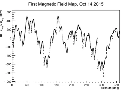
Azimuth [deg]
0 50 100 150 200 250 300 350
[ppm]
avg
) / B
avg
(B - B
-1000 -800 -600 -400 -200 0 200 400 600
First Magnetic Field Map, Oct 14 2015
Figure 3.First “as built” raw field map for the reassembled stor-age ring magnet for E989. The nominal field is 1.4513 T. The lumpy features will be greatly reduced as the shimming process begins (see text).
and the specifics of their dimensions determines the over-all field strength in the local region. The pieces are de-signed to be adjusted to account for the natural variance one starts with owing to tiny (10’s of microns) placement errors, and intrinsic magnetic material variances. The task began by establishing the baseline “raw field map”, as shown in Fig. 3. The data is obtained using a specialized shimming trolley having 25 NMR probes and Capacitec sensors that precisely measure the pole gap vs azimuth. The location of the shimming trolley is determined repro-ducibly by a laser alignment system. The field shown is obviously lumpy on the given scale, which is expected. The fine humped features stem from the curvature of each pole surface, which leads to a changing pole-to-pole gap and thus a strongly dependentBfield. The longer wave-length features are dominated by three things: the initial conditions of the wedge shims, the top-hat air gap, and the relative pole alignment. Adjustments to flatten these features rely on an iterative process that involves predic-tive actions based on anOPERA simulation, followed by re-measurement.
After coarse shimming is completed, the vacuum chamber system will be installed. It includes the inflector, electric quadrupoles, and the kicker. Further finer adjust-ments using active current shim coils will then be made. The field in the storage ring volume will be measured by thein vacuum trolley with 17 NMR probes, which rides on a set of rails inside the vacuum chamber and records its position using a bar-code reader. It is designed to enter the storage region and map the field exactly where the muons are stored.
All field measurements involve pulsed proton NMR, in which the upgraded data collection procedure will record the free-induction decay (FID) waveforms, rather than simply counting zero crossings. While the E821 sys-tem was indeed excellent, the many intervening years de-graded much of the inventory. After evaluating the status of the existing systems, a decision was made to build from scratch the 400 fixed probes and the 17 trolley probes. The
absolute field probe from E821 has been preserved and will be reused in E989. It was also the same probe used in the muonium hyperfine experiment that established the muon-to-proton magnetic moment ratio [20]. To comple-ment this key tool, new absolute probes are being devel-oped as further cross checks. The electronics to provide theπ/2 pulses and to record the FIDs is mostly new, as is much of the internal controller circuitry inside the trolley.
The uncertainty in the field measurement is entirely systematic. Many of the individual entries in the system-atic error table can be reduced naturally by additional, but not radical, efforts. The field systematic error in E821 was already at the 170 ppb level; for E989, the goal is 70 ppb. An underlying improvement that affects many of the sys-tematic issues is the intrinsic field variation in the stor-age volume – the goal of the intensive shimming program. Better location of the trolley during its measuring cycle, reduced trolley temperature fluctuations, greater field sta-bility from improved experimental hall temperature con-trol, a more complete set of fixed NMR probes, and storage of the FID waveforms which allows field determination in regions of higher gradients, are all important subplots to this unfolding story. As the work has just now begin, we can look forward in about a year to learn how successful the effort has been.
2.1.4 Detector Systems
The detector systems for E989 are entirely new, as is the supporting electronics, and the fast and slow data acquisi-tion systems. The detector systems will include:
• An entrance scintillating paddle and several sets of scin-tillating fiber hodoscopes to determine the incoming muon beam intensity profile vs. time and space.
• Two sets of rebuilt scintillating fiber hodoscopes placed in the path of the stored muons to measure (somewhat destructively) the stored beam x−y profile in two lo-cations; these detectors are used to optimize the storage and measure the coherent betatron motion. They are ro-tated out of the way for normal data taking.
• Three sets of in-vacuum straw trackers that reside in the scallop of the vacuum chamber adjacent to the muon storage volume. They provide data of decay positron tracks that can be “traced back” to the point of tangency from the muon that decayed. This provides a transverse stored-muon profile vs. time-in-fill. They also serve to calibrate the calorimeters and they are sensitive to an electric dipole moment of the muon (see [21]).
• Twenty-four stations of electromagnetic calorimeters that are positioned to maximally intercept the higher-energy decay positrons and determine their time of ar-rival and energy.
with rate – and must be reduced – a segmented and very fast calorimeter is being designed. Pileup occurs when two decay positrons strike the calorimeter at nearly the same time, and are interpreted as one decay with a larger en-ergy than either individually. If it exceeds Eth such that the event is accepted, the phase will be wrong because the two positrons that led to this fake single “high” en-ergy event had each traveled a shorter distance from their parent muons than the single high-energy positron would have that they mimic. That is, the time from muon decay to hit a detector is shorter on average for the low-energy positrons than the higher-energy positron. Mitigating the level of intrinsic pileup is accomplished by segmenting the calorimeter (unlike E821) and by choosing a technology that allows two-pulses to be resolved with a separation of just a few nsec.
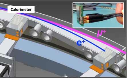
Each of the E989 calorimeters will consist of 54 PbF2
Cherenkov crystals stacked in a 6 high by 9 wide ar-ray. The compact placement, see Fig 4, and the proxim-ity to the storage ring field, does not allow conventional PMTs to be attached to the downstream face of the crys-tals. An ultra-fast readout based on the latest generation of Hamamatsu MPPCs (SiPMs, or silicon photomultipliers) will be used; see inset to Fig 4. Each SiPM has 57,600 50μm pitch pixels, all operated in Geiger mode. The summed current is routed to a bank of custom 800 MHz, 12-bit-depth, waveform digitizers. The SiPMs have ex-cellent gain stability if the temperature and bias are con-trolled; they are relatively impervious to rate (tested above 10 MHz); and, they are not affected by, nor do they affect, the magnetic field. Continuous digitization of the 54 crys-tals throughout each fill leads to a raw data rate of 18 GB/s for the 24 calorimeter stations, which is transferred to a bank of GPU processors where the sparsely occurring in-dividual pulse islands are extracted from the data stream and stored.
Paramount to the systematic control is a very high de-gree of gain calibration and gain stability, both long term and, even more importantly, short term. Over a 700μs fill, the instantaneous rate drops by more than four orders of magnitude, a typical recipe in detectors for a gain change. To monitor this precisely, a laser calibration system is be-ing developed [22] that will flash all crystals prior to each fill and, during special calibration runs, sparsely overlay calibration pulses on top of the real data in a pattern that leads to a series of 10−4 gain measurements every 5μs throughout the fill. The calorimeter system and gain sta-bility were tested at SLAC and the resolution and overall performance was excellent, see [23].
2.1.5 Reduction in Error Summary
The beamline and improved muon storage instrumentation will lead to the needed×21 in events to reach the desired statistical error of 100 ppb. The improved shimming, up-graded NMR system and analysis, and more frequent trol-ley maps, will reduce the ωp systematic uncertainty to a target goal of 70 ppb. The long and pure beamline will largely reduce the muon loss systematic. The improved
Calorimeter
Figure 4. Positioning of two of the segmented calorimeter sta-tions just downstream of the scalloped section of the vacuum chambers. The central muon orbit is sketched in, as is a nominal decay positron. The inset shows the size of the SiPM readout and its custom amplifier and pulse-shaping board.
kicker and adjustment of the weak-focussing tune, will re-duce the systematic error related to coherent betatron mo-tions. TheE-field and pitch corrections are improved by simulation and measurement. The pileup will be reduced by the segmentation and faster detector response, as well as the many times better resolution and much higher sam-pling and bit-depth of the digitizers. Finally, the gain sta-bility will be monitored by the new calibration system. Overall, the systematic error goal forωa is 70 ppb. The E989 total error budget is the quadrature sum of the above values, givingδaμ/aμ=140 ppb.
2.2 J-PARC E34
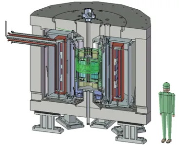
The J-PARC E34 Collaboration is developing a very uniqueg−2 experiment. They start with production of surface muons – those born from pions at rest – which have a momentum of 29 MeV/c. They are stopped in a silica aerogel target where micro-channels have been cre-ated using a laser ablation technique [24]. A large fraction of muonium M≡μ+e−atoms formed in the target diffuse out and emerge in a near field-free region in vacuum. The atoms at this point are essentially at rest. The triplet and singlet muonium combinations have relative populations of 12,14,0 and 14, for the (F,MF) states (1,1),(1,0),(1,−1) and (0,0), respectively.
Two lasers are fired on the M atoms. Aλ = 122 nm shot excites the 1S to 2P transition, and aλ=355 nm shot ionizes the atom, leaving a source of at-restμ+. The re-tained polarization isPz=50%, derived exclusively from atoms in the triplet (1,1) state. The (1,0) and (0,0) popula-tions can make transipopula-tions at the rateν24≈4.5 GHz, which
is so high that no net polarized signal will be left. To date, experiments at TRIUMF have demonstrated [24] a source scaled to J-PARC conditions of about 2×10⁵μ/s.
unique beam that could be used for a μ+−p scattering experiment such as the one proposed by MUSE to help re-solve the proton radius puzzle – but, that is another topic (see [1]).
The 10 times lower momentum muons compared to CERN, BNL and Fermilab, implies the need for a much
smaller magnet. Figure 5 shows the compact design,
which is based on a conventional MRI magnet, operated at 3 T. These magnets have rather uniform magnetic field throughout the inner volume. The muons are injected a steep vertical angle, then they are kicked to the horizon-tal plane, and finally a small additional magnetic field be-yond the solenoid is used to provide vertical containment
(it does not appreciably perturbωa). Because of the low
momentum and high field, the storage radius is just 33 cm and the cyclotron period is only 7.4 ns. The at-most polar-ization of 50% results in an asymmetry in the precession data of about half compared to Fermilab for the same rel-ative energy threshold. Further, the 10 times shorter life-time reduces considerably the measuring interval for each
fill, which affects the precision.
That said, there are many interesting features here. The magnet will not require nearly the attention to establish its mapped uniformity. The detector system uses a radial ar-rangement of vanes of silicon strip detectors that provide a uniform acceptance for in-curling positrons from any azimuthal decay position. The rates anticipated are very
high, but if the detector system can operate efficiently, it
should be relatively free of pileup and perhaps not subject to major gain changes. The EDM measurement, which both experiments will carry out in parallel, is well suited
here as it is based on up/down sloping tracks versus time.
The E989 experiment will have only a few tracker stations. The design of E34 is new enough such that even a working systematic error table has not yet been discussed
in public, so it is difficult to predict the final uncertainty
they can achieve. The Phase 1 statistical goal is roughly 400 ppb, a good comparison to BNL E821, but using a
very different method.
3 Summary
These are exciting times. As evidenced at this Workshop by the variety of presentations on specific calculations and
measurements, many people are working ong−2 in one
way or another. The motivation is clear for all. The current discrepancy between measurement and theory is one of the most promising indications of new physics, and the new experimental campaigns and the continued improvement in theory are leading to “discovery level” sensitivity in the
g−2 test. Fermilab E989 should begin collecting data
sometime in 2017. The collaboration will plan for a first result at roughly the precision level of BNL, but the ex-periment will run continuously to acquire the much larger data set, well into 2018 and possibly beyond. As with most modern precision experiments, the analysis is blinded and the emphasis on systematic uncertainty study completion will rule the timing of any result announcements. We are all looking forward to the next few years of vigorous ac-tivity.
Figure 5.The proposed setup for the J-PARCg−2 Experiment. Muons enter at the top left (green trajectory) and spiral into the highly uniform magnetic field region. Their decay positrons curl inward to an array of silicon tracking detectors. Figure courtesy T. Mibe.
Acknowledgments
The author thanks the organizers of this marvelous
Work-shop, his many colleagues on the Fermilab E989 g−2
experiment, and T. Mibe and G. Marshall from J-PARC
E34. The author is supported by the DOE Office of
Nu-clear Physics, award DE-FG02-97ER41020.
References
[1] T.P. Gorringe, D.W. Hertzog, Prog. Part. Nucl. Phys.
84, 73 (2015),1506.01465
[2] A. Czarnecki, W.J. Marciano, Phys.Rev. D64,
013014 (2001)
[3] D. Stockinger, this workshop, Recent developments
on the MSSM contribution to the muong−2.(2015) [4] M. Davier, A. Hoecker, B. Malaescu, Z. Zhang,
Eur.Phys.J.C71, 1515 (2011)
[5] K. Hagiwara, R. Liao, A.D. Martin, D. Nomura,
T. Teubner, J.Phys.G38, 085003 (2011)
[6] K. Melnikov, this workshop, Theory Review of muon
g−2.(2015)
[7] R. Chislett, this workshop, Leading-order hadronic
contribution to the electron and muong−2 (2015)
[8] M. Ablikim et al. (BESIII) (2015),1507.08188
[9] S. Eidelman, this workshop, Review on measurement
of the R ratio at Novosibirsk and ISR, and radiative corrections.(2015)
[10] Z. Zhang, this workshop, Review of recent
calcula-tions of the hadronic vacuum polarization contribu-tion to aμ.(2015)
[11] C. Lehner, this workshop, Hadronic light-by-light
contribution to(g−2)μfrom lattice QCD.(2015)
[12] T. Blum, N. Christ, M. Hayakawa, T. Izubuchi,
L. Jin, C. Lehner (2015),1510.07100
[13] M. Procura,et al,this workshop, Dispersion relation
[14] V. Bargmann, L. Michel, V. Telegdi, Phys.Rev.Lett. 2, 435 (1959)
[15] G. Bennett et al. (Muon G-2 Collaboration), Phys.Rev.D73, 072003 (2006)
[16] D. Hanneke, S. Fogwell, G. Gabrielse, Phys. Rev. Lett.100, 120801 (2008),0801.1134
[17] CODATA, CODATA 2014 Online Recommended Values.(2014)
[18] G. Danby, L. Addessi, Z. Armoza, J. Benante, H. Brown et al., Nucl.Instrum.Meth. A457, 151 (2001)
[19] J. Grange et al. (Muon g-2) (2015),1501.06858
[20] W. Liu, M.G. Boshier, S. Dhawan, O. van Dyck, P. Egan et al., Phys.Rev.Lett.82, 711 (1999)
[21] R. Chislett, this workshop, The EDM in the g−2
experiment(2015)
[22] A. Anastasi et al. (Muon g-2), Nucl. Instrum. Meth. A788, 43 (2015),1504.00132
[23] A. Fienberg, L. Alonzi, A. Anastasi, R. Bjorkquist, D. Cauz et al., Studies of an array of PbF2 Cherenkov crystals with large-area SiPM readout
(2015),1412.5525