IJEDR1502082
International Journal of Engineering Development and Research (www.ijedr.org)436
Protection of Low Voltage Ring Bus Type DC
Microgrid System with Probe Power Unit
1S.Saranya, 2S.Amirtharaj
1PG Student [Power System Engineering], 2Assistant professor Department of Electrical and Electronics Engineering
G.K.M College of Engineering And Tecnology, Chennai, Tamilnadu, India
Abstract — A multi-terminal DC power systems cannot survive or sustain high magnitude faults during fault conditions
and converters will shut down to protect themselves under faulted conditions. This makes locating faults in DC system difficult, and causes the DC bus to de-energize. A fault protection method for a low-voltage DC-bus microgrid system is presented. The main goal of the project is to detect and isolate faults in the DC-bus based microgrid system without interruption in the entire DC bus. A ring bus topology is utilized as the main DC bus and then bus is segmented into individual zones with solid state bi-directional switches used to isolate the zone in the event of a fault. Each zone is monitored and controlled by an individual segment controller. Also after fault clearance the circuit breaker recloses by comparing with the programmed threshold value. The DC ring bus is modelled with sources and load. A probe power unit is implemented to test the fault status. A fault creation, detection, isolation and reclosing operation concept is simulated and simulation result is verified using MATLAB/SIMULINK.
Index terms DC Power Systems, Microgrid, Power System Protection, Segment Controller, Solid-State Switch
I.INTRODUCTION
Many distributed power systems have been researched and developed, especially to meet the demand for high penetration of renewable energy resources, such as wind turbines and photovoltaic systems. The distributed power systems have advantages, such as the capacity relief of transmission and distribution, better operational and economical generation efficiency, improved reliability, eco-friendliness, and higher power quality. Compared to high-voltage dc (HVDC) transmission systems, the dc distribution system is a relatively new concept in electric power systems. DC microgrids have many advantages over traditional ac distribution systems. Furthermore, for a given cable, dc systems can deliver times more power than ac systems. This is because the usable power is based on the rms values in an ac system, while the dc power is based on constant current and voltage. DC systems do not suffer from skin effect, which allows the current to flow through the entire cable, and not just the outer edge.
Protection devices for ac systems are very mature and they are generally much cheaper than dc breakers since they are not specialty items. AC breakers rely on the natural zero crossings of the ac current; hence, these breakers cannot be applied in dc systems due to the lack of zero crossing in the dc current. Modification to existing circuit breakers (CBs) is possible, but this drives up cost and lead times. DC switchgear and CBs are expensive and may not always be available for certain systems. Also, the current power electronic devices cannot survive or sustain high magnitude faults. Converters will shut down to protect themselves under faulted conditions. This makes locating faults in DC system difficult, and causes the DC bus to de-energize. A fault protection algorithm and method for a low-voltage DC-bus microgrid system is presented in order to revolve the above issues. This paper proposes a dc bus microgrid fault protection method including backup protection that allows the fault to be detected and isolated without de-energizing the entire system.
II.MICROGRIDSYSTEM
The microgrid system is a small-scale distributed power system consists of distributed energy sources and loads, and it can be readily integrated with the renewable energy sources. Due to the distributed nature of microgrid approach, the connection to the central dispatch can be removed or minimized and in turn the power quality to sensitive loads can be enhanced.
Most microgrid systems have their connected distributed energy sources interfaced through power electronics converters. Generally they have two operation modes: standalone (islanded) and grid-connected operation. Microgrid systems can be divided into AC-bus and DC-bus systems, based on the bus that the component systems such as energy sources, loads and storages are connected. The challenge associated with protection of VSC-based microgrid systems is that the fault current must be detected and extinguished very quickly as the fault current withstand rating of typical VSCs is generally only twice the converter full-load rating. Semiconductor-based CBs have been investigated and they have been used for fast dc current interruption and over current limitation.
A. Possible Faults in LVDC
IJEDR1502082
International Journal of Engineering Development and Research (www.ijedr.org)437
cases it requires replacement of the device. A line-to-ground fault (ground fault) occurs when the positive or negative line is shorted to ground.In overhead lines faults may occur when lightning strikes the line. This may cause the line to break, fall to the ground and create fault. In this situation the fault is always permanent and the line must be isolated for repair. Ground faults may also occur by objects falling onto the line, such as trees, providing a path to ground. In some cases when an object causes the ground fault it may fall away from the line and the system can be restored. If the fault persists the line would have to be taken out of service until the fault path can be cleared.
III.PROPOSEDPROTECTIONSCHEME
The solid state circuit breaker and segment controller based protection method for the DC bus microgrid system is proposed. Unlike other methods, the proposed scheme does not require a interruption of service of the grid. Rather, only the affected section of the microgrid is isolated and de-energized. This is achieved through use of a ring bus configuration for the main DC bus, creating several zones of protection within the ring bus. This is done for both the positive and negative bus. T he ring bus will be split into zones and each zone is monitored by an segment controller as shown in Fig. 1. It will continuously monitor the current through it's assigned breakers. Once a fault is detected the controller will open the zone breakers. Ensuring that all of the breakers have opened and that the faulted zone is de-energized. If the zone has not been de-energized the zone controller will send signals to adjacent segment controller until the fault is extinguished. If the zone was successfully de-energized the segment controller will attempt to restore the faulted zone by reclosing the breakers. If a fault is then detected the zone breakers are again tripped and the zone is isolated. The proposed segment controller for one segment is shown below in Fig.2.
The novel protection method and algorithm for the DC bus microgrid system is proposed in this project. Unlike may other method the proposed scheme does not require a complete shutdown of the grid. Rather, only the affected section of the microgrid is isolated and de-energized. This is achieved through use of a ring bus configuration for the main DC bus, creating several zones of protection within the ring bus, and installing a grounding resistor to limit the fault current. This is done for both the positive and negative bus. The proposed protection scheme can be split into three sections:
Fault Detection Fault Isolation
Breaker Failure Detection Reclose and Restore
Fig.1 Block diagram of DC ring bus microgrid. Fig.2 Segment Controller
The ring bus will be split into zones and each zone is monitored by an segment controller. The segment controller will continually monitor the current through it's assigned breakers. Once a fault is detected the segment controller will open the zone breakers. The segment controller will then ensure that all of the breakers have opened and that the faulted zone is de-energized. If the zone has not been de-energized the zone segment controller will send signals to adjacent segment controller until the fault is extinguished. If the zone was successfully de-energized the segment controller will attempt to restore the faulted zone by reclosing the breakers. If a fault is then detected the zone breakers are again tripped and the zone is isolated.
A. Fault Detection and Isolation
The microgrid under study consists zones of protection. Each zone is classified by the type of energy device it has been assigned to. The zones can be split into 4 categories: uni-directional, bi-directional, load, and link. Each zone consists of 2-3 breakers and a section of cable. A local segment controller is assigned to each zone. The segment controller will monitor and control each of the breakers within its assigned zone. Each segment controller is programmed with the specific set of rules that define a normal zone operation. This is dependent on the source that the segment controller is monitoring. It should be noted that due to the ring bus configuration, current has several paths to flow.
IJEDR1502082
International Journal of Engineering Development and Research (www.ijedr.org)438
operate on the ring bus. Even with multiple faulted segments, the system can operate partially if the segments from the main source to some loads are intact. It has been assumed that the segment controllers can detect it and open/close Solid State Circuit Breakers in 500 µsec.B. Reclose And Restore
Once the faulted link was successfully separated and de-energized, the segment controller will attempt to reclose and restore. Faults are often temporary, caused by debris, animals, or other transients (e.g., lightning) contacting an energized line or bus. The temporary faults will clear themselves after current flows through the fault path. The reclose and restore mode allows the segment controller to autonomously restore power back to the de-energized zone. This is done by waiting a certain amount of time after the trip signals have been sent. After that, the segment controller will send close commands to all of the breakers. The waiting time depends on system configuration.
IV.DCRINGBUSFORMATION
DC ring formation is made by modelling the two or more renewable energy sources, AC and DC load, battery, main grid these are connected to the DC bus through respective converters may be uni directional or bi directional according to the need. DC bus is made to arranged as a loop type or ring bus formation. Here DC ring bus formation is modelled in which the solar energy system, wind energy system, AC machine, AC and DC load, battery backup, bi-directional converter and main grid all are connected to DC ring bus with circuit breakers in each segment of the DC bus. Also segment controller which controls the opening and closing of circuit breaker is implemented and operated through control system. Overall DC ring bus with all sources and load with protection is designed for analysis of fault detection and isolation.
A. Wind and Solar Energy System
The modelling of wind turbine and AC to DC converter is done using the Matlab 7.11 software. Here permanent magnet synchronous generator is used than induction generator because of its reduced size and high efficiency. It is shown in Fig.3. In wind turbine model the first input is the generator speed in per unit of the generator base speed for permanent magnet generator the base speed is the speed producing nominal voltage at no load. The second input is the blade pitch angle in degrees and the third input is the wind speed in m/s. The output is the torque applied to the generator shaft in per unit of the generator ratings. A wind turbine can only extract a part of the power from the wind which is limited by pitch angle controller and PMSG is made to work in generator mode by giving input as negative mechanical torque. As DC microgrid is used AC voltage has to be converted to DC thus AC to DC converter is coupled with the generator.
The model for solar energy system is simulated in matlab software shown in Fig.4. Solar energy system is considered as one of the sources in DC microgrid system it supplies DC voltage to the DC load and AC load which is connected to the ring bus. It is considered as the priority source of supply than wind energy system. If the pulse generator generates 0 switch will be in closed condition. If it generate 1 means the switch open and store the charge from solar in the capacitor. Also subsystem of solar energy system model consist of solar cells, current sensor and voltage sensor to sense current and voltage respectively, diode, MOSFET switch for production of DC current.
Fig.3. Wind energy system modelling Fig.4. Solar energy system model.
C. Segment Controller
A segment controller is placed in bus segment to control the opertation of circuit breakers. Once fault is detected then controller sends opening signal to open the respective circuit breaker which isolate the system. By the same it connects to the other sources to supply power to the load thus it handles fault detection, isolation and uninteruptted power to load.
V.PROTECTIONWITHPROBEPOWERUNIT
Once the faulted link was successfully separated and de-energized, the segment controller will attempt to reclose and restore. The temporary faults like transients or animals contacting an energized line will clear themselves after current flows through the fault path. This is done by waiting a certain amount of time after the trip signals have been sent.
So far, the bus CBs have been reclosed without knowing the status of the fault. If the fault has not been cleared, the same fault current would flow again and it could damage the system. A probe power unit is to test the fault status of the bus segment before reclosing the circuit breaker. The probe unit consist of a capacitor, inductor, power sources and connection switches. The power source applies a certain voltage that is just high enough to inject a probe current to see if the fault persists. The reclosing of circuit breaker can be conducted much safer because the main CB will be closed only when no-fault status is confirmed.
2 -1 +
Generator speed (pu)
Pitch angle (deg)
Wind speed (m/s) Tm (pu)
Wind Turbine model
v + -Scope wr1 Pitch_angle1 Pitch_angle-controller m A B C Tm PMSG m a k m a k m a k m a k 50 30 2 -1 + v + -s -+ Voltage Source v + -Vout Solar System
Series RLC Branch
IJEDR1502082
International Journal of Engineering Development and Research (www.ijedr.org)439
VI.V. SIMULATIONRESULT
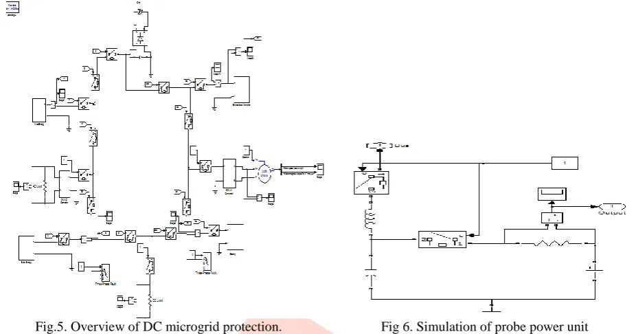
The proposed protection scheme was performed with computer simulations using MATLAB. The overview of entire DC microgrid protection is shown Fig 5 and A probe power unit is shown in Fig.6.
Fig.5. Overview of DC microgrid protection. Fig 6. Simulation of probe power unit
During normal operating conditions solar is chosen as main priority os sources to supply AC and DC load. The simulation result for solar supplying load before the fault occurrence is shown in Fig.7 and 8.
A line to ground fault is created at the solar link circuit breaker at 0.2sec after the fault occurrence the current magnitude raises immediately which is detected by segment controller. The breaker near the solar energy system opened and AC and DC load which is connected to solar system is supplied through the wind energy system. Thus solar energy system is isolated without any interruption in power supply to the load.
Fig.7. Simulation result for solar supplying 24V to DC load. Fig.8. Simulation result for AC load at 24V.
If the wind speed is low and unable to supply these load then the breakers opened and connected to the AC grid. Thus AC grid supplies required voltage to the loads. The breaker conditions under no fault and after fault occurrence is shown in Fig.9. BREAKER SIGNAL AFTER FAULT OCCURENCE
TIME(S)
1=
Clo
se
d/
0=
O
pe
n
FAULT OCCURRED AT 0.2S SOLAR
SOLAR LINK
WIND
WIND LINK
GRID
GRID LINK
DC LOAD
AFTER FAULT ISOLATION
Simulation result for AC load after fault isolation
V O L T A G E
TIME(S) FAULT OCCURRED AT 0.2S
Fig.9. Breaker signal after fault occurrence. Fig.10. Simulation result for AC load after fault isolation.
IJEDR1502082
International Journal of Engineering Development and Research (www.ijedr.org)440
C U R R E N T
TIME(S)
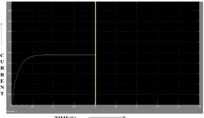
Fig.11. Simulation result for solar output current after fault isolation. Fig 12. Simulation result for probe power unit
VII.CONCLUSION
This paper has presented a fault detection and isolation scheme for the low-voltage dc-bus microgrid system. The proposed protection scheme consists of segment controllers capable of detecting abnormal fault current in the bus and separating the faulted segment to avoid the entire system shutdown. A loop-type dc-bus-based microgrid system with segment controllers between connected components has been proposed. The proposed protection concepts have been validated by computer simulations and experiments. A probe power unit is implemented to test the fault status. The proposed scheme can be applied to dc power systems, such as Green Buildings, with sustainable energy resources and data centers with a server array. Challenges, such as a reduction of conduction loss in the solid-state CBs and fault ride through capability, and fault-location techniques need to be investigated.
REFERENCES
[1] M. Saeedifard, M. Graovac, R. Dias, and R. Iravani, “DC power systems:Challenges and opportunities,” in Proc. IEEE Power and Energy Society Gen. Meeting, Jul. 2010, pp. 1–7.
[2] R. Cuzner and G. Venkataramanan, “The status of DC micro-grid protection,” in Proc. IEEE Ind. App. Soc. Annu. Meeting, Oct. 2008, pp.1–8.
[3] D. Salomonsson, L. Soder, and A. Sannino, “Protection of low-voltage DC microgrids,” IEEE Trans. Power Del., vol. 24, no. 3, pp.1045–1053, Jul. 2009.
[4] P. Salonen, P. Nuutinen, P. Peltoniemi, and J. Partanen, “LVDC distribution system protection: Solutions, implementation and measurements,” in Proc.13th Eur. Conf. Power Electron. App., 2009, pp. 1–10.
[5] J. Candelaria and J.-D. Park, “VSC-HVDC system protection: A review of current methods,” in Proc. IEEE/Power Energy Soc. Power Syst. Conf. Expo., Mar. 2011, pp. 1–7.
[6] C. Jin and R. Dougal, “Current limiting technique based protection strategy for an industrial DC distribution system,” in Proc. IEEE Int. Symp. Ind. Electron., Jul. 2006, vol. 2, pp. 820–825.