583 |
P a g e
EFFECT OF CORE AND FACE SHEET THICKNESS
ON DYNAMIC PARAMETER OF BEAMS USING FEM
AND ABAQUS
1
Md Shahbaz Alam,
2Md Tanwir Alam,
3Najeeb ur Rahman,
4Md Naushad Alam
1
M.Tech,
2Research Scholar,
3Assistant Professor,
4Professor
Department of Mechanical Engineering, Aligarh Muslim University, Aligarh (India)
ABSTRACT
In this paper, finite element analysis of isotropic and sandwich beams are presented by using ABAQUS software
keeping time constant. Various combinations have been chosen by varying beam thickness in case of isotropic
beam and core thickness and face sheet thickness in case of sandwich beam. The results are generated on
ABAQUS to compare the fundamental frequency of vibration for selected beams against the first order shear
deformation theory (FSDT) model. It is perceived from isotropic and sandwich beam results that an increase in
the face sheet thickness produces an increase in modal frequency. The material chosen for this purpose is
Aluminum 6061 T-6. Different modes of vibration frequency are alsodiscussed in the present scenario.
Keywords- ABAQUS,Beams, FEM
1. INTRODUCTION
In the competitive aerospace industry which is based on light weight and high strength structures, the usage of
composite sandwich materials are essential in meeting the severe performance requirements. Foam core
sandwich structures are utilized in a number of aerospace applications such as fabrication of wing flaps, aircraft
flooring, and interior secondary structures. The benefits of using a foam core are reduced parts count, seamless
construction, light weight, low cost and offers higher reliability of product quality [1]. Knowing these numerous
applications, vibration of sandwich structures is of extreme interest to engineers and designers in the aerospace
industry as these structures experience a wide range of dynamic loads during flight profile [2].The core material
is usually low strength material, but its higher thickness provides the sandwich composite with
high bendingstiffness with overall low density.The core is bonded to the skins with an adhesive or with metal
components by brazing together [2]. The advantages of sandwich material are high bending stiffness combined
with low mass, smooth surfaces, good fatigue behavior, good thermal insulation, good dampening capacity and
high energy absorption [3, 4].Application of sandwich materials in damped are structures for effective vibration
damping, aerospace field, building construction, naval ships, rail industry and automotive industry[2].
584 |
P a g e
Finite element method (FEM) is the dominant discretization technique in structural mechanics. The basic
concept in the physical interpretation of FEM is the subdivision of the mathematical model into disjoint
components of simple geometry called finite elements. The response of each element is expressed in terms of a
finite number of degrees of freedom characterized as the value of an unknown function, at a set of nodal points.
The response of the mathematical model is then considered to be approximated by that of the discrete model
obtained by connecting or assembling the collection of all elements. Finite elements do not overlap in space.A
typical finite element analysis on a software system requires the nodal point spatial locations, elements
connecting the nodal points, mass properties, boundary conditions, loading function details and analysis options.
Abaqus is a powerful engineering simulation software based on the FEM. The unique features of Abaqus
include an extensive library of elements that can model virtually any geometry. A complete Abaqus analysis
usually consists of three distinct stages pre-processing, simulation and post –processing. The Abaqus/CAE is the
complete Abaqus environment that provides a simple, consistent interface for creating Abaqus models,
interactively submitting and monitoring Abaqus jobs, and evaluating results from Abaqus simulations.
Abaqus/CAE is divided into modules, where each module defines a logical aspect of the modelling process
[5-6].
II MODELLING OF BEAMS
In the present work, the geometric parameters that define the isometric and sandwich beams are illustrated in
Fig.2 (a & b). Material properties of A6061-T6 [1] is tabulated in Table 1. Procedure of modeling of isotropic
beam is shown in the Fig. 1 while Fig. 2(a & b) shows the geometry of the isotropic beam and sandwich beam.
Modelling of sandwich beam is same as that of isotropic beam except partition of the beam. The sandwich is
partitioned in upper and lower face sheet by central core.
Table 1 Material Properties of Aluminum 6061-T6
Material Property Young’s Modulus Poisson’s Ratio Density
Aluminium 6061-T6 68.9GPa 0.33 2700kg/m3
585 |
P a g e
Figure2. Geometry of (a) Isotropic beam and (b) Sandwich beam
III RESULTS AND DISCUSSION
The result section demonstrates the validity of the analytical model by first verifying an aluminum isotropic
case.
This is followed by sandwich beam trends associated with varying face sheet thickness and core thickness. The
present analysis shows the effect of thickness variation of isotropic and sandwich beams consist of face sheets
and core of the same material (A6061-T6) on the fundamental frequency of vibration. The results are generated
on Abaqus and are compared against FSDT model [1].
3.1 Isotropic Beam Thickness Variation
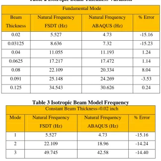
Comparison of the fundamental frequency of vibration for the isotropic beam model of varying beam thickness
[1] against the result fromFSDT model has shown in Table 2.Table 3 illustrates the five model frequency using
the Abaqus and evaluated alongside FSDT values. These results are calculated for a beam with constant
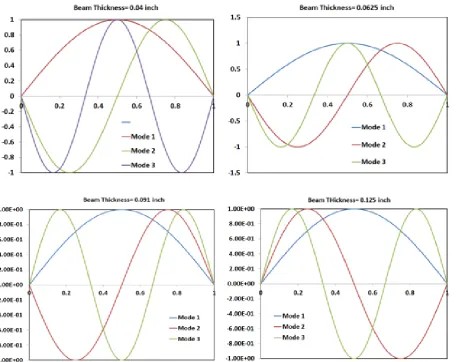
thickness of 0.02 inch. Fig.3shows the result of isotropic validation graphically. The first three mode variations
of isotropic beam of different thickness is shown in the Fig.4. Isotropic beam bending images of different modes
are shown in the Fig.5(a, b & c). It is seen that as the beam thickness increases the frequencies of FSDT and
ABAQUS model also increases as shown in the Table 2 & 3. The difference in frequencies are evaluated in the
form of % error (see Table 2 & 3). The FSDT and ABAQUS frequencies are validated with respect to the
variation of the beam thickness as shown in the Fig.3. It revealed from the results that all frequencies increases
with the thickness of the beam for all three modes. But the slope of the frequency of mode 3 is more as
586 |
P a g e
vibration in the beam for mode 3 will be large and hence the deflection will be higher as compared to the mode
1 and 2. This can be clearly seen in Fig. 4 and Fig. 5 for deflection.
Table 2 Isotropic Beam Thickness Variation
Fundamental Mode Beam Thickness Natural Frequency FSDT (Hz) Natural Frequency ABAQUS (Hz) % Error
0.02 5.527 4.73 -15.16
0.03125 8.636 7.32 -15.23
0.04 11.055 11.193 1.24
0.0625 17.217 17.472 1.14
0.08 22.109 20.334 8.04
0.091 25.148 24.269 -3.53
0.125 34.543 30.626 0.24
Table 3 Isotropic Beam Model Frequency
Constant Beam Thickness=0.02 inch
Mode Natural Frequency
FSDT (Hz)
Natural Frequency
ABAQUS (Hz)
% Error
1 5.527 4.73 -15.16
2 22.109 18.96 -14.24
3 49.745 42.58 -14.40
587 |
P a g e
588 |
P a g e
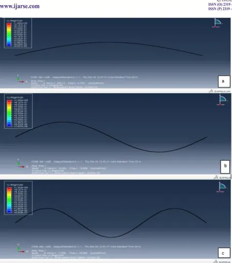
Figure 5. Images of isotropic beam of thickness 0.02 inch for (a) first mode, (b) second mode and
(c) third mode
3.2 Sandwich Beam Thickness Variation
3.2.1 Constant Core Thickness 0.25 inch
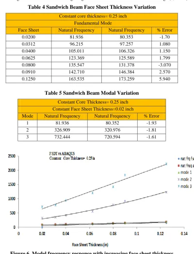
The first analysis is performed by varying face sheet thickness and keeping core thickness constant. This
analysis is performed using an aluminum 6061-T6 metal sandwich beam. This signifies that the core and the
face sheet are all manufactured from same material [1]. The results are presented in Table 4 and Fig 6. The
589 |
P a g e
demonstrate that frequencies increases very fast as compared and hence the deflection too as shown in the Fig.8.
Also, increment of frequency in case of sandwich beam is large as compared to the isotropic beam.The first
three mode variations of sandwich beam of different face sheet thickness and constant core thickness 0.25 inch
is shown in the Fig.7. Sandwich beam bending images of different modes are shown in the Fig.8(a, b & c).
Table 4 Sandwich Beam Face Sheet Thickness Variation
Constant core thickness= 0.25 inch Fundamental Mode
Face Sheet
Thickness (inch)
Natural Frequency
FSDT (Hz)
Natural Frequency
ABAQUS (Hz)
% Error
0.0200 81.936 80.353 -1.70
0.0312 96.215 97.257 1.080
0.0400 105.011 106.326 1.150
0.0625 123.369 125.589 1.799
0.0800 135.547 131.378 -3.070
0.0910 142.710 146.384 2.570
0.1250 163.535 173.259 5.940
Table 5 Sandwich Beam Modal Variation
Constant Core Thickness= 0.25 inch Constant Face Sheet Thickness=0.02 inch
Mode Natural Frequency
FSDT ( Hz)
Natural Frequency
ABAQUS (Hz)
% Error
1 81.936 80.352 -1.93
2 326.909 320.976 -1.81
3 732.444 720.594 -1.61
590 |
P a g e
591 |
P a g e
Figure8. Images of sandwich beam for (a) first mode, (b) second mode and (c) third mode
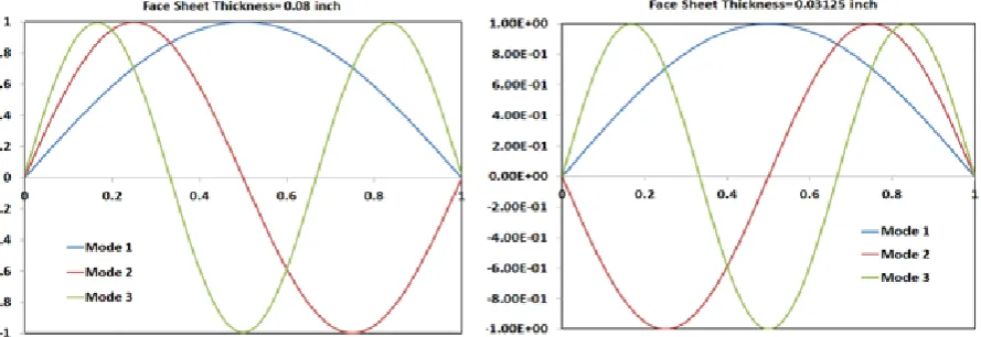
3.2.2Constant Face Sheet Thickness
Figure 9 shows the mode variation of sandwich beam for constant face sheet thickness 0.03125 inch. Images of
592 |
P a g e
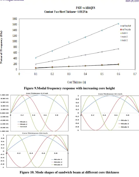
thickness of sandwich beam with the frequencies are shown in the Table 6 and predicted that frequency
increases with the core thickness. Although, for constant core and face sheet thickness, frequency variation is
dependent on mode variation and there is very high increment is depicted with higher mode (see Table 7 and
Fig.9). It is clearly evident from the results that % error decreases at higher mode as shown in the Table 7. The
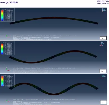
deflection in the sandwich beam for three modes are shown in the Fig.11. The higher frequency shows the large
deflection in the beam and vice-versa. Due to the high frequency in case of mode 3 as compared to the mode 1
and mode 2, the greater deflection are predicted.
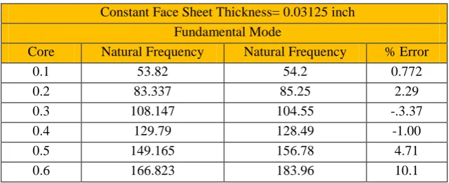
Table 6 Sandwich Beam Core Thickness Variation
Constant Face Sheet Thickness= 0.03125 inch
Fundamental Mode Core
Thickness
Natural Frequency
FSDT ( Hz)
Natural Frequency
ABAQUS (Hz)
% Error
0.1 53.82 54.2 0.772
0.2 83.337 85.25 2.29
0.3 108.147 104.55 -.3.37
0.4 129.79 128.49 -1.00
0.5 149.165 156.78 4.71
0.6 166.823 183.96 10.1
Table 7 Sandwich Beam Model Variation
Constant Core Thickness = 0.2 inch
Constant Face Sheet Thickness = 0.03125
Mode Natural Frequency
FSDT (Hz)
Natural Frequency
ABAQUS (Hz)
% Error
1 83.337 80.352 -3.88
2 332.687 288.800 -13.18
593 |
P a g e
Figure 9.Modal frequency response with increasing core height
594 |
P a g e
Figure 11. Images of sandwich beam for (a) first mode, (b) second mode and (c) third modeIV CONCLUSION
The analytical model matches exceptionally well with the results obtained from ABAQUS output for the
isotropic beam validation. Additionally, it is observed from isotropic and sandwich beam results that an increase
in the face sheet thickness produces an increase in modal frequency. Also, the effect of FSDT is not critical for
the fundamental mode of vibration. However, at higher modes ABAQUS greatly under predicts the natural
frequency response of the sandwich beam. Similar trends are observed if the face sheet thickness is kept
constant and the core thickness is increased. Additionally, an increase in core thickness can be construed as an
595 |
P a g e
REFERENCES
[1] S. Jamil, M. Steven, E. Habib andZ. Yi, Higher Order Dynamic Equations of Motion for Soft Core sandwich
beam using Hamilton’s principle, 52nd AIAA/ASME/ASCE/AHS/ASC Structures, Structural Dynamics and
Materials Conference<BR> 19th4 - 7 April 2011.
[2] M.R. Obbineni, Dynamic Stability Analysis of Sandwich Beam with Functionally Graded Material
Constraining Layer, NIT, Rourkela, May 2013.
[3] Liu, Qunli, and Z. Yi, "Effect of Soft Honeycomb Core on Flexural Vibration of Sandwich Panel using
Low Order and High Order Shear Deformation Models." Journal of sandwich Structures and Materials 9
(2007): 95-108.
[4] K. Stamm and H. Witte, Sandwich konstrukionen- Berechung, Fertigung, Ausfuhrung; Springer Verlag,
Wien 2013.
[5]G Kopp, J Kuppinger, HE Friedrich and F Henning,Sandwich-Strukturenfür
denfunktionsintegriertenLeichtbau- Lightweight Design, Springer, 2009.